

- Posts: 68
- Thank you received: 6
TCP 5-axis kinematics
5 years 1 month ago #221413
by jurod
Replied by jurod on topic TCP 5-axis kinematics
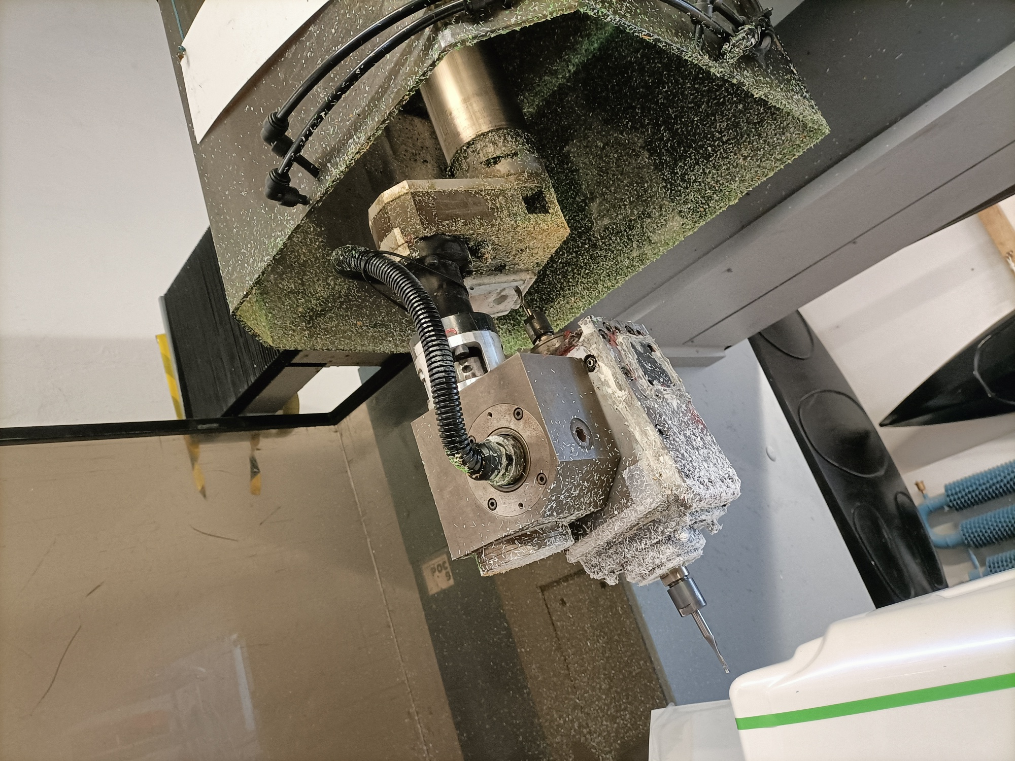
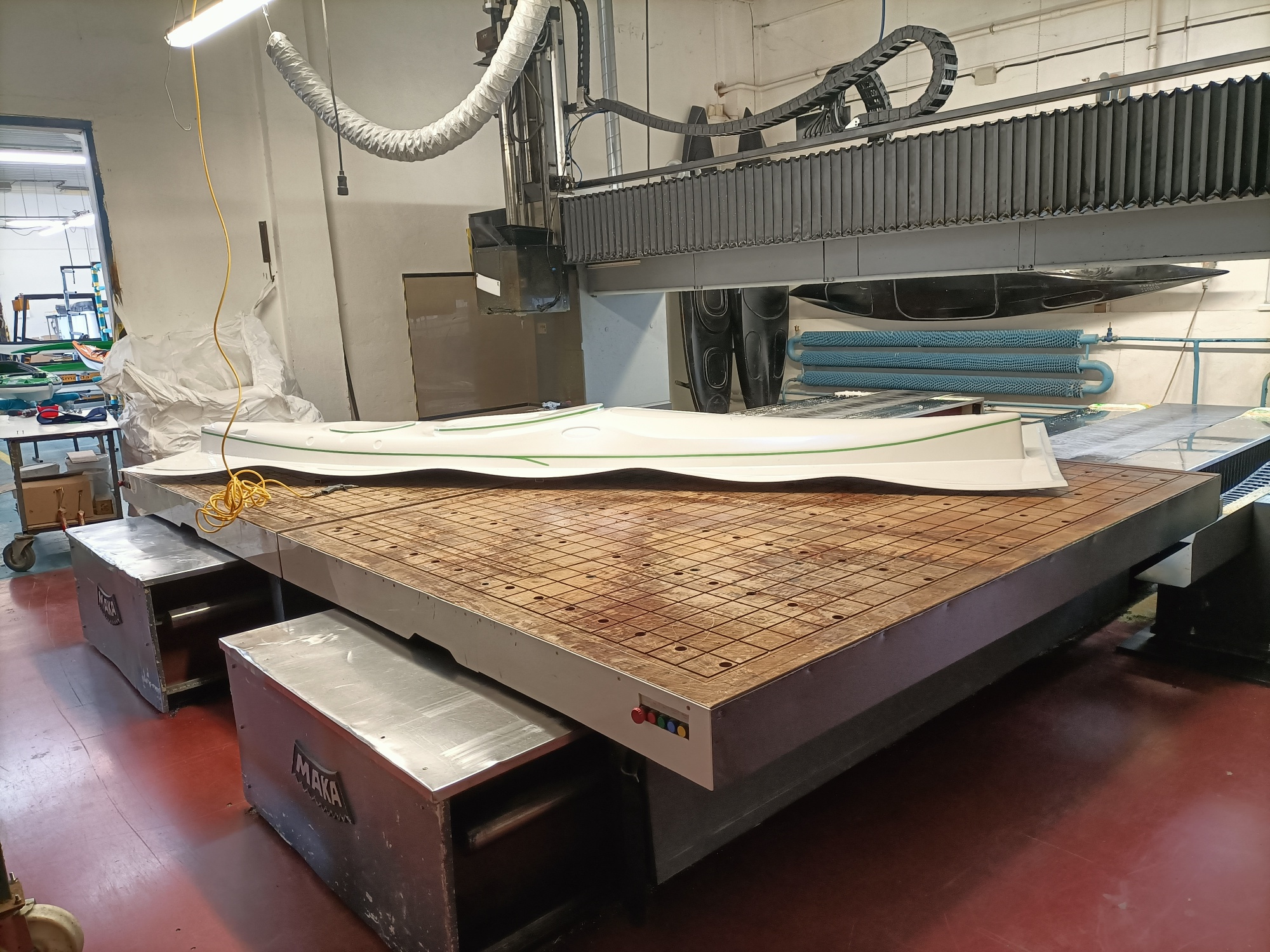
I am sending photo.
So should i go back to 2.8.2?
So should i go back to 2.8.2?
Please Log in or Create an account to join the conversation.

5 years 1 month ago #221438
by Aciera
Replied by Aciera on topic TCP 5-axis kinematics
Nice machine. Looks like the XYZBC-SRT kinematics would be the most likely to help you. The most important thing is to get the offsets of the rotational axis correct. Do you have any dimensional drawings of the machine head?
No, I think you would want to use the master version as you might find the 'switchable kinematics' feature useful.So should i go back to 2.8.2?
Please Log in or Create an account to join the conversation.
5 years 4 weeks ago #222108
by jurod
Replied by jurod on topic TCP 5-axis kinematics
Is the XYZBC-srt module to download somewhere?
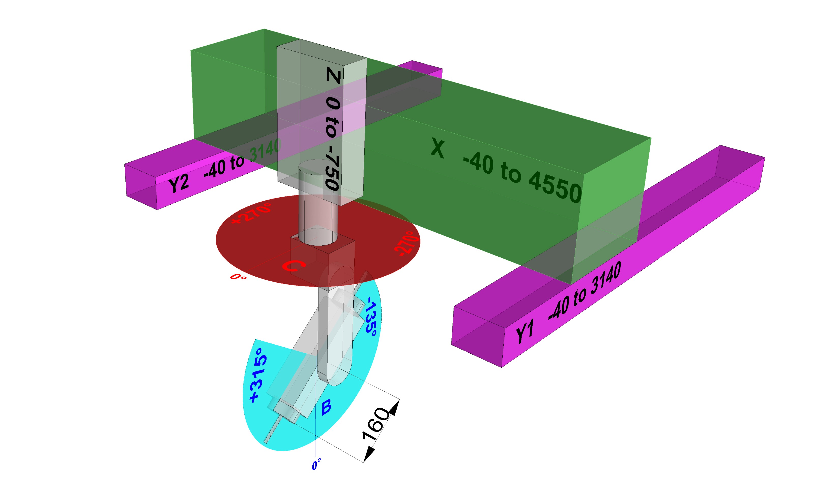
Dimensional drawing in the photo.
Dimensional drawing in the photo.
Please Log in or Create an account to join the conversation.
5 years 4 weeks ago - 5 years 4 weeks ago #222190
by Aciera
Replied by Aciera on topic TCP 5-axis kinematics
Have a look at 5axiskins.c in the linuxcnc/src/emc/kinematics folder. That kinematic is used in the simulation configuration found at /configs/sim/axis/vismach/5axis/bridgemill/5axis.ini
Inside '5axiskins.c' you will find some commentary and the definition of the DEFAULT_PIVOT_LENGTH that you will probably want to change to 160:
/********************************************************************
* Description: 5axiskins.c
* kinematics for XYZBC 5 axis bridge mill
*
* Derived from a work by Fred Proctor & Will Shackleford
*
* Author:
* License: GPL Version 2
* System: Linux
*
* Copyright (c) 2007 Chris Radek
*
* Notes:
* 1) pivot_length hal pin must agree with mechanical
* design (including vismach simulation) and augmented
* with current tool z offset
* (typ: mechanical_pivot_length + motion.tooloffset.z)
* 2) C axis: spherical coordinates aziumthal angle (t or theta)
* projection of radius to xy plane
* 3) B axis: spherical coordinates polar angle (p or phi)
* wrt z axis
* 4) W axis: tool motion. Negative values increase tool radial
* motion example: drilling into body at b,c angles
* 5) W axis motion is incorporated into the motion of the
* joints used for X,Y,Z positioning and no motor or
* hal pin connections are required for the joint specified
* as JW. However, a joint must be configured for W to
* support display of the W axis letter value for
* complicated reasons. (motion/control.c computes joint
* positions only for the number of configured kinematic
* joints (NO_OF_KINS_JOINTS) and the joint positions
* are needed to display axis letters via inverse
* kinematics.
* 6) If no coordinates module parameter is supplied, kins
* will use the required coordinates XYZBCW mapped
* to joints 0..5 in sequence.
* 7) Multiple joints may be assigned to an axis letter
* with the module coordinates parameter
* If a coordinates module parameter is supplied,
* the kins will map coordinate letters in sequence
* to joint numbers beginning with joint 0.
* 9) Coordinates XYZBCW are required, AUV may be used
* if specified with the coordinates parameter and will
* be mapped one-to-one with the assigned joint.
********************************************************************/
// non-required coordinates (A,U,V) can be set by using
// the module coordinates parameter
#define REQUIRED_COORDINATES "XYZBCW"
#define DEFAULT_PIVOT_LENGTH 250
Note that this kinematic creates a hal-pin called 'pivot_length':
struct haldata {
hal_float_t *pivot_length;
Make sure you provide the required value (ie your 160mm plus any tool-length offset) in your hal. As in the file '5axisgui.hal' in the 'bridgemill' simulation configuration. You will probably want to remove the stuff for the vismach script so you will end up with something like this:
# compute pivot-length needed for 5axiskins
loadrt sum2 names=pivotsum
addf pivotsum servo-thread
setp pivotsum.in0 160
net :tool-len <= motion.tooloffset.z
net :tool-len => pivotsum.in1
net :pivot-len <= pivotsum.out
net :pivot-len => 5axiskins.pivot-length
Inside '5axiskins.c' you will find some commentary and the definition of the DEFAULT_PIVOT_LENGTH that you will probably want to change to 160:
/********************************************************************
* Description: 5axiskins.c
* kinematics for XYZBC 5 axis bridge mill
*
* Derived from a work by Fred Proctor & Will Shackleford
*
* Author:
* License: GPL Version 2
* System: Linux
*
* Copyright (c) 2007 Chris Radek
*
* Notes:
* 1) pivot_length hal pin must agree with mechanical
* design (including vismach simulation) and augmented
* with current tool z offset
* (typ: mechanical_pivot_length + motion.tooloffset.z)
* 2) C axis: spherical coordinates aziumthal angle (t or theta)
* projection of radius to xy plane
* 3) B axis: spherical coordinates polar angle (p or phi)
* wrt z axis
* 4) W axis: tool motion. Negative values increase tool radial
* motion example: drilling into body at b,c angles
* 5) W axis motion is incorporated into the motion of the
* joints used for X,Y,Z positioning and no motor or
* hal pin connections are required for the joint specified
* as JW. However, a joint must be configured for W to
* support display of the W axis letter value for
* complicated reasons. (motion/control.c computes joint
* positions only for the number of configured kinematic
* joints (NO_OF_KINS_JOINTS) and the joint positions
* are needed to display axis letters via inverse
* kinematics.
* 6) If no coordinates module parameter is supplied, kins
* will use the required coordinates XYZBCW mapped
* to joints 0..5 in sequence.
* 7) Multiple joints may be assigned to an axis letter
* with the module coordinates parameter
*
If a coordinates module parameter is supplied,* the kins will map coordinate letters in sequence
* to joint numbers beginning with joint 0.
* 9) Coordinates XYZBCW are required, AUV may be used
* if specified with the coordinates parameter and will
* be mapped one-to-one with the assigned joint.
********************************************************************/
// non-required coordinates (A,U,V) can be set by using
// the module coordinates parameter
#define REQUIRED_COORDINATES "XYZBCW"
#define DEFAULT_PIVOT_LENGTH 250
Note that this kinematic creates a hal-pin called 'pivot_length':
struct haldata {
hal_float_t *pivot_length;
Make sure you provide the required value (ie your 160mm plus any tool-length offset) in your hal. As in the file '5axisgui.hal' in the 'bridgemill' simulation configuration. You will probably want to remove the stuff for the vismach script so you will end up with something like this:
# compute pivot-length needed for 5axiskins
loadrt sum2 names=pivotsum
addf pivotsum servo-thread
setp pivotsum.in0 160
net :tool-len <= motion.tooloffset.z
net :tool-len => pivotsum.in1
net :pivot-len <= pivotsum.out
net :pivot-len => 5axiskins.pivot-length
Last edit: 5 years 4 weeks ago by Aciera.
Please Log in or Create an account to join the conversation.

4 years 11 months ago - 4 years 11 months ago #225768
by annhan
hi all,
I am building the scara robot.
The switch kins is very good.
I want to move the scara in joint mode, but I want to use the position and Gcode in world mode.
When I run a gcode, it will calculate the position to know the angle of joins, after it move joins.
any idea helps me.
thank you so much
Replied by annhan on topic TCP 5-axis kinematics
hi all,
I am building the scara robot.
The switch kins is very good.
I want to move the scara in joint mode, but I want to use the position and Gcode in world mode.
When I run a gcode, it will calculate the position to know the angle of joins, after it move joins.
any idea helps me.
thank you so much
Last edit: 4 years 11 months ago by annhan.
Please Log in or Create an account to join the conversation.
4 years 11 months ago #225941
by Aciera
Replied by Aciera on topic TCP 5-axis kinematics
Not sure I understand the question.
Scarakins should take care of calculating cartesian position from joint angles (forward kinematic) as well as calculating the joint angles for a given cartesian position (inverse kinematic).
The switch kins feature will let you switch between 'joint' mode and cartesian 'world' mode.
Scarakins should take care of calculating cartesian position from joint angles (forward kinematic) as well as calculating the joint angles for a given cartesian position (inverse kinematic).
The switch kins feature will let you switch between 'joint' mode and cartesian 'world' mode.
Please Log in or Create an account to join the conversation.
Time to create page: 0.184 seconds