Linuxcnc and Profibus
- Aciera
-
 Topic Author
- Offline
- Administrator
-

Less
More
- Posts: 4734
- Thank you received: 2121
05 Oct 2021 13:43 #222282
by Aciera
Linuxcnc and Profibus was created by Aciera
This is a quick demonstration of a Festo CPV10-GE-DIO2-8 valve block connected through Profibus-DP interface using the PC-serial port. This uses the 'pyprofibus-master' found here:
github.com/mbuesch/pyprofibus
Note that since this is a python project it runs in userspace. So really only interesting for I/O extension modules. None the less it might be very useful for refitting larger machines:
Videolink: user-images.githubusercontent.com/460672...3b9-0c0c37a73e04.mp4
github.com/mbuesch/pyprofibus
Note that since this is a python project it runs in userspace. So really only interesting for I/O extension modules. None the less it might be very useful for refitting larger machines:
Videolink: user-images.githubusercontent.com/460672...3b9-0c0c37a73e04.mp4
The following user(s) said Thank You: RotarySMP, tommylight
Please Log in or Create an account to join the conversation.
- RotarySMP
-

- Offline
- Platinum Member
-

Less
More
- Posts: 1627
- Thank you received: 595
05 Oct 2021 18:11 - 05 Oct 2021 18:13 #222298
by RotarySMP
Replied by RotarySMP on topic Linuxcnc and Profibus
That is cool. Now I feel bad for buying the direct control module my CPV10. Did you connect this through one of those USB widgets which Andy posted?
forum.linuxcnc.org/26-turning/41498-scha...fit?start=200#220605
Looking through the GitHub, I would have no idea where to start to use this widget. Im not a complete idiot (I hope), but there is no clear thread in there which would give an indication to a low level user, which of the large number of files need to be downloaded, where they need to be installed, how to integrate them into LinuxCNC, or how to use it to control a profibus device.
The link to hardware is broken.
Maybe it was good this idiot got the Festo multipol control module")
Mark
forum.linuxcnc.org/26-turning/41498-scha...fit?start=200#220605
Looking through the GitHub, I would have no idea where to start to use this widget. Im not a complete idiot (I hope), but there is no clear thread in there which would give an indication to a low level user, which of the large number of files need to be downloaded, where they need to be installed, how to integrate them into LinuxCNC, or how to use it to control a profibus device.
The link to hardware is broken.
Maybe it was good this idiot got the Festo multipol control module
Mark
Attachments:
Last edit: 05 Oct 2021 18:13 by RotarySMP.
Please Log in or Create an account to join the conversation.
- Aciera
-
Topic Author
- Offline
- Administrator
-
Less
More
- Posts: 4734
- Thank you received: 2121
06 Oct 2021 06:21 - 06 Oct 2021 06:24 #222333
by Aciera
Replied by Aciera on topic Linuxcnc and Profibus
Well, it did take me a couple of days to figure it out, mostly because I really had no clue about Profibus.
The author doesn't recommend using a usb to RS485 adapter, because of the time lags that can happen with USB, although I did quickly try with one and it seemed so be working well enough. The recommended way is to use an RS232 port with a TTL to RS485 adapter like this:
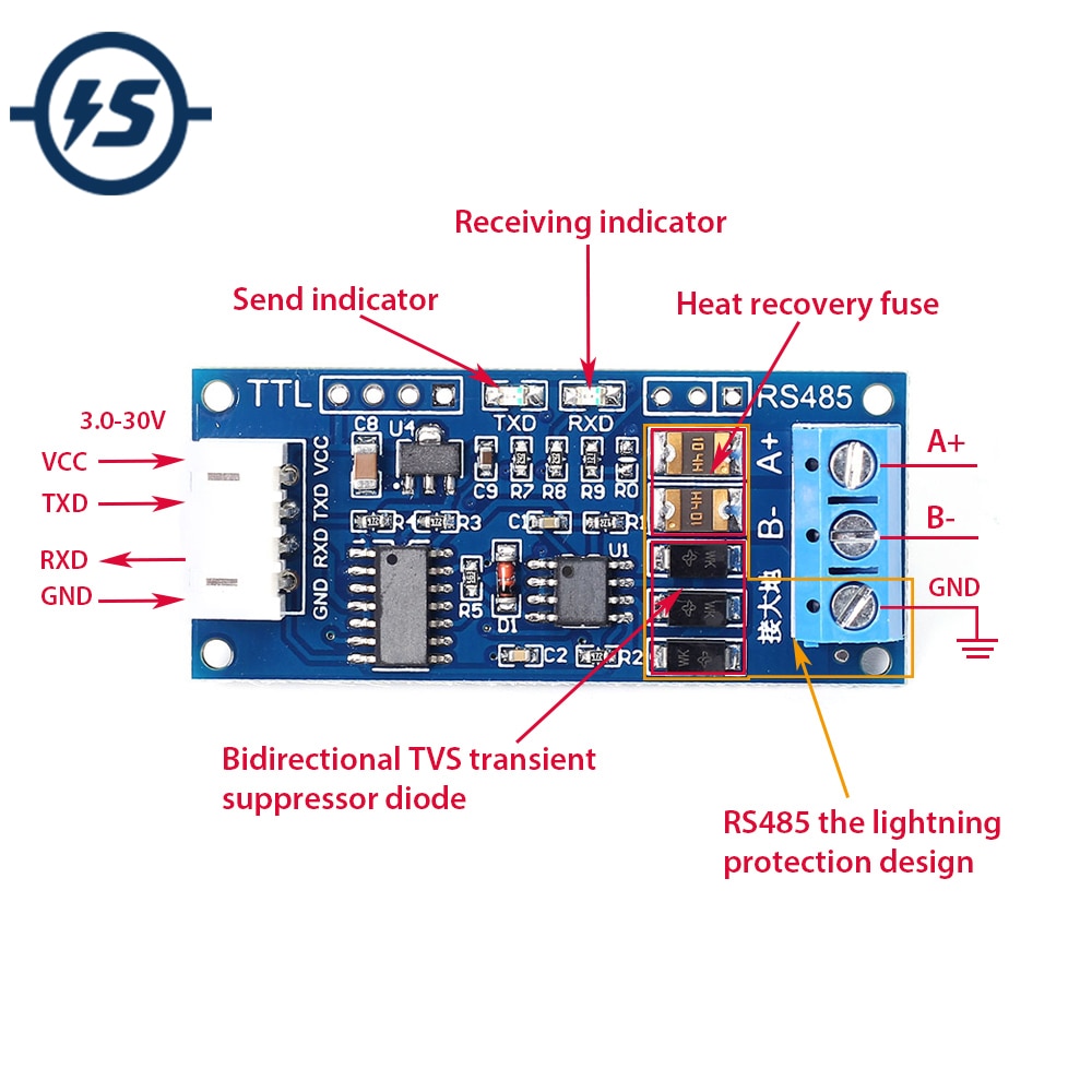
I use a serial port on a pc that can be configured as an RS485 in the BIOS. In any case you just need to connect the two data lines to the device, no other connection is needed.
As for which files are needed from the github site, it's probably the easiest to just download all of it and copy the whole lot into your linuxcnc config folder. I haven't whittled it down to the bare necessities yet but the folders 'micropython' and 'phy_fpga' can be deleted right away.
Getting the configuration right takes a few steps. First you need to get the .gsd (german) or .gse (english) files from the manufacturer website as these contain the required parameter settings for the device. (note that if you use the .gse file it will need to have the extension changed to .gsd). There are some demos for linuxcnc included. Basically the file 'pyprofibus.conf' needs to be modified to set up the profibus connection ( ie port and baudrate, bus address of all the slaves and the number of input and output bytes for each of them and the path to the respective .gsd files).
One problem was that the current version of 'pyprofibus' did not support devices that don't send data back to the master during communication. The valve block only sends an acknowledge byte back and that was not recognized as a response leading to timeouts and the master shutting down. I reached out to the author on his github page ,he's really quite responsive and helpful, and got it working.
To get everything hooked up to linuxcnc and hal you need to modify 'profibus.hal' and add it to your .ini then you run the startup script provided in the demo-folders and the relevant hal pins are created.
As usual things seem very logical in retrospect but it definitely involved a bit of a learning curve.
You can actually connect extension modules with up to 32inputs and 32outputs to that valve block, but I don't have any of those.
The author doesn't recommend using a usb to RS485 adapter, because of the time lags that can happen with USB, although I did quickly try with one and it seemed so be working well enough. The recommended way is to use an RS232 port with a TTL to RS485 adapter like this:
I use a serial port on a pc that can be configured as an RS485 in the BIOS. In any case you just need to connect the two data lines to the device, no other connection is needed.
As for which files are needed from the github site, it's probably the easiest to just download all of it and copy the whole lot into your linuxcnc config folder. I haven't whittled it down to the bare necessities yet but the folders 'micropython' and 'phy_fpga' can be deleted right away.
Getting the configuration right takes a few steps. First you need to get the .gsd (german) or .gse (english) files from the manufacturer website as these contain the required parameter settings for the device. (note that if you use the .gse file it will need to have the extension changed to .gsd). There are some demos for linuxcnc included. Basically the file 'pyprofibus.conf' needs to be modified to set up the profibus connection ( ie port and baudrate, bus address of all the slaves and the number of input and output bytes for each of them and the path to the respective .gsd files).
One problem was that the current version of 'pyprofibus' did not support devices that don't send data back to the master during communication. The valve block only sends an acknowledge byte back and that was not recognized as a response leading to timeouts and the master shutting down. I reached out to the author on his github page ,he's really quite responsive and helpful, and got it working.
To get everything hooked up to linuxcnc and hal you need to modify 'profibus.hal' and add it to your .ini then you run the startup script provided in the demo-folders and the relevant hal pins are created.
As usual things seem very logical in retrospect but it definitely involved a bit of a learning curve.
You can actually connect extension modules with up to 32inputs and 32outputs to that valve block, but I don't have any of those.
Attachments:
Last edit: 06 Oct 2021 06:24 by Aciera.
The following user(s) said Thank You: RotarySMP, tommylight
Please Log in or Create an account to join the conversation.
- andypugh
-

- Offline
- Moderator
-

Less
More
- Posts: 19871
- Thank you received: 4640
06 Oct 2021 13:22 #222355
by andypugh
Replied by andypugh on topic Linuxcnc and Profibus
What would be really cool would be a driver for the Mesa UART.
(And it _probably_ isn't all that hard to do)
(And it _probably_ isn't all that hard to do)
Please Log in or Create an account to join the conversation.
- Aciera
-
Topic Author
- Offline
- Administrator
-
Less
More
- Posts: 4734
- Thank you received: 2121
06 Oct 2021 13:42 - 06 Oct 2021 13:50 #222360
by Aciera
Replied by Aciera on topic Linuxcnc and Profibus
Yes, using the serial port the maximum speed is 19.2kbaud but with a mesa uart one might actually increase that towards the maximum of 12Mbaud preferably with the profibus stack being integrated into the FPGA.
[edit]
There is actually also a folder containing verilog code to intergrate a profibus stack on an FPGA.
github.com/mbuesch/pyprofibus/tree/master/phy_fpga
Just in case anybody is looking for a fun project.

[edit]
There is actually also a folder containing verilog code to intergrate a profibus stack on an FPGA.
github.com/mbuesch/pyprofibus/tree/master/phy_fpga
Just in case anybody is looking for a fun project.
Last edit: 06 Oct 2021 13:50 by Aciera.
Please Log in or Create an account to join the conversation.
- Aciera
-
Topic Author
- Offline
- Administrator
-
Less
More
- Posts: 4734
- Thank you received: 2121
20 Oct 2021 08:17 #223639
by Aciera
Replied by Aciera on topic Linuxcnc and Profibus
A little update on this. To try the extension capability I bought a 8 channel digital output module and a 16 channel digital input module to connect to the CPV valve block on ebay for less than 30$. All works quite nicely:
user-images.githubusercontent.com/460672...237-dad902cac355.mp4
For those interested I attach the zipped config folder:
user-images.githubusercontent.com/460672...237-dad902cac355.mp4
For those interested I attach the zipped config folder:
Attachments:
The following user(s) said Thank You: RotarySMP, 0x2102
Please Log in or Create an account to join the conversation.
- blauerklappstuhl
- Offline
- New Member
-

Less
More
- Posts: 18
- Thank you received: 6
08 Aug 2022 14:36 #249344
by blauerklappstuhl
Replied by blauerklappstuhl on topic Linuxcnc and Profibus
Hi! I am trying to get the same setup to work.pyprofibus is running, but no communication to the cpv is possible. Perhaps my output module is faulty(no Power led). But even with only the cpv connected I cant establish connection. Dip Switches set accordingly and modules in config delted and pins # tagged. I am using an usb to rs485 connector currently. Tomorrow an serial to rs485 adapter arrived. But I thought it should work a bit with usb(maybe Just some interruptions).
@Aciera: can you help me with troubleshooting?
Alex
@Aciera: can you help me with troubleshooting?
Alex
Please Log in or Create an account to join the conversation.
- Aciera
-
Topic Author
- Offline
- Administrator
-
Less
More
- Posts: 4734
- Thank you received: 2121
08 Aug 2022 15:31 #249350
by Aciera
Replied by Aciera on topic Linuxcnc and Profibus
First you will need to get the cpv module powered up. Do you have 24V on pin 1 and 0V on pin 3 of the 4-pin M12 connector?
Once you have that fixed you should launch linuxcnc from the terminal to get more debug information on what the profibus master is doing.
Once you have that fixed you should launch linuxcnc from the terminal to get more debug information on what the profibus master is doing.
Please Log in or Create an account to join the conversation.
- blauerklappstuhl
- Offline
- New Member
-
Less
More
- Posts: 18
- Thank you received: 6
08 Aug 2022 17:04 - 08 Aug 2022 17:12 #249355
by blauerklappstuhl
Replied by blauerklappstuhl on topic Linuxcnc and Profibus
Cpv has Power on logic and valve pin.red led is blinking once a second. [/code]
[/code]
; ----------------------------------------------- ;
;                                                 ;
; PROFIBUS configuration                          ;
;                                                 ;
; This file configures a pyprofibus instance.     ;
;                                                 ;
; ----------------------------------------------- ;


; General settings
[PROFIBUS]
; Enable/disable debug mode.
; 0 -> no debugging.
; 1 -> DP debugging.
; 2 -> DP and PHY debugging.
debug=2


; PHY protocol layer configuration
[PHY]

; The PHY layer driver type.
type=serial

; The PHY device name/path.
; Can be a device like /dev/ttyS0 or /dev/ttyAMA0 for 'serial'.
dev=/dev/ttyUSB1

; The Profibus on-wire baud rate.
baud=9600


; FDL protocol layer configuration
[FDL]


; DP protocol layer configuration
[DP]

; The master device class. Either 1 or 2.
master_class=1

; The Profibus address of this device.
master_addr=2


; ---
; Slave configurations
; Add as many [SLAVE_xxx] sections as needed.
; ---

; First slave configuration
[SLAVE_0]

; Optional slave name. Will be stored in slaveConf.name and slaveDesc.name.
; pyprofibus does not use the name internally.
name=cpv10

; This slave's Profibus address
addr=8

; The path to the GSD file.
gsd=cpv_0A35.gse

; Boolean: Sync mode enabled/available?
sync_mode=1

; Boolean: Freeze mode enabled/available?
freeze_mode=1

; 8 bit integer specifying the Profibus group ident mask.
group_mask=1

; This slave's watchdog timeout, in milliseconds.
watchdog_ms=300

; Module configuration.
; For each module plugged into the slave, add a module_xxx
; entry with the name of the module.
; The module name must match the name from the GSD file (approximately).
; The modules are used in the order of the index number.
module_0=Base module:16DO


; The number of output bytes this slave transmits to the
; master in Data_Exchange.
; This usually depends on the modules plugged into the slave.
output_size=2

; The number of input bytes this slave expects to receive
; in Data_Exchange.
; This usually depends on the modules plugged into the slave.
input_size=4

; Request and interpret a slave diagnosis every n Data_Exchange telegrams.
; n defaults to 0, which means: Never periodically request diagnosis.
; If periodic diagnosis is switched off, then diagnostic information will only be requested on faults.
; Note that input-only slaves (output_size=0) probably need a non-zero diag_period.
diag_period=0

[code]# --- Enable the used output pins ---
# All output pins are deactivated by default.
# So all output pins connected below, should be activated here by writing
# a '1' to the '.active' pin.
# Deactivated output pins will not be forwarded from LinuxCNC to the PROFIBUS.
setp    profibus.slave.8.output.bit.0.0.active        1
setp    profibus.slave.8.output.bit.0.2.active        1
setp    profibus.slave.8.output.bit.0.4.active        1
setp    profibus.slave.8.output.bit.0.6.active        1
setp    profibus.slave.8.output.bit.1.0.active        1
setp    profibus.slave.8.output.bit.1.2.active        1
setp    profibus.slave.8.output.bit.1.4.active        1
setp profibus.slave.8.output.bit.1.6.active 1cnc@cnc:~/linuxcnc/configs/BF20_MESA$ sh run-linuxcnc-demo.sh
LINUXCNC - 2.8.2
Machine configuration directory is '/home/cnc/linuxcnc/configs/BF20_MESA/.'
Machine configuration file is 'BF20_MESA.ini'
Starting LinuxCNC...
Found file(REL): ./BF20_MESA.hal
Note: Using POSIX realtime
hm2: loading Mesa HostMot2 driver version 0.15
hm2_pci: loading Mesa AnyIO HostMot2 driver version 0.7
hm2_pci: discovered 5i25 at 0000:03:00.0
hm2/hm2_5i25.0: Low Level init 0.15
hm2/hm2_5i25.0: Smart Serial Firmware Version 43
Board hm2_5i25.0.7i76.0.0 Hardware Mode 0 = standard
Board hm2_5i25.0.7i76.0.0 Software Mode 0 = io_spin
Board hm2_5i25.0.7i76.0.0 Software Mode 1 = io_ana_spin
Board hm2_5i25.0.7i76.0.0 Software Mode 2 = io_enc_ana_spin_fv
hm2/hm2_5i25.0: 34 I/O Pins used:
hm2/hm2_5i25.0: IO Pin 000 (P3-01): IOPort
hm2/hm2_5i25.0: IO Pin 001 (P3-14): IOPort
hm2/hm2_5i25.0: IO Pin 002 (P3-02): IOPort
hm2/hm2_5i25.0: IO Pin 003 (P3-15): IOPort
hm2/hm2_5i25.0: IO Pin 004 (P3-03): IOPort
hm2/hm2_5i25.0: IO Pin 005 (P3-16): IOPort
hm2/hm2_5i25.0: IO Pin 006 (P3-04): IOPort
hm2/hm2_5i25.0: IO Pin 007 (P3-17): IOPort
hm2/hm2_5i25.0: IO Pin 008 (P3-05): IOPort
hm2/hm2_5i25.0: IO Pin 009 (P3-06): IOPort
hm2/hm2_5i25.0: IO Pin 010 (P3-07): Muxed Encoder Select #2, pin Mux Select 0 (Output)
hm2/hm2_5i25.0: IO Pin 011 (P3-08): Muxed Encoder #1, pin Muxed A (Input)
hm2/hm2_5i25.0: IO Pin 012 (P3-09): Muxed Encoder #1, pin Muxed B (Input)
hm2/hm2_5i25.0: IO Pin 013 (P3-10): Muxed Encoder #1, pin Muxed Index (Input)
hm2/hm2_5i25.0: IO Pin 014 (P3-11): Muxed Encoder #2, pin Muxed A (Input)
hm2/hm2_5i25.0: IO Pin 015 (P3-12): Muxed Encoder #2, pin Muxed B (Input)
hm2/hm2_5i25.0: IO Pin 016 (P3-13): Muxed Encoder #2, pin Muxed Index (Input)
hm2/hm2_5i25.0: IO Pin 017 (P2-01): StepGen #0, pin Direction (Output)
hm2/hm2_5i25.0: IO Pin 018 (P2-14): StepGen #0, pin Step (Output)
hm2/hm2_5i25.0: IO Pin 019 (P2-02): StepGen #1, pin Direction (Output)
hm2/hm2_5i25.0: IO Pin 020 (P2-15): StepGen #1, pin Step (Output)
hm2/hm2_5i25.0: IO Pin 021 (P2-03): StepGen #2, pin Direction (Output)
hm2/hm2_5i25.0: IO Pin 022 (P2-16): StepGen #2, pin Step (Output)
hm2/hm2_5i25.0: IO Pin 023 (P2-04): StepGen #3, pin Direction (Output)
hm2/hm2_5i25.0: IO Pin 024 (P2-17): StepGen #3, pin Step (Output)
hm2/hm2_5i25.0: IO Pin 025 (P2-05): StepGen #4, pin Direction (Output)
hm2/hm2_5i25.0: IO Pin 026 (P2-06): StepGen #4, pin Step (Output)
hm2/hm2_5i25.0: IO Pin 027 (P2-07): Smart Serial Interface #0, pin tx0 (Output)
hm2/hm2_5i25.0: IO Pin 028 (P2-08): Smart Serial Interface #0, pin rx0 (Input)
hm2/hm2_5i25.0: IO Pin 029 (P2-09): IOPort
hm2/hm2_5i25.0: IO Pin 030 (P2-10): IOPort
hm2/hm2_5i25.0: IO Pin 031 (P2-11): Muxed Encoder #0, pin Muxed Index (Input)
hm2/hm2_5i25.0: IO Pin 032 (P2-12): Muxed Encoder #0, pin Muxed B (Input)
hm2/hm2_5i25.0: IO Pin 033 (P2-13): Muxed Encoder #0, pin Muxed A (Input)
hm2/hm2_5i25.0: registered
hm2_5i25.0: initialized AnyIO board at 0000:03:00.0
creating ladder-state
INFO CLASSICLADDER---I/O modbus master closed!
inifile: warning: File contains DOS-style line endings.
mb2hal parse_common_section DEBUG: [MB2HAL_INIT] [INIT_DEBUG] [3]
mb2hal parse_common_section DEBUG: [MB2HAL_INIT] [HAL_MODULE_NAME] [mb2hal]
mb2hal parse_common_section DEBUG: [MB2HAL_INIT] [SLOWDOWN] [0.000]
mb2hal parse_common_section DEBUG: [MB2HAL_INIT] [TOTAL_TRANSACTIONS] [3]
mb2hal parse_transaction_section DEBUG: [TRANSACTION_00] [LINK_TYPE] [serial] [0]
mb2hal parse_serial_subsection DEBUG: [TRANSACTION_00] [SERIAL_PORT] [/dev/RS485_FTDI]
mb2hal parse_serial_subsection DEBUG: [TRANSACTION_00] [SERIAL_BAUD] [9600]
mb2hal parse_serial_subsection DEBUG: [TRANSACTION_00] [SERIAL_BITS] [8]
mb2hal parse_serial_subsection DEBUG: [TRANSACTION_00] [SERIAL_PARITY] [none]
mb2hal parse_serial_subsection DEBUG: [TRANSACTION_00] [SERIAL_STOP] [1]
mb2hal parse_serial_subsection DEBUG: [TRANSACTION_00] [SERIAL_DELAY_MS] [6]
mb2hal parse_transaction_section DEBUG: [TRANSACTION_00] [MB_SLAVE_ID] [1]
mb2hal parse_transaction_section DEBUG: [TRANSACTION_00] [FIRST_ELEMENT] [8192]
mb2hal parse_transaction_section DEBUG: [TRANSACTION_00] [PIN_NAMES] [command]
mb2hal parse_transaction_section DEBUG: [TRANSACTION_00] [NELEMENTS] [1]
mb2hal parse_transaction_section DEBUG: [TRANSACTION_00] [MAX_UPDATE_RATE] [0.000]
mb2hal parse_transaction_section DEBUG: [TRANSACTION_00] [MB_RESPONSE_TIMEOUT_MS] [250]
INFO CLASSICLADDER---I/O modbus master Data bits 8 Stop bits 1 Parity 0
INFO CLASSICLADDER---I/O modbus master (Serial) init ok !
mb2hal parse_transaction_section DEBUG: [TRANSACTION_00] [MB_BYTE_TIMEOUT_MS] [250]
mb2hal parse_transaction_section DEBUG: [TRANSACTION_00] [DEBUG] [0]
mb2hal parse_transaction_section DEBUG: [TRANSACTION_00] [MB_TX_CODE] [fnct_06_write_single_register] [4]
mb2hal parse_transaction_section DEBUG: [TRANSACTION_00] [HAL_TX_NAME] [VFD_runmode]
mb2hal parse_ini_file OK: parse_transaction_section 0 OK
mb2hal parse_transaction_section DEBUG: [TRANSACTION_01] [LINK_TYPE] [serial] [0]
mb2hal parse_serial_subsection DEBUG: [TRANSACTION_01] [SERIAL_PORT] [/dev/RS485_FTDI]
mb2hal parse_serial_subsection DEBUG: [TRANSACTION_01] [SERIAL_BAUD] [9600]
mb2hal parse_serial_subsection DEBUG: [TRANSACTION_01] [SERIAL_BITS] [8]
mb2hal parse_serial_subsection DEBUG: [TRANSACTION_01] [SERIAL_PARITY] [none]
mb2hal parse_serial_subsection DEBUG: [TRANSACTION_01] [SERIAL_STOP] [1]
mb2hal parse_serial_subsection DEBUG: [TRANSACTION_01] [SERIAL_DELAY_MS] [6]
mb2hal parse_transaction_section DEBUG: [TRANSACTION_01] [MB_SLAVE_ID] [1]
mb2hal parse_transaction_section DEBUG: [TRANSACTION_01] [FIRST_ELEMENT] [4096]
mb2hal parse_transaction_section DEBUG: [TRANSACTION_01] [PIN_NAMES] [frequency]
mb2hal parse_transaction_section DEBUG: [TRANSACTION_01] [NELEMENTS] [1]
mb2hal parse_transaction_section DEBUG: [TRANSACTION_01] [MAX_UPDATE_RATE] [0.000]
mb2hal parse_transaction_section DEBUG: [TRANSACTION_01] [MB_RESPONSE_TIMEOUT_MS] [250]
mb2hal parse_transaction_section DEBUG: [TRANSACTION_01] [MB_BYTE_TIMEOUT_MS] [250]
mb2hal parse_transaction_section DEBUG: [TRANSACTION_01] [DEBUG] [0]
mb2hal parse_transaction_section DEBUG: [TRANSACTION_01] [MB_TX_CODE] [fnct_06_write_single_register] [4]
mb2hal parse_transaction_section DEBUG: [TRANSACTION_01] [HAL_TX_NAME] [VFD_write]
mb2hal parse_ini_file OK: parse_transaction_section 1 OK
mb2hal parse_transaction_section DEBUG: [TRANSACTION_02] [LINK_TYPE] [serial] [0]
mb2hal parse_serial_subsection DEBUG: [TRANSACTION_02] [SERIAL_PORT] [/dev/RS485_FTDI]
mb2hal parse_serial_subsection DEBUG: [TRANSACTION_02] [SERIAL_BAUD] [9600]
mb2hal parse_serial_subsection DEBUG: [TRANSACTION_02] [SERIAL_BITS] [8]
mb2hal parse_serial_subsection DEBUG: [TRANSACTION_02] [SERIAL_PARITY] [none]
mb2hal parse_serial_subsection DEBUG: [TRANSACTION_02] [SERIAL_STOP] [1]
mb2hal parse_serial_subsection DEBUG: [TRANSACTION_02] [SERIAL_DELAY_MS] [6]
mb2hal parse_transaction_section DEBUG: [TRANSACTION_02] [MB_SLAVE_ID] [1]
mb2hal parse_transaction_section DEBUG: [TRANSACTION_02] [FIRST_ELEMENT] [4099]
mb2hal parse_transaction_section DEBUG: [TRANSACTION_02] [PIN_NAMES] [voltage,ampere]
mb2hal parse_transaction_section DEBUG: [TRANSACTION_02] [NELEMENTS] [2]
mb2hal parse_transaction_section DEBUG: [TRANSACTION_02] [MAX_UPDATE_RATE] [0.000]
mb2hal parse_transaction_section DEBUG: [TRANSACTION_02] [MB_RESPONSE_TIMEOUT_MS] [250]
mb2hal parse_transaction_section DEBUG: [TRANSACTION_02] [MB_BYTE_TIMEOUT_MS] [250]
mb2hal parse_transaction_section DEBUG: [TRANSACTION_02] [DEBUG] [0]
mb2hal parse_transaction_section DEBUG: [TRANSACTION_02] [MB_TX_CODE] [fnct_03_read_holding_registers] [2]
mb2hal parse_transaction_section DEBUG: [TRANSACTION_02] [HAL_TX_NAME] [VFD_power]
mb2hal parse_ini_file OK: parse_transaction_section 2 OK
mb2hal main OK: parse_ini_file done OK
mb2hal init_mb_links DEBUG: LINK 0 (RTU) link_type[0] device[/dev/RS485_FTDI] baud[9600] data[8] parity[N] stop[1] fd[-1]
mb2hal main OK: init_gbl.mb_link done OK
mb2hal init_mb_tx DEBUG: MB_TX 0 lk_n[0] tx_n[0] cfg_dbg[0] lk_dbg[0] t_inc[0.000] nxt_t[0.000]
mb2hal init_mb_tx DEBUG: MB_TX 1 lk_n[0] tx_n[1] cfg_dbg[0] lk_dbg[0] t_inc[0.000] nxt_t[0.000]
mb2hal init_mb_tx DEBUG: MB_TX 2 lk_n[0] tx_n[2] cfg_dbg[0] lk_dbg[0] t_inc[0.000] nxt_t[0.000]
mb2hal main OK: init_gbl.mb_tx done OK
mb2hal create_each_mb_tx_hal_pins DEBUG: mb_tx_num [0] pin_name [mb2hal.VFD_runmode.num_errors]
mb2hal create_each_mb_tx_hal_pins DEBUG: mb_tx_num [0] pin_name [mb2hal.VFD_runmode.command]
mb2hal create_each_mb_tx_hal_pins DEBUG: mb_tx_num [1] pin_name [mb2hal.VFD_write.num_errors]
mb2hal create_each_mb_tx_hal_pins DEBUG: mb_tx_num [1] pin_name [mb2hal.VFD_write.frequency]
mb2hal create_each_mb_tx_hal_pins DEBUG: mb_tx_num [2] pin_name [mb2hal.VFD_power.num_errors]
mb2hal create_each_mb_tx_hal_pins DEBUG: mb_tx_num [2] pin_name [mb2hal.VFD_power.voltage]
mb2hal create_each_mb_tx_hal_pins DEBUG: mb_tx_num [2] pin_name [mb2hal.VFD_power.ampere]
mb2hal main OK: HAL components created OK
mb2hal main OK: Link thread loop and logic 0 created OK
mb2hal main OK: mb2hal is running
Found file(REL): ./profibus.hal
GSD parser warning in 'cpv_0A35.gse' at line 14:
FMS_supp = 0
--> Ignored unknown line
GSD parser warning in 'cpv_0A35.gse' at line 63:
Unit_Diag_Bit(8) = "CPI-connection to output modul"
--> Ignored unknown line
GSD parser warning in 'cpv_0A35.gse' at line 64:
Unit_Diag_Bit(9) = "CPI-connection to input modul"
--> Ignored unknown line
GSD parser warning in 'cpv_0A35.gse' at line 65:
Unit_Diag_Bit(10) = "short circuit / overload output"
--> Ignored unknown line
GSD parser warning in 'cpv_0A35.gse' at line 66:
Unit_Diag_Bit(11) = "power load failure output module"
--> Ignored unknown line
GSD parser warning in 'cpv_0A35.gse' at line 67:
Unit_Diag_Bit(12) = "sensor power supply < 10V"
--> Ignored unknown line
GSD parser warning in 'cpv_0A35.gse' at line 68:
Unit_Diag_Bit(13) = "valve power supply < 20.4V"
--> Ignored unknown line
GSD parser warning in 'cpv_0A35.gse' at line 69:
Unit_Diag_Bit(14) = "valve power supply < 10V"
--> Ignored unknown line
GSD parser warning in 'cpv_0A35.gse' at line 70:
Unit_Diag_Bit(15) = "no update-mode"
--> Ignored unknown line
GSD parser warning in 'cpv_0A35.gse' at line 71:
Unit_Diag_Bit(16) = "failure main module"
--> Ignored unknown line
GSD parser warning in 'cpv_0A35.gse' at line 72:
Unit_Diag_Bit(17) = "failure 1. CP- module"
--> Ignored unknown line
GSD parser warning in 'cpv_0A35.gse' at line 73:
Unit_Diag_Bit(18) = "failure 2. CP- module"
--> Ignored unknown line
GSD parser warning in 'cpv_0A35.gse' at line 74:
Unit_Diag_Bit(19) = "failure 3. CP- module"
--> Ignored unknown line
GSD parser warning in 'cpv_0A35.gse' at line 75:
Unit_Diag_Bit(20) = "failure 4. CP- module"
--> Ignored unknown line
GSD parser warning in 'cpv_0A35.gse' at line 95:
Bit(1) 1 0-1
--> Ignored unknown line
GSD parser warning in 'cpv_0A35.gse' at line 100:
Bit(7) 1 0-1
--> Ignored unknown line
GSD parser warning in 'cpv_0A35.gse' at line 105:
BitArea(0-1) 0 0-2
--> Ignored unknown line
GSD parser warning in 'cpv_0A35.gse' at line 110:
unsigned8 0 0-255
--> Ignored unknown line
GSD parser warning in 'cpv_0A35.gse' at line 114:
unsigned16 0 0-65535
--> Ignored unknown line
GSD parser warning in 'cpv_0A35.gse' at line 118:
unsigned32 0 0-16777215
--> Ignored unknown line
GSD parser warning in 'cpv_0A35.gse' at line 122:
unsigned32 0 0-4294967295
--> Ignored unknown line
GSD parser warning in 'cpv_0A35.gse' at line 126:
unsigned8 91 0-255
--> Ignored unknown line
GSD parser warning in 'cpv_0A35.gse' at line 132:
Info_Text = "Base unit CPV-SC with 16 digital outputs (valve coils)"
--> Ignored unknown line
GSD parser warning in 'cpv_0A35.gse' at line 133:
1
--> Ignored unknown line
GSD parser warning in 'cpv_0A35.gse' at line 143:
Info_Text = "String extension with 8 digital outputs"
--> Ignored unknown line
GSD parser warning in 'cpv_0A35.gse' at line 144:
2
--> Ignored unknown line
GSD parser warning in 'cpv_0A35.gse' at line 153:
Info_Text = "String extension with 16 digital outputs"
(classicladder:20624): Gtk-CRITICAL **: 19:08:56.053: IA__gtk_widget_get_parent: assertion 'GTK_IS_WIDGET (widget)' failed
--> Ignored unknown line
GSD parser warning in 'cpv_0A35.gse' at line 154:
3
--> Ignored unknown line
GSD parser warning in 'cpv_0A35.gse' at line 163:
Info_Text = "String extension with 24 digital outputs"
--> Ignored unknown line
GSD parser warning in 'cpv_0A35.gse' at line 164:
4
--> Ignored unknown line
GSD parser warning in 'cpv_0A35.gse' at line 173:
Info_Text = "String extension with 32 digital outputs"
--> Ignored unknown line
GSD parser warning in 'cpv_0A35.gse' at line 174:
5
--> Ignored unknown line
GSD parser warning in 'cpv_0A35.gse' at line 183:
Info_Text = "String extension with 8 digital inputs"
--> Ignored unknown line
GSD parser warning in 'cpv_0A35.gse' at line 184:
6
--> Ignored unknown line
GSD parser warning in 'cpv_0A35.gse' at line 191:
Info_Text = "String extension with 16 digital inputs"
--> Ignored unknown line
GSD parser warning in 'cpv_0A35.gse' at line 192:
7
--> Ignored unknown line
GSD parser warning in 'cpv_0A35.gse' at line 199:
Info_Text = "String extension with 24 digital inputs"
--> Ignored unknown line
GSD parser warning in 'cpv_0A35.gse' at line 200:
8
--> Ignored unknown line
GSD parser warning in 'cpv_0A35.gse' at line 207:
Info_Text = "String extension with 32 digital inputs"
--> Ignored unknown line
GSD parser warning in 'cpv_0A35.gse' at line 208:
9
--> Ignored unknown line
GSD parser warning in 'cpv_0A35.gse' at line 215:
Info_Text = "tool change mode with 32 inputs and 32 outputs"
--> Ignored unknown line
GSD parser warning in 'cpv_0A35.gse' at line 216:
10
--> Ignored unknown line
pyprofibus: DP slave 8 output: 2 bytes
pyprofibus: DP slave 8 input: 4 bytes
Warning in GSD 'cpv_0A35.gse': DPv1 User_Prm_Data override ignored
pyprofibus: Running PROFIBUS-DP master...
pyprofibus: ready.
Found file(REL): ./custom.hal
Found file(REL): ./chinahandrad.hal
pyprofibus: Active DP slave (addr=8) pins:
pyprofibus: DP slave input: profibus.slave.8.output.bit.0.0
pyprofibus: DP slave input: profibus.slave.8.output.bit.0.2
pyprofibus: DP slave input: profibus.slave.8.output.bit.0.4
pyprofibus: DP slave input: profibus.slave.8.output.bit.0.6
pyprofibus: DP slave input: profibus.slave.8.output.bit.1.0
pyprofibus: DP slave input: profibus.slave.8.output.bit.1.2
pyprofibus: DP slave input: profibus.slave.8.output.bit.1.4
pyprofibus: DP slave input: profibus.slave.8.output.bit.1.6
pyprofibus: HAL configuration done
DPM1: Trying to initialize slave 8...
PHY-serial: TX 10 08 02 49 53 16
PHY-serial: RX 10 02 08 00 0A 16
DPM1: slave[08].state --> 'wait for diag'
DPM1: Requesting Slave_Diag from slave 8...
PHY-serial: TX 68 05 05 68 88 82 6D 3C 3E F1 16
PHY-serial: RX 68 0B 0B 68 82 88 08 3E 3C 02 05 00 FF 00 C9 5B 16
DPM1: slave[08].state --> 'wait for Prm'
DPM1: Sending Set_Prm to slave 8...
PHY-serial: TX 68 13 13 68 88 82 5D 3D 3E B8 1E 01 00 0A 35 01 00 00 00 82 00 00 00 7B 16
PHY-serial: RX 10 02 08 02 0C 16
[qtpyvcp][INFO] Logging to /home/cnc/qtpyvcp.log (logger.py:97)
[qtpyvcp][INFO] QtPyVCP Version: v0.3.19 (opt_parser.py:199)
PHY-serial: TX 68 13 13 68 88 82 7D 3D 3E B8 1E 01 00 0A 35 01 00 00 00 82 00 00 00 9B 16
PHY-serial: RX 10 02 08 02 0C 16
DPM1: State machine timeout! Trying to re-initializing slave 8...
DPM1: Trying to initialize slave 8...
PHY-serial: TX 10 08 02 49 53 16
PHY-serial: RX 10 02 08 00 0A 16
DPM1: slave[08].state --> 'wait for diag'
DPM1: Requesting Slave_Diag from slave 8...
PHY-serial: TX 68 05 05 68 88 82 7D 3C 3E 01 16
PHY-serial: RX 68 0B 0B 68 82 88 08 3E 3C 02 05 00 FF 00 C9 5B 16
DPM1: slave[08].state --> 'wait for Prm'
DPM1: Sending Set_Prm to slave 8...
PHY-serial: TX 68 13 13 68 88 82 5D 3D 3E B8 1E 01 00 0A 35 01 00 00 00 82 00 00 00 7B 16
PHY-serial: RX 10 02 08 02 0C 16
PHY-serial: TX 68 13 13 68 88 82 7D 3D 3E B8 1E 01 00 0A 35 01 00 00 00 82 00 00 00 9B 16
PHY-serial: RX 10 02 08 02 0C 16
DPM1: State machine timeout! Trying to re-initializing slave 8...
DPM1: Trying to initialize slave 8...[code]
Last edit: 08 Aug 2022 17:12 by blauerklappstuhl.
Please Log in or Create an account to join the conversation.
- Aciera
-
Topic Author
- Offline
- Administrator
-
Less
More
- Posts: 4734
- Thank you received: 2121
08 Aug 2022 19:11 - 08 Aug 2022 19:13 #249361
by Aciera
Replied by Aciera on topic Linuxcnc and Profibus
Ok, so they are talking.
I noticed that in your pyprofibus.conf you have:
Which is incorrect. Since you have only the base module (with 16 digital out) your slave transmits 0 bytes to the master and expects to receive only 2 bytes from the master.
So try changing the above section to this:
I noticed that in your pyprofibus.conf you have:
; The number of output bytes this slave transmits to the
; master in Data_Exchange.
; This usually depends on the modules plugged into the slave.
output_size=2

; The number of input bytes this slave expects to receive
; in Data_Exchange.
; This usually depends on the modules plugged into the slave.
input_size=4
Which is incorrect. Since you have only the base module (with 16 digital out) your slave transmits 0 bytes to the master and expects to receive only 2 bytes from the master.
So try changing the above section to this:
; The number of output bytes this slave transmits to the
; master in Data_Exchange.
; This usually depends on the modules plugged into the slave.
output_size=0

; The number of input bytes this slave expects to receive
; in Data_Exchange.
; This usually depends on the modules plugged into the slave.
input_size=2
Last edit: 08 Aug 2022 19:13 by Aciera. Reason: editor mess
The following user(s) said Thank You: tommylight
Please Log in or Create an account to join the conversation.
Time to create page: 0.441 seconds