Retrofitting a 1986 Maho MH400E
- RotarySMP
-
 Topic Author
- Offline
- Platinum Member
-

Less
More
- Posts: 1633
- Thank you received: 595
23 May 2019 13:16 #134692
by RotarySMP
Replied by RotarySMP on topic Retrofitting a 1986 Maho MH400E
If you are willing to play the lottery...
www.ebay.at/itm/Fashion-Heavy-Duty-Indus...d:g:RzYAAOSwxN5WYPwu
www.ebay.at/itm/Fashion-Heavy-Duty-Indus...d:g:RzYAAOSwxN5WYPwu
Please Log in or Create an account to join the conversation.
- Glemigobles
- Offline
- Elite Member
-

Less
More
- Posts: 201
- Thank you received: 18
23 May 2019 14:59 #134708
by Glemigobles
Replied by Glemigobles on topic Retrofitting a 1986 Maho MH400E
An electronics store here has one for ca. 50+€, if I was to get a footswitch I'd prefer being able to send it back easily in case it proved defective.
Please Log in or Create an account to join the conversation.
- Glemigobles
- Offline
- Elite Member
-
Less
More
- Posts: 201
- Thank you received: 18
23 May 2019 17:13 #134722
by Glemigobles
Replied by Glemigobles on topic Retrofitting a 1986 Maho MH400E
Mark, if you're still interested in the tuning part of the retrofit, here's the manual for my version of the control from the Heidenhain website:
product.heidenhain.de/JPBC/image/FILEBAS...e%20482287320331.pdf
You have my machine constants earlier in the thread. I haven't yet read this manual, but positions 215-217 are following errors used for determining gain on axis X and nod point, and position 219 is an acceleration time constant in miliseconds.
When I have the time to read up on what these values imply I might have a go at another tuning session.
Please Log in or Create an account to join the conversation.
- Glemigobles
- Offline
- Elite Member
-
Less
More
- Posts: 201
- Thank you received: 18
24 May 2019 17:12 #134832
by Glemigobles
Replied by Glemigobles on topic Retrofitting a 1986 Maho MH400E
Finally got my first full program to run, cutting 30 parts using o-code subroutines. It's loud as hell with the MAHO spindle running at full blast, but the 3d toolpaths now allow easy entry into the material and I expect my endmills will last longer vs plunging.
One of the best purchases in the past few months for me was a pair of Etymotic ER4XR earphones. They have excellent isolation, and not only do they save my ears, but have great sound. When I play music, the noise of the machine is only faintly audible. I highly recommend them in place of ear defenders. 1) you don't mind them when it's warm/hot 2) they don't tire my ears 3) they're awesome earphones that I use all the time outside of the workshop as well.
One of the best purchases in the past few months for me was a pair of Etymotic ER4XR earphones. They have excellent isolation, and not only do they save my ears, but have great sound. When I play music, the noise of the machine is only faintly audible. I highly recommend them in place of ear defenders. 1) you don't mind them when it's warm/hot 2) they don't tire my ears 3) they're awesome earphones that I use all the time outside of the workshop as well.
Please Log in or Create an account to join the conversation.
- RotarySMP
-
Topic Author
- Offline
- Platinum Member
-
Less
More
- Posts: 1633
- Thank you received: 595
25 May 2019 14:21 - 25 May 2019 15:57 #134895
by RotarySMP
Replied by RotarySMP on topic Retrofitting a 1986 Maho MH400E
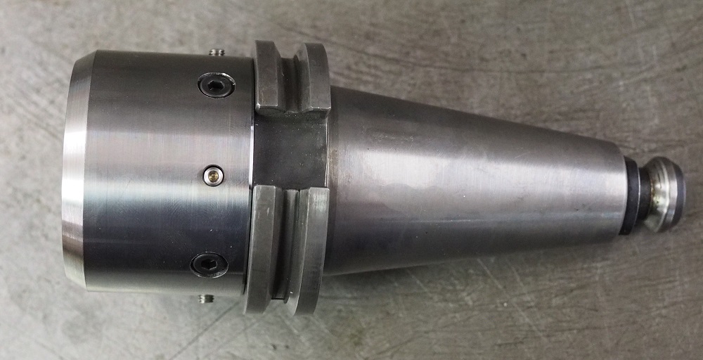
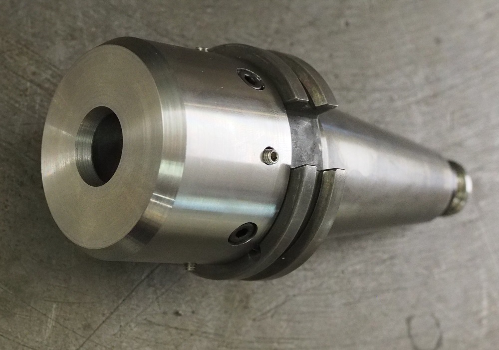
Made some more progress on the housing for my 3D probe.
I took a look through the Phillips set up instructions you sent, but so far the light bulb hasn't gone on yet, on how to use that information in LinuxCNC. Here are the machine constants from your machines X-Axis.
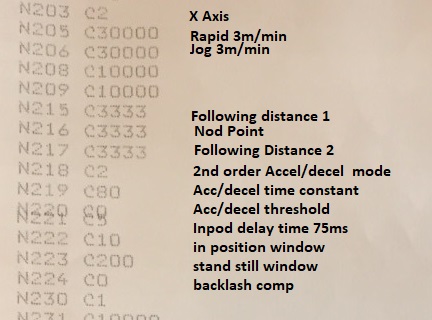
The Phillips manual gives you graphs for working out the gain to be entered in 215 based on the Kv (Gain factor) of the servo system. Did you find a the appropriate Kv for your Indramat system, or just use the recommended default of 0.5?
Given 3m/min rapid, and the default Kv of 0.5, I get an Mc value of 7000, which the Phillips would have served as a starting point for tuning the drives. How does Phillips Mc = 7000 correlate to the P,I,D,FF1, FF2 terms applicable to LinuxCNC?
I have been running my Maho today with 3m/mm rapids, and 220 acceleration. P is about 5.5, I =0 d=0 with FF1 = 0.2 and FF2 around 0.002. The machine is extremely responsive, but the following errors seen on the HALscope are horrible (up to 1mm on rapids). I have tried following the servo tuning instructions Andy linked, which worked really well when I had low acceleration of 45 set. Now I upped that 5X, to the low end of the Indramats recommended range, I get pretty massive following errors (20µm) even at very low feed rates around 50 mm/min.
I also use ear defenders when working on the MAHO.
Mark
I took a look through the Phillips set up instructions you sent, but so far the light bulb hasn't gone on yet, on how to use that information in LinuxCNC. Here are the machine constants from your machines X-Axis.
The Phillips manual gives you graphs for working out the gain to be entered in 215 based on the Kv (Gain factor) of the servo system. Did you find a the appropriate Kv for your Indramat system, or just use the recommended default of 0.5?
Given 3m/min rapid, and the default Kv of 0.5, I get an Mc value of 7000, which the Phillips would have served as a starting point for tuning the drives. How does Phillips Mc = 7000 correlate to the P,I,D,FF1, FF2 terms applicable to LinuxCNC?
I have been running my Maho today with 3m/mm rapids, and 220 acceleration. P is about 5.5, I =0 d=0 with FF1 = 0.2 and FF2 around 0.002. The machine is extremely responsive, but the following errors seen on the HALscope are horrible (up to 1mm on rapids). I have tried following the servo tuning instructions Andy linked, which worked really well when I had low acceleration of 45 set. Now I upped that 5X, to the low end of the Indramats recommended range, I get pretty massive following errors (20µm) even at very low feed rates around 50 mm/min.
I also use ear defenders when working on the MAHO.
Mark
Last edit: 25 May 2019 15:57 by RotarySMP.
Please Log in or Create an account to join the conversation.
- RotarySMP
-
Topic Author
- Offline
- Platinum Member
-
Less
More
- Posts: 1633
- Thank you received: 595
25 May 2019 18:24 - 25 May 2019 18:32 #134912
by RotarySMP
Replied by RotarySMP on topic Retrofitting a 1986 Maho MH400E
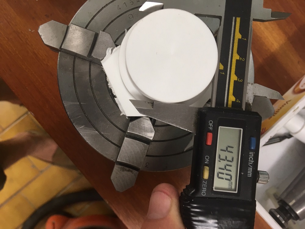
The next component I need to make on the 3D Touch probe requires plunging an 8mm HSS ball end mill 4mm deep into plastic. Not sure what plastic, it was an off cut from the metal supermarket.
What is a good feed and speed for a job like that please?
Mark
What is a good feed and speed for a job like that please?
Mark
Attachments:
Last edit: 25 May 2019 18:32 by RotarySMP.
Please Log in or Create an account to join the conversation.
- Glemigobles
- Offline
- Elite Member
-
Less
More
- Posts: 201
- Thank you received: 18
25 May 2019 19:20 - 25 May 2019 19:28 #134919
by Glemigobles
Replied by Glemigobles on topic Retrofitting a 1986 Maho MH400E
Well, actually the type of plastic is very important. Some are very forgiving, others are a bear to machine.
If you don't know, you should make some test cuts. I've never used an HSS cutter for plastic, the ones with the good geometry are usually carbide. It might be a a better strategy to use a 3d toolpath with a smaller end mill, depending on the plastic it could give you a much better surface finish.
Is this a chunk of material or sheet stock? Are you going to hold it in a vise?
To cut sheet stock I use a special type of double-sided tape from 3M. John Saunders from NYCCNC has a similar trick, but he uses two layers of one-sided tape, glued together with super glue. It requires a spray-on activator, but is a very versatile work holding technique, sort of a vacuum chuck alternative with no worries about loosing grip when machining holes. Here's a link to his technique:
www.nyccnc.com/super-glue-fixturing/
Neither he nor I apply the tape directly to the machine table.
EDIT: as a general rule, if you're cutting a thermoplastic material, your feed and chip evacuation will play a crucial role in the result. If the feed is too low, or the chips have nowhere to go, they will melt, form a solid blob of plastic on your cutter and it will break. However, IME, chip evacuation is almost entirely down to cutter geometry. Blowing air or coolant on the part will help some, but if your feed is too low in relation to the spindle speed, eventually everything will go to sh#t.
The way to look at setting parameters for cutting thermoplastics is by the relation between the spindle rpm and feed rate. The feed rate has to be high (much higher than in metal). Thermoset resins are completely different are far easier to machine because they won't melt. These include e.g. polyurethanes, epoxies and some acrylics (NOT PMMA, aka plexiglass, which is a thermoplastic). Tooling boards are made of filler infused with thermoset resins and can be machined at insane feeds. But they're rather expensive.
Last edit: 25 May 2019 19:28 by Glemigobles.
Please Log in or Create an account to join the conversation.
- RotarySMP
-
Topic Author
- Offline
- Platinum Member
-
Less
More
- Posts: 1633
- Thank you received: 595
25 May 2019 19:44 - 25 May 2019 19:53 #134922
by RotarySMP
Replied by RotarySMP on topic Retrofitting a 1986 Maho MH400E
Thanks. Work holding is not an issue in this case. It is chunk, probably a thermo plastic. I will keep it mounted in the lathe chuck, and clamp that to the mill table during milling, to maintain the concentrically for when I put it back on the lathe and part it off.
Good suggestion on taking a test cut. When I was turning it, it seemed pretty easy to cut, giving a good surface finish over a range of feeds (all pretty fast) at 1800rpm. I haven't bored out the core yet, so I can do some test cuts there. It is a new, name brand two flute ball end mill, so I'll try plunging it at 4000rpm and a high feed rate like 800mm/min.
If that doesn't work, think the smallest ball end mill I have is about 4mm, so I could try 3D milling with that.
Last edit: 25 May 2019 19:53 by RotarySMP.
Please Log in or Create an account to join the conversation.
- andypugh
-

- Offline
- Moderator
-

Less
More
- Posts: 19879
- Thank you received: 4643
25 May 2019 21:39 #134932
by andypugh
Replied by andypugh on topic Retrofitting a 1986 Maho MH400E
I am not going to get it published in time, but I have an idea for a touch-probe that needs much less accurate machining than the 6-ball type.
(well, its's an idea I stole from Zeiss, actually, but it means that you can make a pretty good probe with a drill press and a hexagonal collet block. Or a 4th axis if you have one.)
The idea is to use the intersection of the axes of holes as the reference geometry rather than the depth of dimples. The balls are replaced with ground dowel pins.
photos.app.goo.gl/gspx8Xw7nuDsBHY69
The following user(s) said Thank You: Todd Zuercher, drimaropoylos
Please Log in or Create an account to join the conversation.
- RotarySMP
-
Topic Author
- Offline
- Platinum Member
-
Less
More
- Posts: 1633
- Thank you received: 595
26 May 2019 06:51 - 26 May 2019 13:16 #134983
by RotarySMP
Replied by RotarySMP on topic Retrofitting a 1986 Maho MH400E
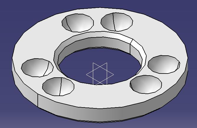
Thanks for sharing that. It is food for thought, but would require a complete restart, as my housing is short and fat, without enough length to fit that. The probe carrier is the same for both methods. A bar with three pins at 120°.
So for that Zeiss method, you would set up the rotary table on an angle plate, find center of the angled blank, offset it, go around three times
1/ mill flats so the drill starts don't wander,
2/ drill and
3/ ream three holes, then adjust the angle plate, recenter, and repeat.
- two multi axis set up operations, and 18 machining operations.
Verses
clamp down the lathe chuck, find center and run six lines of code to punge the ball mill.
G90 G81 X0 Y16 Z-4 R10
X-9.18 Y13.11
X-13.96 Y-8
X-6.76 Y-14.75
X13.86 Y-8
X15.94 Y1.39
I am a lot more confident in the Maho's ability to hit the same depth 6 times, on six locations, in a single set up based on the lathe chucks parallelism, than I am in my ability to accurately set up and execute the Zeiss version.
I hope that the ball spacing and height errors will contribute less to inaccuracy than other features I already have.
From what I have seen so far, the stack of threads (Renishaw stylus--> Adaptor --> center body) could be a source of run out. I would have liked to use a more rigid insulation material like Corian, but couldn't find any. The plastic I have doesn't repeat well in collets, so I inserted the threaded brass insert, to be able to mount it on a mandrel for finish turning it, and for drilling the 120° holes. M3 would not have been strong enough, so I went for M5 as you can also get Stylus in M5, but then this M3 stylus with carbide shaft was too good to refuse.
The next issue is going to be centering and mounting the ball carrier in the housing, without tilt, which is why I want to do all machining in the one chuck set up, including parting. I hope mounting the head onto the 40 taper shank with four opposing clamping screws gives me enough adjustment to compensate for my machining sins.
EDIT: I was thinking a bit more about that Zeiss design. Both this and the six ball version are static indeterminate, and therefore dependant on high precision and some deformation to get electrical continuity through the whole system. The narrowed angle between the pins could be matched by increased ball spacing. When you machine yours, please post pictures of the set up. I guess it can be done without changing the angle plate angle, by just moving across and rotating 120°. How would you set up the angle if you use a hex block instead of a rotary table on an angle plate?
Last edit: 26 May 2019 13:16 by RotarySMP.
Please Log in or Create an account to join the conversation.
Moderators: piasdom
Time to create page: 0.543 seconds