Retrofitting a 1986 Maho MH400E
- hanmon
- Offline
- Senior Member
-

Less
More
- Posts: 73
- Thank you received: 23
15 Jan 2019 22:38 #124271
by hanmon
Replied by hanmon on topic Retrofitting a 1986 Maho MH400E
Hi there,
Mark "convinced" me to join this forum and post my 2 cents.
After swapping the EXEs the drift showed up on the other axis.
This tells me that all other components involved like 3TRM, glass scale, etc. work faultlessly and the cause must be the EXE itself.
The deviation increases after a few minutes or in other words with warming up components.
I do not have the schematics at hand but from former repairs on PCBs I assume that a (Tantal/Filter) Capacitor is defective. They tend to leak and bypass and increase current draw/voltage drop over time.
Could you please measure the current (over time) on 12V and 5V, Mark ?
Regards,
Hanno
FYI: I'm retrofitting a MH400E build in 1986 as well
Please Log in or Create an account to join the conversation.
- RotarySMP
-
 Topic Author
- Offline
- Platinum Member
-

Less
More
- Posts: 1627
- Thank you received: 595
16 Jan 2019 15:14 #124291
by RotarySMP
Replied by RotarySMP on topic Retrofitting a 1986 Maho MH400E
Thanks Hanno. Welcome.
I am not sure If I'll get time to do this today, but will get try an get the current measurement as soon as possible.
Mark
I am not sure If I'll get time to do this today, but will get try an get the current measurement as soon as possible.
Mark
Please Log in or Create an account to join the conversation.
- RotarySMP
-
Topic Author
- Offline
- Platinum Member
-
Less
More
- Posts: 1627
- Thank you received: 595
16 Jan 2019 15:20 #124292
by RotarySMP
Replied by RotarySMP on topic Retrofitting a 1986 Maho MH400E
And Hanno, we look forward to photos of your MAHO.
Mark
Mark
Please Log in or Create an account to join the conversation.
- hanmon
- Offline
- Senior Member
-
Less
More
- Posts: 73
- Thank you received: 23
17 Jan 2019 06:28 #124329
by hanmon
Replied by hanmon on topic Retrofitting a 1986 Maho MH400E
Hi Mark,
nothing spectacular, yet.
Wired up the relays for a first test on the weekend and color coded the servo controller wires.
As you already mentioned in an email, every MAHO is different.
I have this cooling unit mounted in the cabinet door, therefore the relay PCB is located in the lower right corner rotated by 90°.
As you can see, I installed an additional 7I74 Eight Channel RS-422/485 interface which connects with the
7I84 Isolated remote field I/O card and a 7I73 Pendant/control panel interface which will be located in the control panel.
More pics will follow.
The following user(s) said Thank You: J Green
Please Log in or Create an account to join the conversation.
- drimaropoylos
- Offline
- Elite Member
-

Less
More
- Posts: 265
- Thank you received: 40
17 Jan 2019 06:50 - 17 Jan 2019 06:57 #124330
by drimaropoylos
Replied by drimaropoylos on topic Retrofitting a 1986 Maho MH400E
In a differential signal the two inputs are both float (none of them is connected to ground for noise reduction purposes). But with no signal earth connection between the two circuits the inputs may drift and one of them may rich the core voltage. When this happens the voltage stops to drift because the output circuit sets the difference between the two inputs, but the circuit wants to drift feather so we have an oscillation with the voltage between the two inputs, this oscillation the 7i77 think is a move signal so it in order to correct it is actually moves the axis.
This is my theory (hypothesis to be scientific correct) of the problem.
This is my theory (hypothesis to be scientific correct) of the problem.
Last edit: 17 Jan 2019 06:57 by drimaropoylos.
The following user(s) said Thank You: J Green
Please Log in or Create an account to join the conversation.
- J Green
- Offline
- Elite Member
-
Less
More
- Posts: 164
- Thank you received: 24
17 Jan 2019 07:49 #124332
by J Green
Replied by J Green on topic Retrofitting a 1986 Maho MH400E
hanmon Thanks for the photos an your thoughts about tantalum caps. If I remember correctly there are also some tantalum caps used in the Indramat 3TRM servo drives. Using barrel wire termination looks great ,to me. I think it is the small details that really pay off in long time usage.
Am wondering what computer mother board and it's power supply that you are using?.
Also am interested in what you are planing for as a operator control panel?
Thanks for your 2 cents
Hope you continue
Bob
Am wondering what computer mother board and it's power supply that you are using?.
Also am interested in what you are planing for as a operator control panel?
Thanks for your 2 cents
Hope you continue
Bob
Please Log in or Create an account to join the conversation.
- J Green
- Offline
- Elite Member
-
Less
More
- Posts: 164
- Thank you received: 24
17 Jan 2019 07:59 #124333
by J Green
Replied by J Green on topic Retrofitting a 1986 Maho MH400E
Here is something that can be done by using a slotting head.----
Internal Spiral Cutting www.practicalmachinist.com/vb/deckel-mah...iral-cutting-359503/
Bob
Internal Spiral Cutting www.practicalmachinist.com/vb/deckel-mah...iral-cutting-359503/
Bob
Please Log in or Create an account to join the conversation.
- RotarySMP
-
Topic Author
- Offline
- Platinum Member
-
Less
More
- Posts: 1627
- Thank you received: 595
17 Jan 2019 08:19 - 17 Jan 2019 08:20 #124334
by RotarySMP
Replied by RotarySMP on topic Retrofitting a 1986 Maho MH400E
I got a start on the troubleshooting yesterday. Switched the EXE's back to original config. Y on the 19A1 EXE, and Z on the 602 EXE.
There are a few different rabbit holes to explore:
- EMI from the 5V chinese
- EMI from the 12V ITX PSU
- Failing capacitors in the Y EXE channel
- ??? Floating single ended signals?
I'll try and work through them systematically. First up - the capacitors.
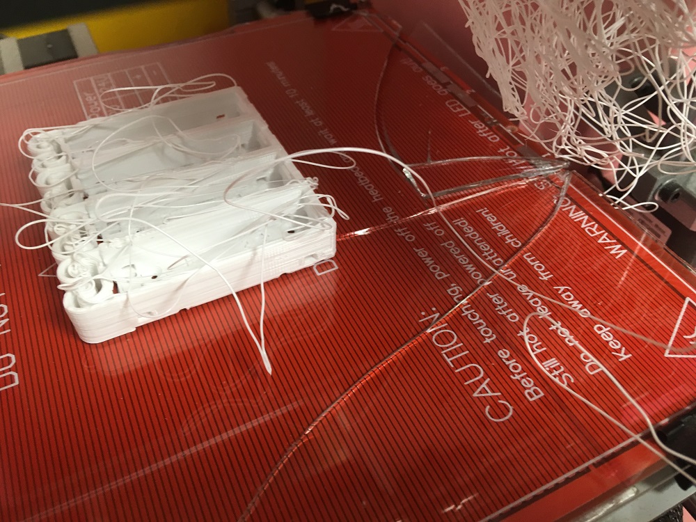
After letting the 3D printer run unattended, where it got lonely and rebelled...
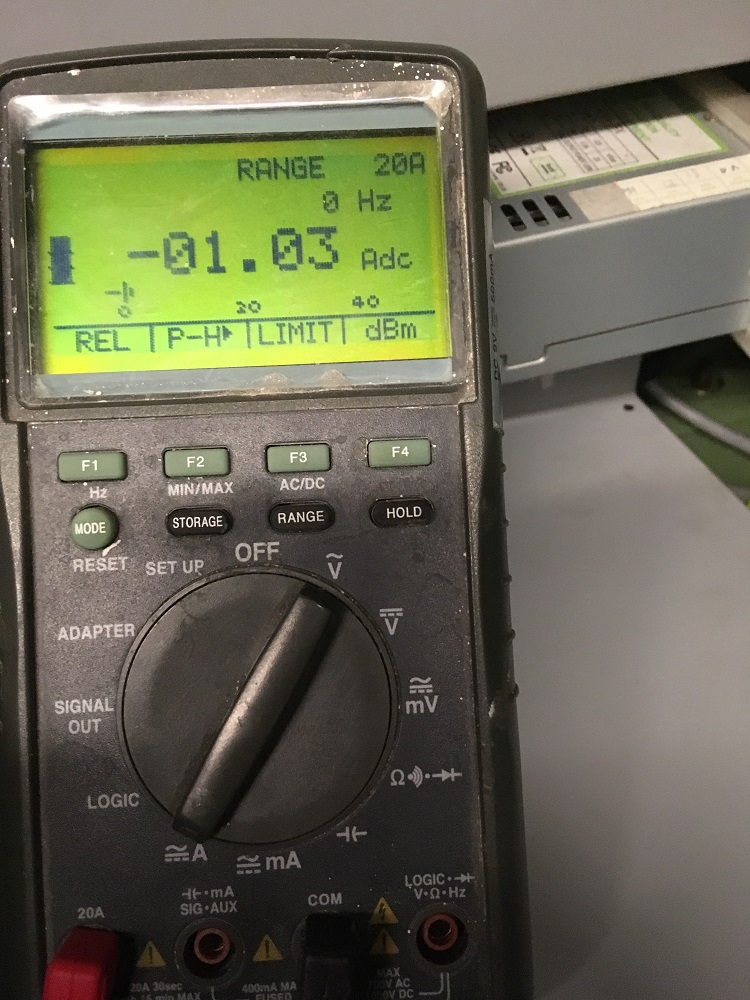
...finished wiring up the battery pack with 4x 2600mAh NiMH's. The are a few years old and only delivered 4.8V at idle, dropping to 3.8V powering the MAHO's 5V rail, measured at the exe. None of the exe's output a valid signal, and the MAHO E-stopped as soon as motion was commanded. If I need to move on to the EMI rabbit hole, I'll get some fresh batteries.
Switched out the battery pack for my hacked ATX PSU. It delivers 4.8V at idle, which is near the bottom of the Heidenhain spec. Once connected, X and Z were stable, and could be homed, but Y still E-stops as soon as motion is commanded.
The current draw of the whole 5V rail is 1.03A at start up. (Oops polarity reversed.)
Hanno, what sort of current rise would be expected in a failed capacitor case?
The next step will be to return the system to known start condition of using the chinese switching PSU, just to get Y working as before. For this the ammeter will be removed from the main rail supply point and wired to only measure the current to the Y EXE. Then run the circle drawing gcode, which draws one pattern, waits 15mins, draws the next , waits etc. And log the current flow during that test.
Then let it cool down again, and repeating the test for the 12V rail. This may be a likelier target If 5V supply to the 19A1 EXE is only passed through to power the encoder bulb, but the signal processing electronics are powered by the 12VDC.
Mark
There are a few different rabbit holes to explore:
- EMI from the 5V chinese
- EMI from the 12V ITX PSU
- Failing capacitors in the Y EXE channel
- ??? Floating single ended signals?
I'll try and work through them systematically. First up - the capacitors.
After letting the 3D printer run unattended, where it got lonely and rebelled...
...finished wiring up the battery pack with 4x 2600mAh NiMH's. The are a few years old and only delivered 4.8V at idle, dropping to 3.8V powering the MAHO's 5V rail, measured at the exe. None of the exe's output a valid signal, and the MAHO E-stopped as soon as motion was commanded. If I need to move on to the EMI rabbit hole, I'll get some fresh batteries.
Switched out the battery pack for my hacked ATX PSU. It delivers 4.8V at idle, which is near the bottom of the Heidenhain spec. Once connected, X and Z were stable, and could be homed, but Y still E-stops as soon as motion is commanded.
The current draw of the whole 5V rail is 1.03A at start up. (Oops polarity reversed.)
Hanno, what sort of current rise would be expected in a failed capacitor case?
The next step will be to return the system to known start condition of using the chinese switching PSU, just to get Y working as before. For this the ammeter will be removed from the main rail supply point and wired to only measure the current to the Y EXE. Then run the circle drawing gcode, which draws one pattern, waits 15mins, draws the next , waits etc. And log the current flow during that test.
Then let it cool down again, and repeating the test for the 12V rail. This may be a likelier target If 5V supply to the 19A1 EXE is only passed through to power the encoder bulb, but the signal processing electronics are powered by the 12VDC.
Mark
Attachments:
Last edit: 17 Jan 2019 08:20 by RotarySMP.
Please Log in or Create an account to join the conversation.
- RotarySMP
-
Topic Author
- Offline
- Platinum Member
-
Less
More
- Posts: 1627
- Thank you received: 595
17 Jan 2019 08:23 - 17 Jan 2019 08:25 #124335
by RotarySMP
Another procedure which is about 1000x easier with a four axis CNC machine.
Hanno, good choice on adding the 7i74. Much cleaner and easy hook up.
Mark
Replied by RotarySMP on topic Retrofitting a 1986 Maho MH400E
Here is something that can be done by using a slotting head.----
Internal Spiral Cutting www.practicalmachinist.com/vb/deckel-mah...iral-cutting-359503/
Bob
Another procedure which is about 1000x easier with a four axis CNC machine.
Hanno, good choice on adding the 7i74. Much cleaner and easy hook up.
Mark
Last edit: 17 Jan 2019 08:25 by RotarySMP.
Please Log in or Create an account to join the conversation.
- J Green
- Offline
- Elite Member
-
Less
More
- Posts: 164
- Thank you received: 24
17 Jan 2019 09:02 #124337
by J Green
Replied by J Green on topic Retrofitting a 1986 Maho MH400E
Mark
If you have another Meter , you can also measure the (AC scale on meter ) ripple value.. As in DC voltage ripple .
Although the meter may not be sensitive enough for high frequency .
isn't it HanMon ? my bifocals must be clouded - yup that's it !
Bob
If you have another Meter , you can also measure the (AC scale on meter ) ripple value.. As in DC voltage ripple .
Although the meter may not be sensitive enough for high frequency .
isn't it HanMon ? my bifocals must be clouded - yup that's it !
Bob
Please Log in or Create an account to join the conversation.
Moderators: piasdom
Time to create page: 0.243 seconds