converting a tos/intos fngj 40
- PCW
-

- Offline
- Moderator
-

Less
More
- Posts: 17624
- Thank you received: 5156
30 Oct 2024 16:56 #313498
by PCW
Replied by PCW on topic converting a tos/intos fngj 40
Do you have 5V and field power on the 7I77
(four yellow LEDs and one red LED illuminated on the 7I77)
Also posting your hal/ini files may help
(four yellow LEDs and one red LED illuminated on the 7I77)
Also posting your hal/ini files may help
Please Log in or Create an account to join the conversation.
- FPM
- Offline
- Junior Member
-

Less
More
- Posts: 24
- Thank you received: 0
06 Nov 2024 15:20 #313915
by FPM
Replied by FPM on topic converting a tos/intos fngj 40
looks like i haven't flashed the 7c81 correctly, now it seems to work.
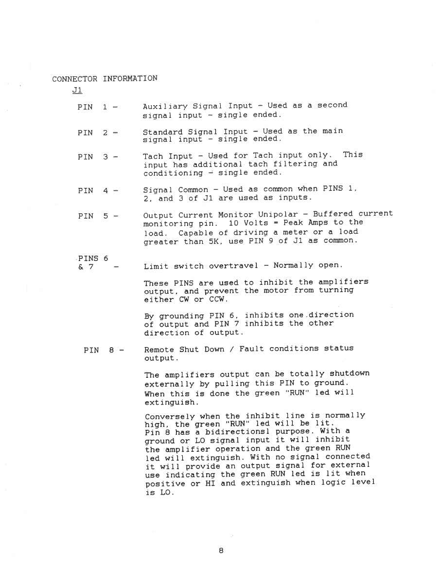
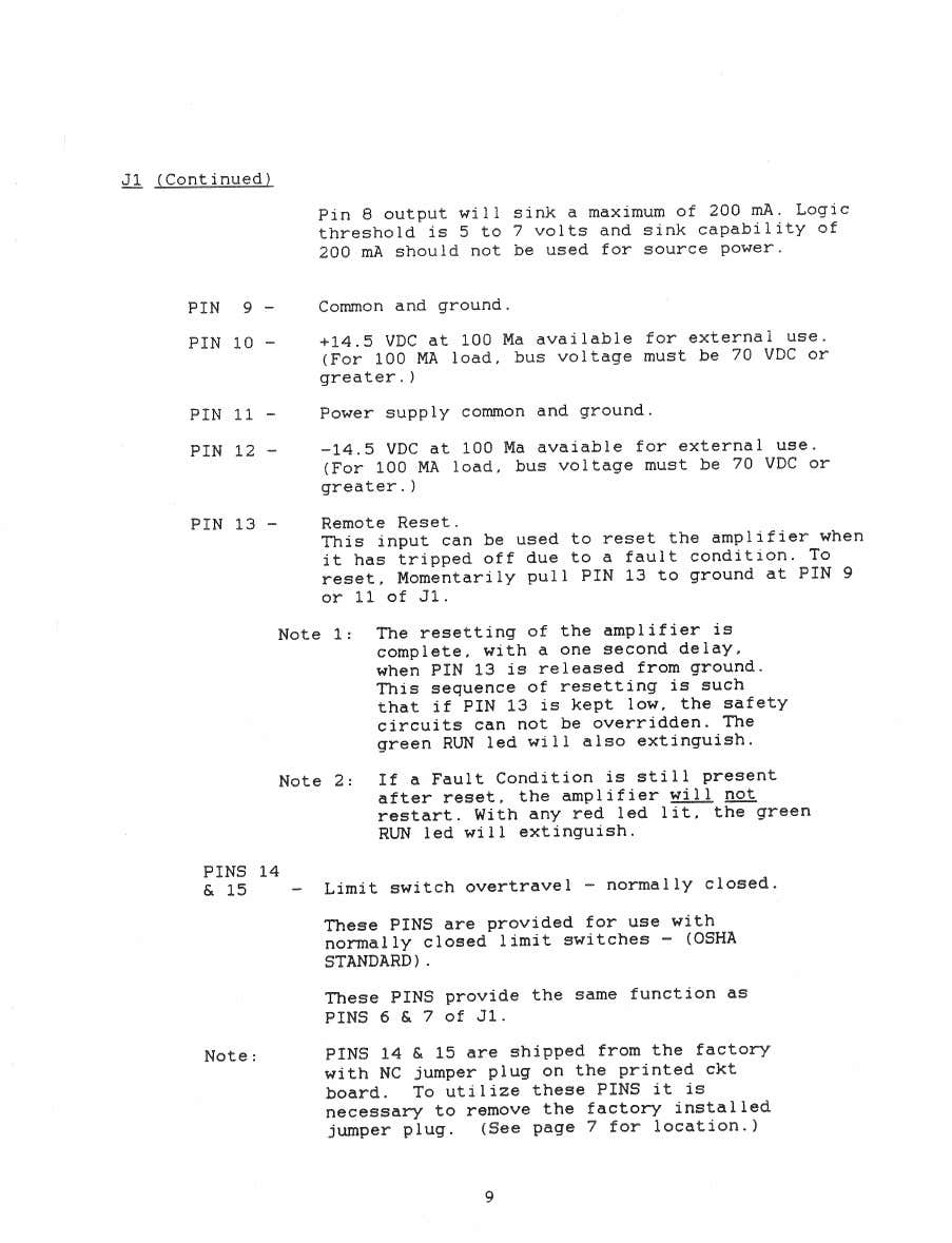
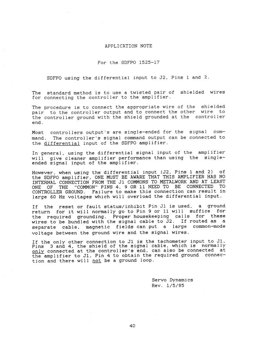
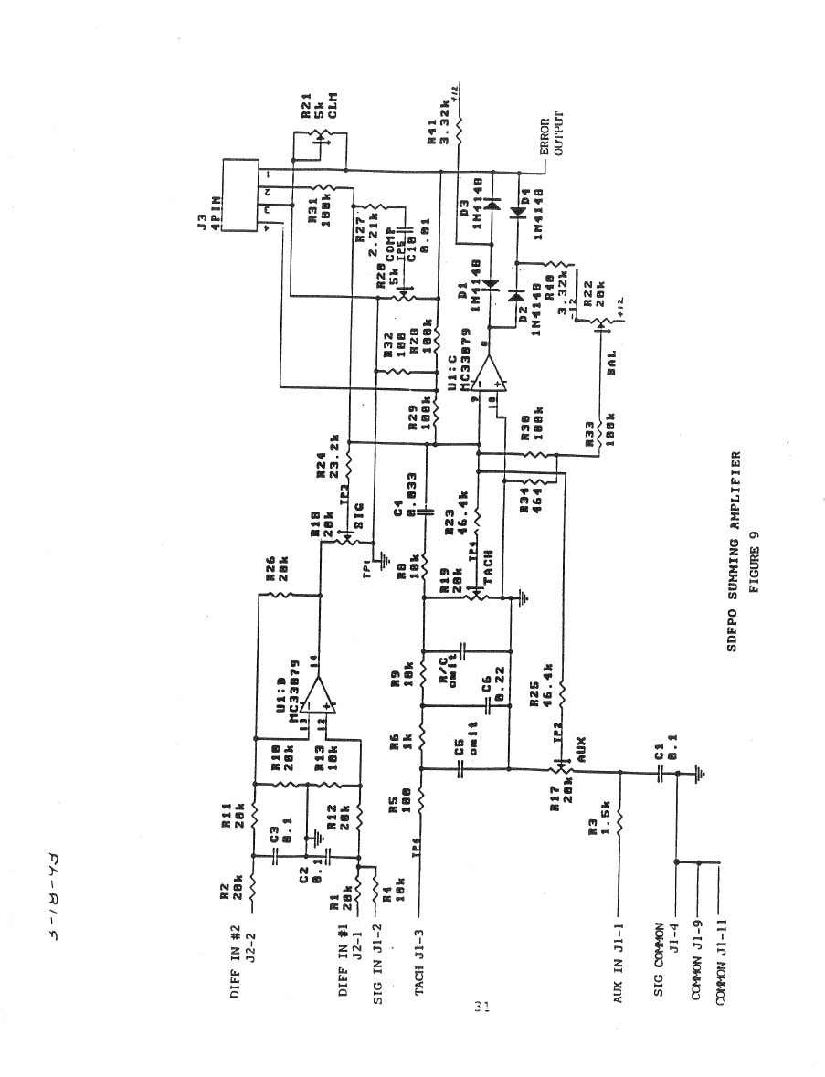
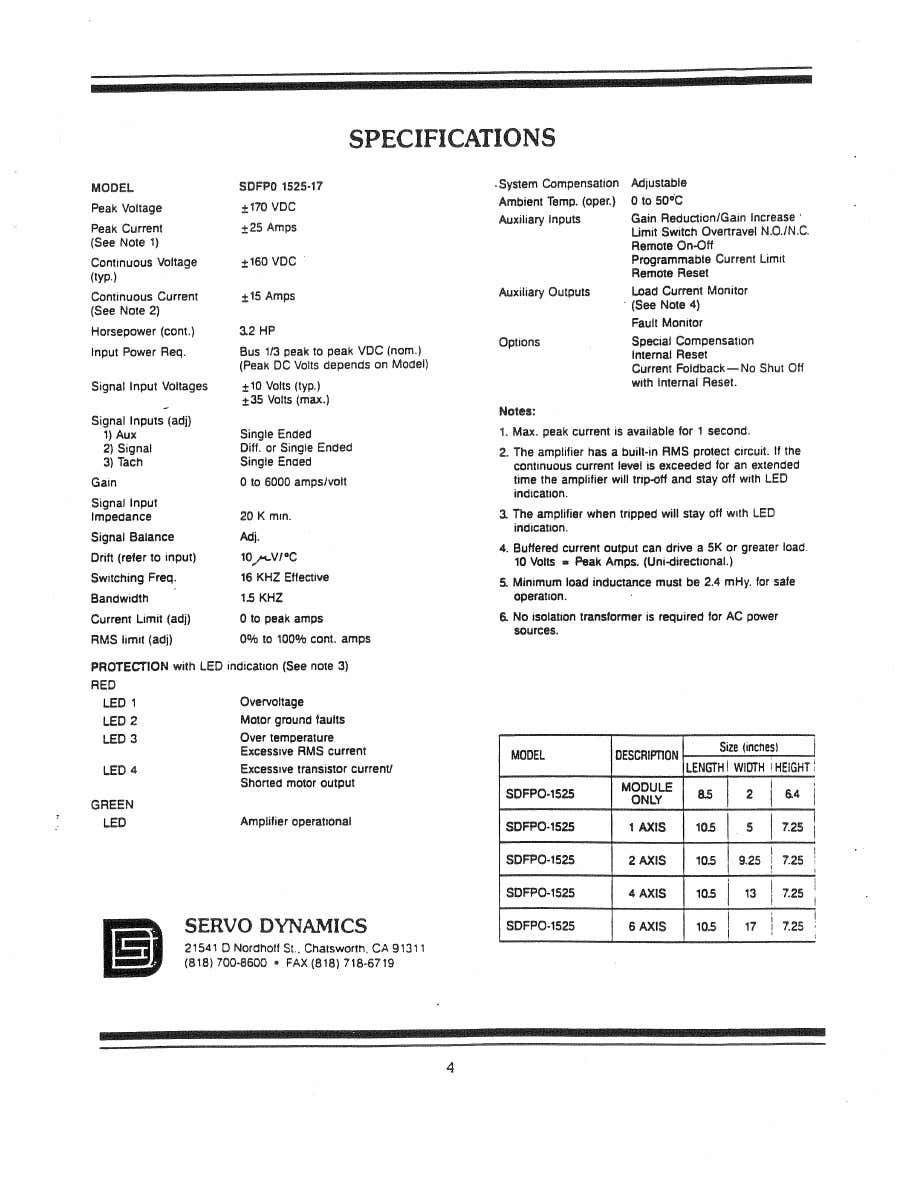
PCW suggested to connect the analog out and ground to the differential input J2 1,2. I have now found some interesting info online about the drive. I am interpreting this like that: i will connect the analog out to one of the diffential inputs and the ground to the Pin J1 4 or 9. Is this correct or should I connect the ground to the other diff input too?
PCW suggested to connect the analog out and ground to the differential input J2 1,2. I have now found some interesting info online about the drive. I am interpreting this like that: i will connect the analog out to one of the diffential inputs and the ground to the Pin J1 4 or 9. Is this correct or should I connect the ground to the other diff input too?
Attachments:
Please Log in or Create an account to join the conversation.
- PCW
-

- Offline
- Moderator
-

Less
More
- Posts: 17624
- Thank you received: 5156
06 Nov 2024 15:53 #313919
by PCW
Replied by PCW on topic converting a tos/intos fngj 40
7I77 AOUT --> Pin1 (IN+)
7I77 AGND --> Pin2 (IN-)
7I77 AGND --> Pin9 (common)
7I77 AGND --> Pin2 (IN-)
7I77 AGND --> Pin9 (common)
The following user(s) said Thank You: FPM
Please Log in or Create an account to join the conversation.
- FPM
- Offline
- Junior Member
-

Less
More
- Posts: 24
- Thank you received: 0
06 Nov 2024 16:16 - 06 Nov 2024 16:19 #313923
by FPM
Replied by FPM on topic converting a tos/intos fngj 40
In the Ini File I have set the encoder scale, they seem to work correctly. But I can't figure out where i need to set the ratio to the motor (for example 5mm Ballscrew+ 1to2 belt). The manual specifies it for steppers, but not for servos
, OUTPUT_SCALE seems to be something different. I seems logical that a current mode amp setup does not need it but I don't know.
Last edit: 06 Nov 2024 16:19 by FPM.
Please Log in or Create an account to join the conversation.
- PCW
-

- Offline
- Moderator
-

Less
More
- Posts: 17624
- Thank you received: 5156
06 Nov 2024 17:04 - 06 Nov 2024 17:38 #313926
by PCW
Replied by PCW on topic converting a tos/intos fngj 40
if that's a 2 to 1 encoder to ballscrew ratio. the encoder scale would be
encoder counts/turn * 2 / 5
where encoder counts are PPR*4
If these are torque mode drives (no tachometer feedback) the output scale can be left as-is
if these are velocity mode drives with tachometer feedback, it's helpful to set the OUTPUT_SCALE
to mm/s at 10V (full scale) so the PID values are normalized (and FF1 is 1.0)
Last edit: 06 Nov 2024 17:38 by PCW.
Please Log in or Create an account to join the conversation.
- FPM
- Offline
- Junior Member
-

Less
More
- Posts: 24
- Thank you received: 0
06 Nov 2024 17:26 #313928
by FPM
Replied by FPM on topic converting a tos/intos fngj 40
Please Log in or Create an account to join the conversation.
- PCW
-

- Offline
- Moderator
-

Less
More
- Posts: 17624
- Thank you received: 5156
06 Nov 2024 17:39 #313930
by PCW
Replied by PCW on topic converting a tos/intos fngj 40
If they have tachometer feedback, they are velocity mode drives.
(a velocity mode drive is a torque mode drive with local velocity feedback)
(a velocity mode drive is a torque mode drive with local velocity feedback)
Please Log in or Create an account to join the conversation.
- FPM
- Offline
- Junior Member
-

Less
More
- Posts: 24
- Thank you received: 0
06 Nov 2024 19:12 #313937
by FPM
Replied by FPM on topic converting a tos/intos fngj 40
Thank you very much PCW, you are helping me a lot with this project.
Ok, so if I understood this correctly, to calculate the output_scale, I need the rpm the motor makes at 10V input signal and from that calculate the linear velocity, but since i cant find anything like that in the specs, I guess i need to measure it?
Ok, so if I understood this correctly, to calculate the output_scale, I need the rpm the motor makes at 10V input signal and from that calculate the linear velocity, but since i cant find anything like that in the specs, I guess i need to measure it?
Please Log in or Create an account to join the conversation.
- PCW
-

- Offline
- Moderator
-

Less
More
- Posts: 17624
- Thank you received: 5156
06 Nov 2024 20:23 - 06 Nov 2024 20:25 #313951
by PCW
Replied by PCW on topic converting a tos/intos fngj 40
Its not the RPM you need but rather the linear mm/s velocity at 10V
If you have your encoder scale set correctly (check first) you can
measure this at the encoder velocity pin (it should read in mm/s
if scaled properly)
Edit, I miss-understood, yes, measuring the RPM if you have a way
to do this without LinuxCNC should work as well
If you have your encoder scale set correctly (check first) you can
measure this at the encoder velocity pin (it should read in mm/s
if scaled properly)
Edit, I miss-understood, yes, measuring the RPM if you have a way
to do this without LinuxCNC should work as well
Last edit: 06 Nov 2024 20:25 by PCW.
Please Log in or Create an account to join the conversation.
- FPM
- Offline
- Junior Member
-

Less
More
- Posts: 24
- Thank you received: 0
23 Nov 2024 13:27 #315102
by FPM
Replied by FPM on topic converting a tos/intos fngj 40
Pin8 of the servo driver is like written in pinout a inhibit pin. So this should be connected to the mesa enable+ pin and enable- pin to GND. The Manual i ve attached says Pin 8 can sink about 200mA but this has nothing to do with how much it draws. So the 50mA of the enable switch should be fine right?
Please Log in or Create an account to join the conversation.
Moderators: piasdom
Time to create page: 0.233 seconds

