Splines to Gcode from dxf file
- jtc
-
 Topic Author
- Offline
- Premium Member
-

Less
More
- Posts: 147
- Thank you received: 12
06 Sep 2016 22:15 #80098
by jtc
Splines to Gcode from dxf file was created by jtc
Hi!
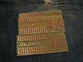
I'm working on a small program that reads from a dxf file the points of splines. At the moment and debugging the data read from the file I got control points and fit points
The main goal is to convert in Gcode to use with a plasma cnc. For what I have seen on the documentation (linuxcnc.org/docs/html/gcode/g-code.html#gcode:g5) there are cubic splines, quadratic splines and the nurbs block.
So, what is the best way to do this? the typical order of the spline in the cad program is 3(cubic splines). Its better practice use G5, or can I obtain the same results with G5.2/G5.3?
Note that I can be able to start cut from the end beginning of the curve, but so also from the end in reverse direction, if one of the Gcodes eases this process it must be considerate.
João
Please Log in or Create an account to join the conversation.
- andypugh
-

- Offline
- Moderator
-

Less
More
- Posts: 19879
- Thank you received: 4642
07 Sep 2016 20:07 #80165
by andypugh
Replied by andypugh on topic Splines to Gcode from dxf file
I have no idea, but I wold love to hear what you learn in the process. I got completely baffled trying to convert CAD data in Inventor into SVG Beziers. forums.autodesk.com/t5/inventor-customiz...ighlight/true#M54006
Please Log in or Create an account to join the conversation.
- jtc
-
Topic Author
- Offline
- Premium Member
-
Less
More
- Posts: 147
- Thank you received: 12
07 Sep 2016 21:16 #80182
by jtc
I don't have any experience with svg files, only read and write dxf files.
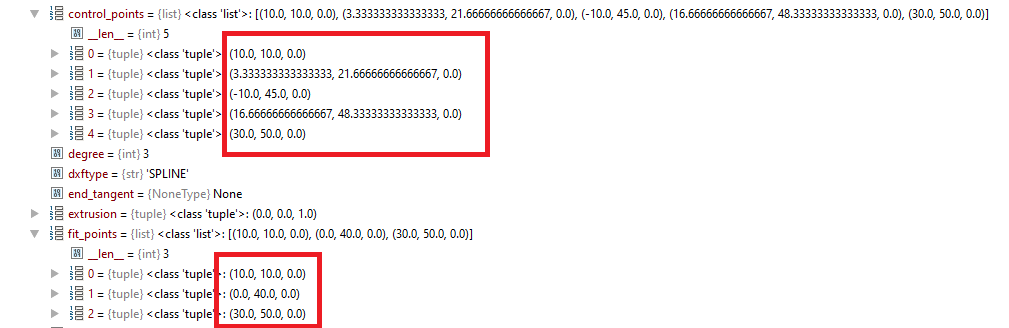
today I made some work, this is the first implementation with g5.2 /g5.3
the basic is working, but the splines looks different from the drawing. now its a question of understanding the L and P parameters to adjust it correctly. After this is reversing the path.
João
Replied by jtc on topic Splines to Gcode from dxf file
I have no idea, but I wold love to hear what you learn in the process. I got completely baffled trying to convert CAD data in Inventor into SVG Beziers. forums.autodesk.com/t5/inventor-customiz...ighlight/true#M54006
I don't have any experience with svg files, only read and write dxf files.
today I made some work, this is the first implementation with g5.2 /g5.3
the basic is working, but the splines looks different from the drawing. now its a question of understanding the L and P parameters to adjust it correctly. After this is reversing the path.
João
Please Log in or Create an account to join the conversation.
- Matt Hat
- Offline
- Senior Member
-

Less
More
- Posts: 47
- Thank you received: 2
26 Dec 2021 22:30 - 26 Dec 2021 23:07 #230031
by Matt Hat
Replied by Matt Hat on topic Splines to Gcode from dxf file
I would be interested in a rigorous definition of the parameters used in G5, namely what exactly is the definition of I, J, P, and Q ?
linuxcnc.org/docs/html/gcode/g-code.html#gcode:g5
The missing link: conversion of cubic polynomial coefficients to I,J,P, and Q.
The 3rd order (cubic) splines are simply defined by four polynomial coefficients. Start and end points (also called nodes) will give two constraints, two more follow from the continuity of the first and second derivatives.
My favorite tools for post-processing are GNU octave and Python. Fit of cubic splines to any curve shape is quite simple using e.g. the splinefit command within octave. So far so good.
I am uncertain how to translate the polynomial coefficients to control points required for a B-spline definition. By some method, the correct control points have to be found - as referred to in G5 commands by i,J, P and Q I assume.
Graphically speaking, this would required to draw the outside polygon for a given curve. Geometrically speaking, we have to draw tangents to all knots and intersect two subsequent tangents to obtain the control points.
Conclusively,
I am looking for a simple implementation to calculate the control points of a B-spline for a given cubic (polynomial) spline. This would allow me to mill along piecewise cubic spline trajectories using G5 command.
Any experiences or suggestions to share?
Last edit: 26 Dec 2021 23:07 by Matt Hat. Reason: formating
Please Log in or Create an account to join the conversation.
- Grotius
-

- Offline
- Platinum Member
-

Less
More
- Posts: 2419
- Thank you received: 2348
27 Dec 2021 00:10 - 27 Dec 2021 00:24 #230036
by Grotius
Replied by Grotius on topic Splines to Gcode from dxf file
Hi,
I often imported dxf splines and passed them into lcnc gcode.
It can be hard to get the splines look the same in different programs. I think different algo's are used.
It's a shame the acad algo is closed source. In this way you can never replicate the spline. Autodesk f.ckers.
Splines using fitpoints are my favorite.
On my github there are different spline library's. Also a 3d spline with fitpoints is over there. And a 2d spline algo made
by a mathician for me.
Programs like inkscape exports a spline to a linestrip. This is a option. A more exotic option is to
export a spline into arc segments.
This is from the dxfrw lib, the same as Freecad and others are using, line 847 to 900 gives dxf spline info.
I use this lib for importing dxf and then parse to gcode. See "big data" attachement.

github release page: halcore/src/hal/components/matrix/cpp_interface/libspline => bezier_spline, cubic_spline, spline
github release page: halcore/src/hal/components/matrix/cpp_interface/libdxfrw => dxfrw lib
Not really good, but for info:
read spline: github.com/grotius-cnc/qt_cadcam_rev/blo...xf/dxf_read_spline.h
draw spline: github.com/grotius-cnc/qt_cadcam_rev/blo...er/display/display.h
Implementation of 3d splinelib, very cool:
github.com/grotius-cnc/splinelib
2d spline algo using fitpoints starting at line 185
github.com/grotius-cnc/cadcam/blob/master/opengl.cpp
I often imported dxf splines and passed them into lcnc gcode.
It can be hard to get the splines look the same in different programs. I think different algo's are used.
It's a shame the acad algo is closed source. In this way you can never replicate the spline. Autodesk f.ckers.
Splines using fitpoints are my favorite.
On my github there are different spline library's. Also a 3d spline with fitpoints is over there. And a 2d spline algo made
by a mathician for me.
Programs like inkscape exports a spline to a linestrip. This is a option. A more exotic option is to
export a spline into arc segments.
This is from the dxfrw lib, the same as Freecad and others are using, line 847 to 900 gives dxf spline info.
I use this lib for importing dxf and then parse to gcode. See "big data" attachement.
github release page: halcore/src/hal/components/matrix/cpp_interface/libspline => bezier_spline, cubic_spline, spline
github release page: halcore/src/hal/components/matrix/cpp_interface/libdxfrw => dxfrw lib
Not really good, but for info:
read spline: github.com/grotius-cnc/qt_cadcam_rev/blo...xf/dxf_read_spline.h
draw spline: github.com/grotius-cnc/qt_cadcam_rev/blo...er/display/display.h
Implementation of 3d splinelib, very cool:
github.com/grotius-cnc/splinelib
2d spline algo using fitpoints starting at line 185
github.com/grotius-cnc/cadcam/blob/master/opengl.cpp
Last edit: 27 Dec 2021 00:24 by Grotius.
The following user(s) said Thank You: jtc, Matt Hat
Please Log in or Create an account to join the conversation.
- Matt Hat
- Offline
- Senior Member
-
Less
More
- Posts: 47
- Thank you received: 2
27 Dec 2021 08:31 #230050
by Matt Hat
Replied by Matt Hat on topic Splines to Gcode from dxf file
Great, many thanks. I will look into these resources and hopefully contribute with some transportation to octave of py. They just run so smooth beside any linuxcnc installation. Anything that is free from commercial interests is fine. ")
Please Log in or Create an account to join the conversation.
- Matt Hat
- Offline
- Senior Member
-
Less
More
- Posts: 47
- Thank you received: 2
29 Dec 2021 12:00 - 29 Dec 2021 12:04 #230213
by Matt Hat
Replied by Matt Hat on topic Splines to Gcode from dxf file
What is the linuxcnc interpretation of G5 G5.1 and G5.2 ?
Can I access that source code? Is there a more detailed documentation?
I had luckily some time to do a little math on splines and geometrical shape approximation. However, I still miss to translate a given spline to B-Splines or even NURBS. Unfortunately, linuxcnc does not seem to support simple splines. I am still glad it supports other splines though.
If a CAD-CAM or post-processor already outputs B-Spline or NURBS, it should be simpler to convert to G-Command. Probably a translation from global to relative coordinates should do it to specify the positions of the control points relative to the way points.
Interpolation of a spline - as any graphics program does it to actually plot the spline - is relatively simple. Tricky is the conversion between different types of splines, and in particular, convert it to the format linuxcnc is accepting.
A curious property of splines is, that boundary conditions will affect the shape of the spline globally. A wrong conversion of the boundary conditions will change the shape of the whole spline. I think this is the reason why João gets splines looking different than expected.
A common approach to relax the dependency of the shape on the boundary conditions, is to add more or multiple points (also called knots, nodes, or tool way points) at the two ends of the spline. Either more dense points or additional virtual points that are only used for computation but finally dropped in any output.
Whatever is automatically added and dropped, will not be accessible. Likely a good reason for any CAD-CAM or post-processor to simply output a sequence of unique short straight line segments instead.
I guess we need to pass the control points to a G5 commands relatively to the knots. Challenging is the reconstruction of the control points (also called control polygon) for a given spline. Unfortunately, fitting of B-Splines or NURBS to a given discrete set of way points is far more tricky than fitting of a simple cubic pp spline. I did not find support of B-Spline fitting in GNU octave and Matlab has hidden that function in an exotic 'robotic systems' toolbox; it is not even in the 'curve fitting' toolbox as all the other spline functionalities.
Good news is: the control points of a given pp spline can be reconstructed by solving a conventional set of linear equations. This way a pp spline could be transformed to a B-Spline: Calculate first the control points and construct from these the B-Spline or NURBS. Algorithms for solving the set of linear equations can be found and likely adapted. The missing link, again, is the proper definition of the boundary conditions.
Any advice on how to fix the boundary conditions programmatically is heartily welcome. Padding with additional points outside the planned tool trace is not much helpful. These points will not be milled and should not appear in any G-Code. A higher density of points is also not much interesting, I rather go with straight segments then")
I did upload my GNU Octave and Matlab scrips to: github.com/Matttab/spline-examples
Use of simple polynominal and B-Splines in GNU Octave and Matlab for geometrical shape approximation
The objective are simple spline approximations of common geometric shapes with potential practical use in CNC machining. Interest is on spline interpolations with a low number of parameters, describing common shapes such as circles, ellipses, squares, slots, pockets and contours of arbitrary shape. Splines are used in the CAD to define the geometry, in the CAM to define the tool path by a list of dedicated G-code machine instructions, and in the CNC control SW, to eventually interpolate G5 spline instruction to actual workpiece or tool movements. Mapping of spline parameters to dimensions of the geometrical entities is welcome. Conversion of parameters between different types of splines is part of adaption to the broad variety of commercial and home-made hobbyist CAD-CAM-CNC systems.
Can I access that source code? Is there a more detailed documentation?
I had luckily some time to do a little math on splines and geometrical shape approximation. However, I still miss to translate a given spline to B-Splines or even NURBS. Unfortunately, linuxcnc does not seem to support simple splines. I am still glad it supports other splines though.
If a CAD-CAM or post-processor already outputs B-Spline or NURBS, it should be simpler to convert to G-Command. Probably a translation from global to relative coordinates should do it to specify the positions of the control points relative to the way points.
Interpolation of a spline - as any graphics program does it to actually plot the spline - is relatively simple. Tricky is the conversion between different types of splines, and in particular, convert it to the format linuxcnc is accepting.
A curious property of splines is, that boundary conditions will affect the shape of the spline globally. A wrong conversion of the boundary conditions will change the shape of the whole spline. I think this is the reason why João gets splines looking different than expected.
A common approach to relax the dependency of the shape on the boundary conditions, is to add more or multiple points (also called knots, nodes, or tool way points) at the two ends of the spline. Either more dense points or additional virtual points that are only used for computation but finally dropped in any output.
Whatever is automatically added and dropped, will not be accessible. Likely a good reason for any CAD-CAM or post-processor to simply output a sequence of unique short straight line segments instead.
I guess we need to pass the control points to a G5 commands relatively to the knots. Challenging is the reconstruction of the control points (also called control polygon) for a given spline. Unfortunately, fitting of B-Splines or NURBS to a given discrete set of way points is far more tricky than fitting of a simple cubic pp spline. I did not find support of B-Spline fitting in GNU octave and Matlab has hidden that function in an exotic 'robotic systems' toolbox; it is not even in the 'curve fitting' toolbox as all the other spline functionalities.
Good news is: the control points of a given pp spline can be reconstructed by solving a conventional set of linear equations. This way a pp spline could be transformed to a B-Spline: Calculate first the control points and construct from these the B-Spline or NURBS. Algorithms for solving the set of linear equations can be found and likely adapted. The missing link, again, is the proper definition of the boundary conditions.
Any advice on how to fix the boundary conditions programmatically is heartily welcome. Padding with additional points outside the planned tool trace is not much helpful. These points will not be milled and should not appear in any G-Code. A higher density of points is also not much interesting, I rather go with straight segments then
I did upload my GNU Octave and Matlab scrips to: github.com/Matttab/spline-examples
Use of simple polynominal and B-Splines in GNU Octave and Matlab for geometrical shape approximation
The objective are simple spline approximations of common geometric shapes with potential practical use in CNC machining. Interest is on spline interpolations with a low number of parameters, describing common shapes such as circles, ellipses, squares, slots, pockets and contours of arbitrary shape. Splines are used in the CAD to define the geometry, in the CAM to define the tool path by a list of dedicated G-code machine instructions, and in the CNC control SW, to eventually interpolate G5 spline instruction to actual workpiece or tool movements. Mapping of spline parameters to dimensions of the geometrical entities is welcome. Conversion of parameters between different types of splines is part of adaption to the broad variety of commercial and home-made hobbyist CAD-CAM-CNC systems.
Last edit: 29 Dec 2021 12:04 by Matt Hat.
Please Log in or Create an account to join the conversation.
- Grotius
-
- Offline
- Platinum Member
-
Less
More
- Posts: 2419
- Thank you received: 2348
29 Dec 2021 12:16 #230218
by Grotius
Replied by Grotius on topic Splines to Gcode from dxf file
Hi,
What is the linuxcnc interpretation of G5 G5.1 and G5.2 ?
Can I access that source code? Is there a more detailed documentation?
There is a source code for it indeed, that shows how it's been calculated.
some source code
starting at line 188.
The spline algo starting at line 212.
P.s the github link doen't work.
It think now you can test some more !
Please Log in or Create an account to join the conversation.
- Matt Hat
- Offline
- Senior Member
-
Less
More
- Posts: 47
- Thank you received: 2
29 Dec 2021 14:18 - 29 Dec 2021 14:28 #230240
by Matt Hat
Replied by Matt Hat on topic Splines to Gcode from dxf file
I switched the github repo from private to public this morning. I hope it works by now, else let me know.
Yes, that code fragments help a lot to stitch things together.
Yes, that code fragments help a lot to stitch things together.
Last edit: 29 Dec 2021 14:28 by Matt Hat.
Please Log in or Create an account to join the conversation.
- Grotius
-
- Offline
- Platinum Member
-
Less
More
- Posts: 2419
- Thank you received: 2348
29 Dec 2021 17:21 #230259
by Grotius
Replied by Grotius on topic Splines to Gcode from dxf file
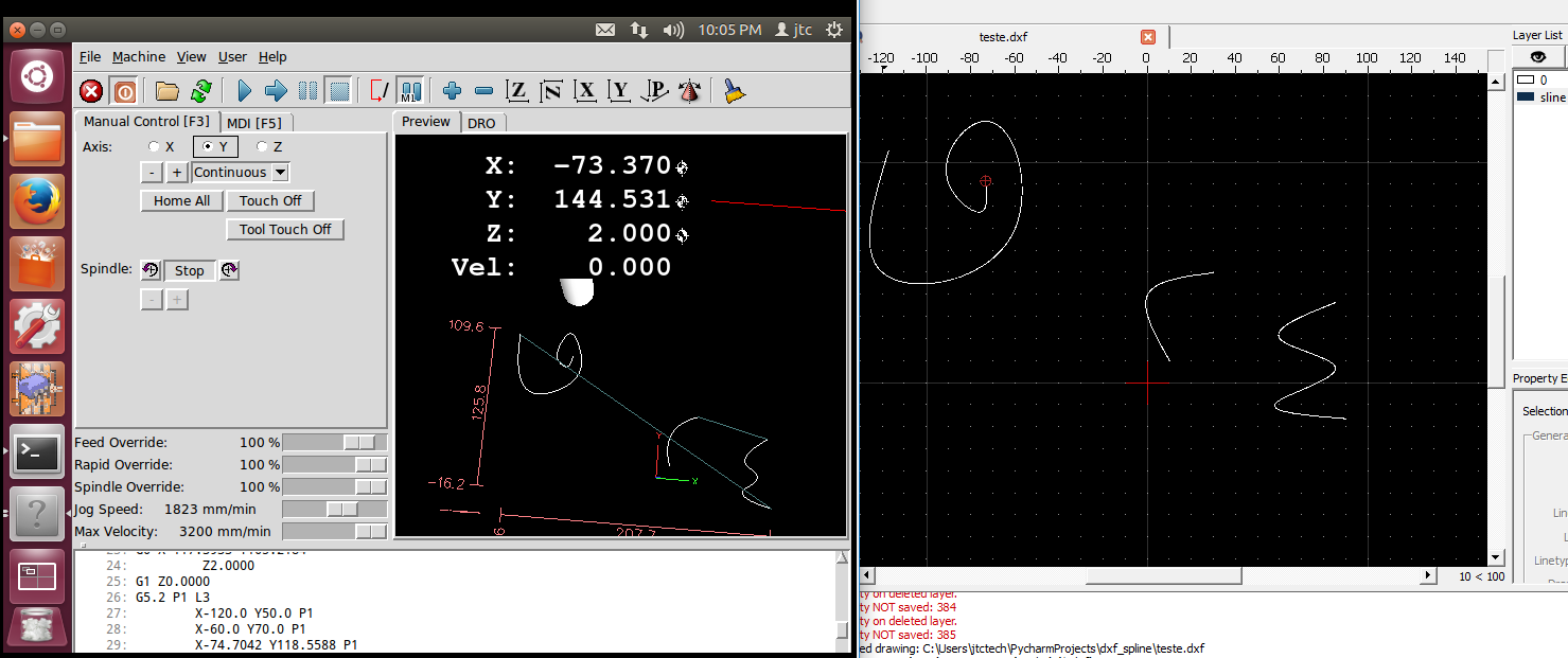
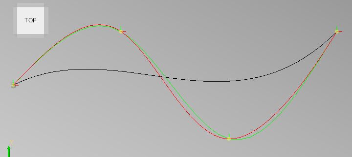
Hi, i just did a short test:
Black is the lcnc spline algo.
Red is the cubic spline algo.
Green is the 3d spline algo.
It looks like the lcnc spline is not really a spline.
void SPLINE_FEED(double x1, double y1, double x2, double y2, double x3, double y3) {
    double x0 = 0;
    double y0 = 0;
    pvec_v.push_back({0,0,0});

    for(int i=1; i<=100; i++) {      double t = i / 100.;
        double t3 = t*t*t;
        double t2 = 3*t*t*(1-t);
        double t1 = 3*t*(1-t)*(1-t);
        double t0 = (1-t)*(1-t)*(1-t);
        double x = x0*t0 + x1*t1 + x2*t2 + x3*t3;
        double y = y0*t0 + y1*t1 + y2*t2 + y3*t3;
        double z = 0;

        pvec_v.push_back({x,y,z});
    }
}

void cubic_spline(){

    std::vector<std::vector<double>> C; //2d array
    C.push_back({0,0});
    C.push_back({100,50});
    C.push_back({200,-50});
    C.push_back({300,50});

    double S[C.size()-1][2][4];
    double w, b[C.size()], d[C.size()], x[C.size()];
    int i, dim;
    int n = C.size()-1; // number of splines

    for(dim=0; dim<2; dim++)
    {
        // define d[]:
        d[0]=3.0*(C[1][dim]-C[0][dim]);
        for(i=1; i<n; i++)
            d[i]=3.0*(C[i+1][dim]-C[i-1][dim]);
        d[n]=3.0*(C[n][dim]-C[n-1][dim]);
        // forward sweep: (simplified tridiagonal solution: all a[i]=1 and all c[i]=1)
        b[0]=2.0;
        for(i=1; i<C.size(); i++)
        {
            w = 1.0/b[i-1];
            b[i] = 4.0 - w;
            d[i] -= (w*d[i-1]);
        }
        // calculate solution vector x[i] = D[i]:
        // (Wikipedia x[] = Wolfram D[])
        x[n]=d[n]/b[n];
        for(i=n-1; i>=0; i--)
            x[i]=(d[i]-x[i+1])/b[i];
        // calculate spline S[i][dim] a, b, c and d:
        for(i=0; i<n; i++)
        {
            S[i][dim][0]=C[i][dim];
            S[i][dim][1]=x[i];
            S[i][dim][2]=3.0*(C[i+1][dim]-C[i][dim]) - 2.0*x[i] - x[i+1];
            S[i][dim][3]=2.0*(C[i][dim]-C[i+1][dim]) + x[i] + x[i+1];
        }
    }

    for(int p=0; p<C.size()-1; p++)  //spline points
    {
        for(double t=0; t<1; t+=0.01)  //time 0-1 for each spline
        {
            double px = ((S[p][0][3]*t+S[p][0][2])*t+S[p][0][1])*t+S[p][0][0];
            double py = ((S[p][1][3]*t+S[p][1][2])*t+S[p][1][1])*t+S[p][1][0];
            //std::cout<< "x:" << px << " y:" << py << std::endl;
            pvec_a.push_back({px,py,0});
        }
    }

}

void MainWindow::on_pushButton_pressed()
{
    //!
    Handle(AIS_Shape) ashape=draw_primitives().draw_3d_origin({0,0,0},5);
    OpencascadeWidget->show_shape(ashape);
    ashape=draw_primitives().draw_3d_origin({100,50,0},5);
    OpencascadeWidget->show_shape(ashape);
    ashape=draw_primitives().draw_3d_origin({200,-50,0},5);
    OpencascadeWidget->show_shape(ashape);
     ashape=draw_primitives().draw_3d_origin({300,50,0},5);
    OpencascadeWidget->show_shape(ashape);
    OpencascadeWidget->Redraw();

    SPLINE_FEED(100,50,200,-50,300,50);

    cubic_spline(); //black

    gp_Pnt p;
    std::vector<gp_Pnt> pvec;
    p.SetXYZ({0,0,0});
    pvec.push_back(p);
    p.SetXYZ({100,50,0});
    pvec.push_back(p);
    p.SetXYZ({200,-50,0});
    pvec.push_back(p);
    p.SetXYZ({300,50,0});
    pvec.push_back(p);
    ashape=draw_primitives().draw_3d_spline(pvec,10);
    OpencascadeWidget->show_shape(ashape);
    ashape=draw_primitives().colorize(ashape,Quantity_NOC_GREEN,0); //green
    OpencascadeWidget->Redraw();

    draw_result();
}
Black is the lcnc spline algo.
Red is the cubic spline algo.
Green is the 3d spline algo.
It looks like the lcnc spline is not really a spline.
Attachments:
Please Log in or Create an account to join the conversation.
Time to create page: 0.204 seconds