Splines to Gcode from dxf file
- andypugh
-

- Offline
- Moderator
-

Less
More
- Posts: 19861
- Thank you received: 4636
29 Dec 2021 20:02 #230272
by andypugh
Replied by andypugh on topic Splines to Gcode from dxf file
The G5 splines were a bit of a push-and-run rather a long time ago. I have a feeling that they were a masters project and then the author moved on.
I am not sure that the link above (to gcodemodule.cc) is the best place to look. You should probably look in interp_convert:
github.com/LinuxCNC/linuxcnc/blob/3cef75...terp_convert.cc#L123
It seems that an academic paper resulted: www.unipa.it/persone/docenti/l/ernesto.l...Pubblicazione=141770
I am not sure that the link above (to gcodemodule.cc) is the best place to look. You should probably look in interp_convert:
github.com/LinuxCNC/linuxcnc/blob/3cef75...terp_convert.cc#L123
It seems that an academic paper resulted: www.unipa.it/persone/docenti/l/ernesto.l...Pubblicazione=141770
Please Log in or Create an account to join the conversation.
- Grotius
-

- Offline
- Platinum Member
-

Less
More
- Posts: 2419
- Thank you received: 2348
29 Dec 2021 22:05 #230285
by Grotius
Replied by Grotius on topic Splines to Gcode from dxf file
Hi,
The G5 splines were a bit of a push-and-run rather a long time ago. I have a feeling that they were a masters project and then the author moved on.
Ok. Nice to know.
linuxcnc spline algo found in this document page 24
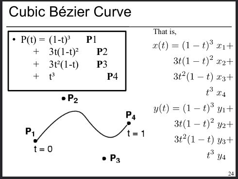
It's a cubic bezier curve.... Not even a spline.
The G5 splines were a bit of a push-and-run rather a long time ago. I have a feeling that they were a masters project and then the author moved on.
Ok. Nice to know.
linuxcnc spline algo found in this document page 24
It's a cubic bezier curve.... Not even a spline.
Attachments:
The following user(s) said Thank You: jtc
Please Log in or Create an account to join the conversation.
- Grotius
-
- Offline
- Platinum Member
-
Less
More
- Posts: 2419
- Thank you received: 2348
29 Dec 2021 22:29 #230287
by Grotius
Replied by Grotius on topic Splines to Gcode from dxf file
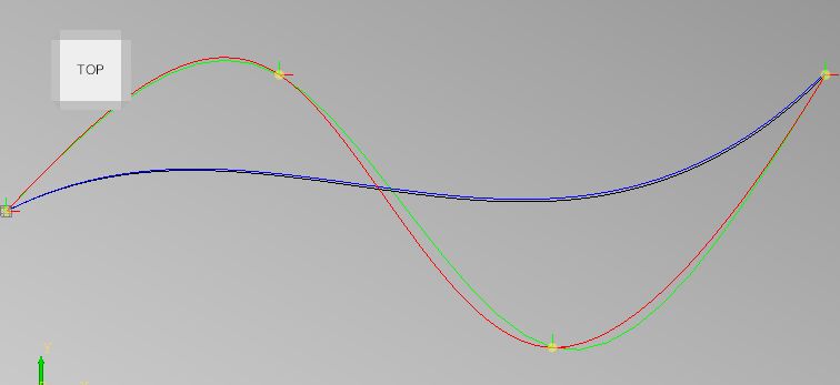
The testcase :
Result :
I gave them a offset of 1mm in y to show them both.
void SPLINE_FEED(double x1, double y1, double x2, double y2, double x3, double y3) {
    double x0 = 0;
    double y0 = 0;
    pvec_v.push_back({0,0,0});

    for(int i=1; i<=100; i++) {      double t = i / 100.;

        double t3 = t*t*t;
        double t2 = 3*t*t*(1-t);
        double t1 = 3*t*(1-t)*(1-t);
        double t0 = (1-t)*(1-t)*(1-t);
        double x = x0*t0 + x1*t1 + x2*t2 + x3*t3;
        double y = y0*t0 + y1*t1 + y2*t2 + y3*t3;
        double z = 0;

        pvec_v.push_back({x,y,z});  //black
    }
}

void cubic_bezier_curve(double x1, double y1, double x2, double y2, double x3, double y3){

    double x0 = 0;
    double y0 = 0;
    pvec_s.push_back({0,0,0});

    for(int i=1; i<=100; i++) {      double t = i / 100.;
        double x=pow((1-t),3)*x0 + 3*t*pow((1-t),2)*x1 + 3* t*t *(1-t)*x2 + t*t*t*x3;
        double y=pow((1-t),3)*y0 + 3*t*pow((1-t),2)*y1 + 3* t*t *(1-t)*y2 + t*t*t*y3;
        double z = 0;

        pvec_s.push_back({x,y,z}); //blue
    }
}
Result :
I gave them a offset of 1mm in y to show them both.
Attachments:
Please Log in or Create an account to join the conversation.
- Grotius
-
- Offline
- Platinum Member
-
Less
More
- Posts: 2419
- Thank you received: 2348
29 Dec 2021 22:37 - 29 Dec 2021 22:39 #230290
by Grotius
Replied by Grotius on topic Splines to Gcode from dxf file
But even the cubic splines (red+green) algo's can be improved by making it a "true spline"

The so called "true spline" solution i found ~2~3 years ago while playing with the splines.
The defenition of a "true spline" is a spline wich is identical in both 2 states. The first stage is a forward sweep, the second
stage is a backward sweep. The differential result from time 0-1 is a "true spline".
This type of spline is never used on the stock marked for sure !
Last edit: 29 Dec 2021 22:39 by Grotius.
Please Log in or Create an account to join the conversation.
- Matt Hat
- Offline
- Senior Member
-

Less
More
- Posts: 47
- Thank you received: 2
30 Dec 2021 08:15 - 30 Dec 2021 08:19 #230325
by Matt Hat
Replied by Matt Hat on topic Splines to Gcode from dxf file
Thanks for being busy on that. Yes it is the Bezier form of a spline. Spline means its a piesewise polynomial that is smooth; thats all. The first argument is the start point, current position P0. The endpt P2 for quadratic feed and P3 for cubic feed. The arguments inbetween are not waypoint/nodes/knots; it is one controlpoint for quadratic and 2 for cubic spline. Task is to figure out the position of the control points to match 'black to 'green curve; fix the boundary constraints.
Then potentially add some code to linuxcnc to scale contributions t2 and t3 accordingly, or pass G5 I,J,P,Q arguments through an additional calculation step.
Then potentially add some code to linuxcnc to scale contributions t2 and t3 accordingly, or pass G5 I,J,P,Q arguments through an additional calculation step.
Last edit: 30 Dec 2021 08:19 by Matt Hat.
Please Log in or Create an account to join the conversation.
- Grotius
-
- Offline
- Platinum Member
-
Less
More
- Posts: 2419
- Thank you received: 2348
30 Dec 2021 11:27 #230331
by Grotius
Replied by Grotius on topic Splines to Gcode from dxf file
Task is to figure out the position of the control points to match 'black to 'green curve;
Ahh.
I found this convert example
But i am stuck at (16) b=2 c=2. I don't get where they get the b and c values from.
And where they fill in the cubic spline control points.
Ahh.
I found this convert example
But i am stuck at (16) b=2 c=2. I don't get where they get the b and c values from.
And where they fill in the cubic spline control points.
Please Log in or Create an account to join the conversation.
- Grotius
-
- Offline
- Platinum Member
-
Less
More
- Posts: 2419
- Thank you received: 2348
30 Dec 2021 12:11 #230333
by Grotius
Replied by Grotius on topic Splines to Gcode from dxf file
It looks like the lcnc master, file : gcodemodule.cc has not the spline code inside anymore.
So it's what any suggested, the code should be somewhere else.
So it's what any suggested, the code should be somewhere else.
Please Log in or Create an account to join the conversation.
- Matt Hat
- Offline
- Senior Member
-
Less
More
- Posts: 47
- Thank you received: 2
30 Dec 2021 21:38 - 08 Jan 2022 23:12 #230365
by Matt Hat
Replied by Matt Hat on topic Splines to Gcode from dxf file
I gave it a further try to resolve the inconsistencies observed. I did commit addition files to
github.com/Matttab/spline-examples
including a translation to GNU octave of SPLINE_FEED for 4 input arguments generating a 2nd order polynomial and for SPLINE_FEED using 6 input arguments generating the most commonly used 3rd order polynomial.
I agree with previous posts - it is a Bezier type of spline going from startpoint at P0=(x0,y0) to the endpoint P3=(x3,y3). The interior points P1 and P2 are not way points, but so-called control points, defining the actual shape of the curve.
File Attachment:
An example fit of one cubic spline segment to 4 way points and the subsequent high-resolution interpolation is given on github.
The required control points can be calculated from the derivatives of your spline at the start and end of each segment. For any G5 move, the first Point x1,y1 will define the initial slope. This should match the slope of any precedent straight line G1 move, or any precedent G5 slope at end point. The second Point x2,y2 will define the end slope. This should match the slope of any subsequent straight line G1 move, or any subsequent G5 slope at start point.
For any repeated and smoothly attached spline segment G5(P,Q), the initial slope will already be defined by the previous G5 P and Q arguments. This is why I,J are only required for the first segment in a multi-segment spline.
As far as I understand it, I,J, P, and Q are actually absolute coordinates. However, I,J relative to x0,y0 define the initial slope and P,Q, relative to x3,y3 define the end slope - that's the relative interpretation.
Last edit: 08 Jan 2022 23:12 by Matt Hat. Reason: Corrigenda of code
Please Log in or Create an account to join the conversation.
- Matt Hat
- Offline
- Senior Member
-
Less
More
- Posts: 47
- Thank you received: 2
03 Jan 2022 23:22 - 04 Jan 2022 08:26 #230693
by Matt Hat
Replied by Matt Hat on topic Splines to Gcode from dxf file
The spline_constructor() actually works as well. Implemented is some efficient algorithm to reconstruct a spline with N segments through the N-Points given into to the spline_constructor as input argument. However, the boundary conditions are only correct, if the tangent at the start and end are added to the input as first and last point. The spline_constructor() will always connect a two-point vector input by a straight line as long as no further interior points are given. Also, coefficients are calculated in the canonical basis (1,t,t^2,t^3) and not in the Berstein basis.
For a sequence of type: straight line, spline, straight line, simply add the first and last point of the straight line segments to the spline_constructor() input to join the spline smoothly to the straight line ends. If the spline_constructor() is used only for graphics output, I guess that's fine. Evt. it does not look the same as in the dxf or in the actually milled part.

For a sequence of type: straight line, spline, straight line, simply add the first and last point of the straight line segments to the spline_constructor() input to join the spline smoothly to the straight line ends. If the spline_constructor() is used only for graphics output, I guess that's fine. Evt. it does not look the same as in the dxf or in the actually milled part.
Last edit: 04 Jan 2022 08:26 by Matt Hat. Reason: Corrigenda.
Please Log in or Create an account to join the conversation.
- Matt Hat
- Offline
- Senior Member
-
Less
More
- Posts: 47
- Thank you received: 2
08 Jan 2022 07:30 #231095
by Matt Hat
Replied by Matt Hat on topic Splines to Gcode from dxf file
I have tested autodesk fusion 360. It provides a spline definition by use of control points. The definition should agree with the Feed command from linuxCNC. However, no benefit there, the output will not contain any G5 but only G1 moves.
Please Log in or Create an account to join the conversation.
Time to create page: 0.564 seconds