ColorCNC Colorlight 5A-75E/5A-75B as FPGA controller board
- Inga
- Offline
- New Member
-

Less
More
- Posts: 7
- Thank you received: 10
31 Mar 2022 16:01 #238921
by Inga
Replied by Inga on topic ColorCNC Colorlight 5A-75E/5A-75B as FPGA controller board
@muvideo I'll report that but I'm still thinking how to make a good bug report from my findings.
Please Log in or Create an account to join the conversation.
- TOLP2
- Offline
- Elite Member
-

Less
More
- Posts: 225
- Thank you received: 178
04 Apr 2022 20:30 #239278
by TOLP2
Replied by TOLP2 on topic ColorCNC Colorlight 5A-75E/5A-75B as FPGA controller board
Back on the project now with a running Raspberry Pi (the first version that is!) and a working installation. On
Github
I've made a small change to the halcomile file to include the JSON. I'm still wanting the get the code as clean as possible so it can be extended in the future. To work with the modified halcompile, just replace the original file (located at /usr/bin/halcompile) with the modified function from Github. At line 1110 I've added , in order to get the libraries linked correctly. It would be nice for future development if halcompile would support these extra flags from the command-line.
I'll post this week whether I can write to the digital pins from the litex-cnc project.
print("LDFLAGS += -ljson-c", file=f)I'll post this week whether I can write to the digital pins from the litex-cnc project.
Please Log in or Create an account to join the conversation.
- TOLP2
- Offline
- Elite Member
-
Less
More
- Posts: 225
- Thank you received: 178
06 Apr 2022 18:08 - 06 Apr 2022 19:48 #239459
by TOLP2
Replied by TOLP2 on topic ColorCNC Colorlight 5A-75E/5A-75B as FPGA controller board
Could not believe I could be so happy with som blinking LED's. Run today two test for GPIO out and PWM. I compiled a very simple version of the card, just a few GPIO out (located next to a GND pin for easy connection) and a single PWM. The configuration file for the board can be found
here
1. GPIO out - blinking a LEDFrom this code I found out that I had to do a little bug-fixing. My driver assumed the address of all RW-registers started at 0x00, but by accident they started at 0x04 because I put the GPIO in at the wrong location. Solved this in the firmware by switching some statements in the MMIO. Note to my self: always double check whether the registers in the firmware and the driver are in exactly the same order.
The way I found this bug was the fact that I could blink the LED by using litex_server and litex_client on the PC. This takes the actual register addresses into account. This showed that in principle there was nothing wrong with the FPGA, bu there was an communication issue between the firmware and the driver. From there the problem was readily spotted.
2. PWM - Knight rider
Also in the PWM there was a small bug. The control registers were created two times, making it impossible to change them. Also fixed in the firmware and the LED was happily blinking.
Reading data
I've noted one bug in the driver. As soon as the write-function is added to a thread, the driver breaks down. Somewhere in the process there is a mistake, making the driver to panic. Want to fix this issue this evening...
Edit: The board name is now part of the pin and function names. Was promised to @cncwhacko. Updated the examples to correspond with current code.
1. GPIO out - blinking a LED
# This file assumes that the firmware located in ../firmware/5a-75e-hello-gpio/ is loaded
# to the FPGA. The corresponding json-configuration is loacted in the ../../examples
# folder. Modify paths as required for your setup!
#
# USAGE:
#    halrun -I test_gpio_blink.hal
loadrt litexcnc
loadrt litexcnc_eth config_file="/home/pi/5a-75e-hello-gpio.json"
loadrt threads name1=test-thread period1=50000000
addf test_PWM_GPIO.write test-thread
loadrt siggen
addf siggen.0.update test-thread
net blink siggen.0.clock => test_PWM_GPIO.gpio.j1:1.out
startThe way I found this bug was the fact that I could blink the LED by using litex_server and litex_client on the PC. This takes the actual register addresses into account. This showed that in principle there was nothing wrong with the FPGA, bu there was an communication issue between the firmware and the driver. From there the problem was readily spotted.
2. PWM - Knight rider
# This file assumes that the firmware located in ../firmware/5a-75e-hello-gpio/ is loaded
# to the FPGA. The corresponding json-configuration is loacted in the ../../examples
# folder. Modify paths as required for your setup!
#
# USAGE:
#    halrun -I test_pwm_knight_rider.hal
loadrt litexcnc
loadrt litexcnc_eth config_file="/home/pi/5a-75e-hello-gpio.json"
loadrt threads name1=test-thread period1=50000000
addf test_PWM_GPIO.write test-thread
loadrt siggen
addf siggen.0.update test-thread
# The siggen function run from -1 to 1, we scale the PWM. NOTE: we could
# also scale siggen, but the goal is here to test PWM, not siggen.
# The formula is duty_cycle = (value / scale) + offset
setp test_PWM_GPIO.pwm.j1:2.scale 2
setp test_PWM_GPIO.pwm.j1:2.offset 0.5
net pwm-out siggen.0.sawtooth => test_PWM_GPIO.pwm.j1:2.value
start
Also in the PWM there was a small bug. The control registers were created two times, making it impossible to change them. Also fixed in the firmware and the LED was happily blinking.
Reading data
I've noted one bug in the driver. As soon as the write-function is added to a thread, the driver breaks down. Somewhere in the process there is a mistake, making the driver to panic. Want to fix this issue this evening...
Edit: The board name is now part of the pin and function names. Was promised to @cncwhacko. Updated the examples to correspond with current code.
Last edit: 06 Apr 2022 19:48 by TOLP2.
The following user(s) said Thank You: besriworld
Please Log in or Create an account to join the conversation.
- Inga
- Offline
- New Member
-
Less
More
- Posts: 7
- Thank you received: 10
07 Apr 2022 09:43 #239523
by Inga
Replied by Inga on topic ColorCNC Colorlight 5A-75E/5A-75B as FPGA controller board
I have attached the (hopefully) last version of my driver version (based on the romanetz verison).
This version checks the packet output queue to be empty before sending a new packet. I have also reordered the input request and output send order. The driver now requests input first and waits for the response. The output data is then after the response is received. Please so 0_Info.txt for more details about the changes.
I have also chanded the real tie scheduler to "round robin" as this causes less jitter in the timing. Average processing time is 160 usec on a RPI4. Typical max is 460 usec. But there are delays in the range of 5000 usec and more, depending on the system load. DO NOT USE ON A MACHINE THAT CAN BE DAMAGED BY DELAYS OR SUDDEN STOPS FROM THE WATCHDOG. Statstics output is also included.
I have had not a single card freeze since i use this driver version.
The following user(s) said Thank You: besriworld, tuzki, TOLP2, muvideo
Please Log in or Create an account to join the conversation.
- muvideo
- Offline
- Senior Member
-

Less
More
- Posts: 62
- Thank you received: 30
07 Apr 2022 21:18 #239588
by muvideo
Replied by muvideo on topic ColorCNC Colorlight 5A-75E/5A-75B as FPGA controller board
I think I was able to reproduce the lockout problem on the default target file of litex, on my PC running plain Ubuntu 20.04.
Submitted a sort of bugreport to litex people. I Hope they can reproduce and fix the problem.
Submitted a sort of bugreport to litex people. I Hope they can reproduce and fix the problem.
The following user(s) said Thank You: Inga
Please Log in or Create an account to join the conversation.
- TOLP2
- Offline
- Elite Member
-
Less
More
- Posts: 225
- Thank you received: 178
08 Apr 2022 07:17 - 08 Apr 2022 21:21 #239628
by TOLP2
Replied by TOLP2 on topic ColorCNC Colorlight 5A-75E/5A-75B as FPGA controller board
I managed to implement the read function as well, using separate functions for read and write. Took some iterations, but with the version I have now, no more hangups of the board, even using a WiFi router to control it.
Now working on a watchdog. This one consist of two sections:
- on the card, which have to be petted (during write) before time out happens (5 ms default, param exported to change this). Will put all outputs to zero, because the board does not support three-state controlled by the FPGA. When the watchdog is happy, one or more (configurable up to your liking) will be HIGH, when the watchdog bites, this pin will be Low. This gives a way to disable drives physically.
- the driver also watches for dropped packets during read. Dropped packets adds to a counter, when the counter is to high (5 subsequent missed packets), the axe falls and communication is stopped. This means that the watchdog on the card will trigger 5 ms later as petting has stopped. The counter of missed packets is decreased every time a packet has successfully been sent.
Will keep you updated when this has been pushed to the repo (at this moment only driver side has been done).
Edit: Watchdog is done and reading data implemented (although packet collisions can occur).
Last edit: 08 Apr 2022 21:21 by TOLP2.
The following user(s) said Thank You: besriworld, vit74vit
Please Log in or Create an account to join the conversation.
- Inga
- Offline
- New Member
-
Less
More
- Posts: 7
- Thank you received: 10
09 Apr 2022 17:03 #239753
by Inga
Replied by Inga on topic ColorCNC Colorlight 5A-75E/5A-75B as FPGA controller board
Well, that was not the last version of the colorcnc driver ")
The original driver did some strange calculations on the step count that resultet in wrong stepper movements. I have fixed that.
I have also included code to set the static ARP entry for the card from the driver. That unfortunately implies that the driver needs to know on which interface the card is connected, e.g. "eth0". This is defined in colorcnc.c.
I really hope that is now the last update. I will now move to the mechanics of my mill.
Cheers,
Inga
The following user(s) said Thank You: besriworld, tuzki, TOLP2, svb
Please Log in or Create an account to join the conversation.
- TOLP2
- Offline
- Elite Member
-
Less
More
- Posts: 225
- Thank you received: 178
10 Apr 2022 19:17 - 10 Apr 2022 19:29 #239845
by TOLP2
Replied by TOLP2 on topic ColorCNC Colorlight 5A-75E/5A-75B as FPGA controller board
Thanks Inga for your improvements on the stability on the connection. Saw the issue as well at the LiteX-repository. Hope you won't mind I'll incorporate your changes in my version of
LiteX-CNC
.
Small update: included PDM with a resolution of 16-bit. Can be enabled by setting the PWM frequency to 0.
Also, I bought a second card to test the firmware out: a RV901T , which is also dirt cheap with 16 Euro + 7 Eur shipping. This card brings:
Small update: included PDM with a resolution of 16-bit. Can be enabled by setting the PWM frequency to 0.
Also, I bought a second card to test the firmware out: a RV901T , which is also dirt cheap with 16 Euro + 7 Eur shipping. This card brings:
- dual Ethernet;
- 64 inputs / outputs. Direction can presumably be set by the FPGA in groups of 8;
- 32 outputs only (the buffer is hard-wired;
- The pins are nicely located in two headers and is designed to have a hat on top. Let's make a dedicated CNC hat for this card as soon as it is working.
Last edit: 10 Apr 2022 19:29 by TOLP2.
The following user(s) said Thank You: besriworld, cncwhacko
Please Log in or Create an account to join the conversation.
- benitoss
- Offline
- New Member
-
Less
More
- Posts: 3
- Thank you received: 2
18 Apr 2022 04:34 - 18 Apr 2022 04:35 #240540
by benitoss
Replied by benitoss on topic ColorCNC Colorlight 5A-75E/5A-75B as FPGA controller board
The Colorlight 5A-75B/E boards are supported by IceStudio IDE for (Linux, Windows or Mac systems)
You only need a FT2232H, FT232H or USB Blaster JTAG programmer
More information in : icestudio.io/
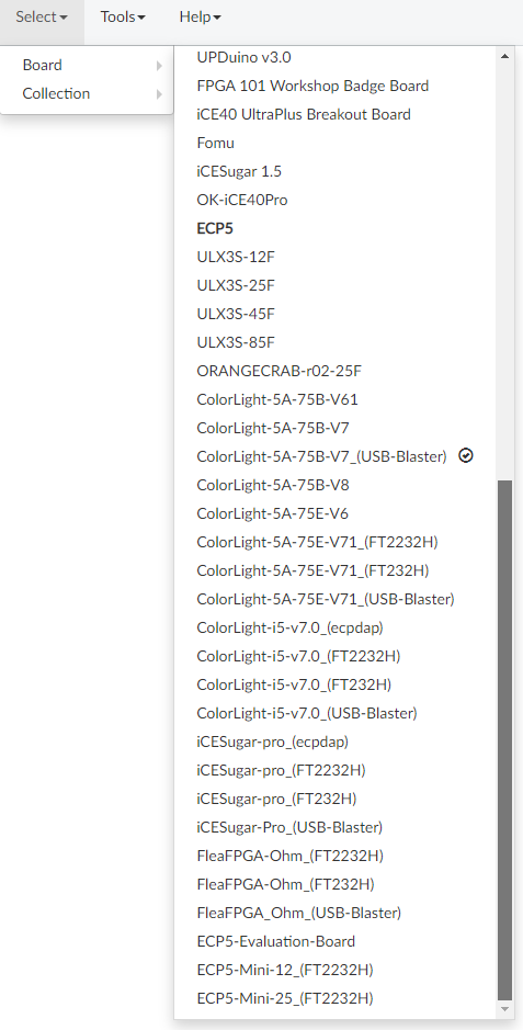
And in my Github that explains how to connect and configure the JTAG boards in Windows --> github.com/benitoss/ColorLight_FPGA_boards
You only need a FT2232H, FT232H or USB Blaster JTAG programmer
More information in : icestudio.io/
And in my Github that explains how to connect and configure the JTAG boards in Windows --> github.com/benitoss/ColorLight_FPGA_boards
Attachments:
Last edit: 18 Apr 2022 04:35 by benitoss.
The following user(s) said Thank You: tommylight, tuzki
Please Log in or Create an account to join the conversation.
- tuzki
-

- Offline
- Senior Member
-
Less
More
- Posts: 48
- Thank you received: 1
20 Apr 2022 01:42 #240713
by tuzki
Replied by tuzki on topic ColorCNC Colorlight 5A-75E/5A-75B as FPGA controller board
Can this IDE open the firmware of ColorCNC posted in the forum.
Please Log in or Create an account to join the conversation.
Moderators: PCW, jmelson
Time to create page: 1.787 seconds