Pete's Cincinatti Arrow 500 Retrofit...
- PetefromTn
- Offline
- Senior Member
-

Less
More
- Posts: 58
- Thank you received: 0
11 Mar 2013 20:56 - 11 Mar 2013 20:58 #31225
by PetefromTn
Replied by PetefromTn on topic Cincinatti Arrow 500 retrofit questions.....
Changed thread title to Pete's Cincinatti Arrow 500 Retrofit.... LOL
Pete
Pete
Last edit: 11 Mar 2013 20:58 by PetefromTn.
Please Log in or Create an account to join the conversation.
- BigJohnT
-

- Offline
- Administrator
-

Less
More
- Posts: 7000
- Thank you received: 1176
11 Mar 2013 22:10 #31233
by BigJohnT
Replied by BigJohnT on topic Cincinatti Arrow 500 retrofit questions.....
Looking Good!
John
John
Please Log in or Create an account to join the conversation.
- PetefromTn
- Offline
- Senior Member
-
Less
More
- Posts: 58
- Thank you received: 0
11 Mar 2013 23:37 #31240
by PetefromTn
Replied by PetefromTn on topic Cincinatti Arrow 500 retrofit questions.....
Hey John,
Thanks man I am trying to do this nicely and end up with a reliable machine here. Any suggestions or ideas will be seriously considered. The pendant is kinda blank looking As I am waiting on some other stuff and I still have to install some more momentary buttons I have here. Peace
Pete
Thanks man I am trying to do this nicely and end up with a reliable machine here. Any suggestions or ideas will be seriously considered. The pendant is kinda blank looking As I am waiting on some other stuff and I still have to install some more momentary buttons I have here. Peace
Pete
Please Log in or Create an account to join the conversation.
- PetefromTn
- Offline
- Senior Member
-
Less
More
- Posts: 58
- Thank you received: 0
12 Mar 2013 01:04 #31245
by PetefromTn
Replied by PetefromTn on topic Cincinatti Arrow 500 retrofit questions.....
Update....
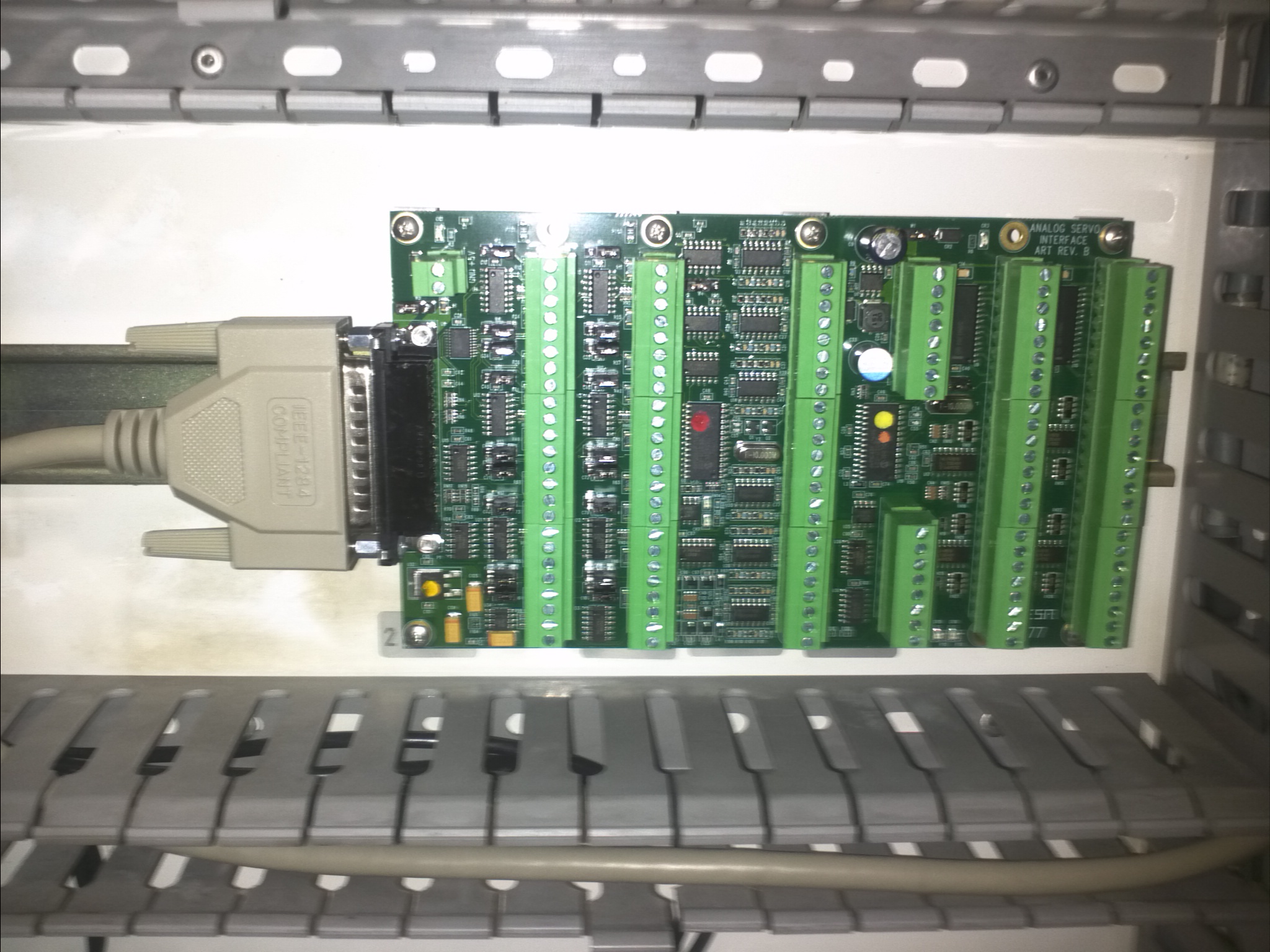
Just received another package from the fine folks at Mesanet. I got my ten foot cable and my din rail mounting kits. This was received much faster than I thought it would. The din kits are nice quality and have aluminum spreading bars to support the card. Oleg at Mesanet advised me to order two kits and I am glad I took his advice. It makes mounting the 7i77 card a piece of cake and more importantly it supports the entire length of the card so when I start plugging and screwing down wires it will hopefully keep the board from cracking on me. The boards also have nice removable terminal strips which should also make things easier. All in all I am extremely impressed with Mesanet so far.
Now that I can hook my cable to the computer I can try to power the 7i77 card with the 24volts field power and see if linuxcnc recognizes it. Then I can start
wiring the rest of the IO up. Pretty sweet to be finally on my way with this stuff...peace
Pete
Please Log in or Create an account to join the conversation.
- PetefromTn
- Offline
- Senior Member
-
Less
More
- Posts: 58
- Thank you received: 0
13 Mar 2013 00:36 #31288
by PetefromTn
Replied by PetefromTn on topic Cincinatti Arrow 500 retrofit questions.....
Well it appears as tho we have hit a snag. It was not unexpected but I had hoped it would not be the case with my machine. The y axis motor has a large mil-spec barrel connector that is mounted atop a square post that you can see in the pictures I posted further up the page. Between the square protrusion and the barrel connector plug it sits above the body of the motor by almost four and a half inches. Pretty freaking ridiculous actually but it is what it is. My pal Lee in England ran into the same issue on his Cincinnati Arrow retrofit. I believe he told me that he was forced to solder the power wires directly onto the pins on the motor plug. Then he sealed the whole thing with some kinda waterproof gunk to keep the wires from touching and keep coolant and debris out of the wiring. Honestly the motor is inside the column on the machine but it is behind several guards. I did find chips inside that area but they were on the floor of the opening and not really on the motor body at all
I am also running into an issue with the Teco servo drives. They have some freaking obscure 50pin connection on them for the IO and apparently it is an 3M 10150-3000series connector. The cables I was hoping to buy and just cut to screw down the wires into the mesa cards are proving difficult to find. They are apparently HPCN50 model ends that match the 3m plug. Trying to find a male-male setup has been impossible. I bought the connectors from Machmotion which are solderable type but they are as I said 50pin and the connections are TINY!! I only actually need about 15 of the pins and I may try to use an svga cable to make the harnesses. Gonna be a bitch and I hate soldering as it is.....
Anyway I am slowly working on the thing going one circuit at a time. Any advice or suggestions will be appreciated....peace
Pete
Please Log in or Create an account to join the conversation.
- JR1050
-

- Offline
- Platinum Member
-

Less
More
- Posts: 450
- Thank you received: 33
13 Mar 2013 07:15 #31304
by JR1050
Replied by JR1050 on topic Pete's Cincinatti Arrow 500 Retrofit...
I would mount the cannon connector on the back of the motor housing,90 deg from where it is and use a right angle cable connector,that should solve your space issue.
I recently finished a Cinci lathe and I kept most of the original wiring.I had the original wiring diagram ,so, I didnt have to re invent the wheel. It also allows me to call tech support at MAG if I have a problem that is not control related.Just sayn.....I think you will find you will need some additional buttons ,as running the machine solely with the mouse is a pia.
To use encoder feedback with the Wj200 you need the expansion card and you will need a large braking resistor if you want anything that resembles a quick spindle stop. Use shielded cable for your drives!!!
When i set up a new machine,I use a reg hard drive,only because you will be constantly changing the files and SSD have limited write ability.When I get the logic proven,then i put the ssd in.
If you are awful at soldering,try a local electronics repair or custom cable builder,you will save yourself tons of aggravation chasing bad solder joints.I would be interested in purchasing or doing some swapping for your old motors and drives.I have a brand new never used Mesa 7i73.It might be useful for the buttons you will find you need.Good luck,looks good!!
The following user(s) said Thank You: PetefromTn
Please Log in or Create an account to join the conversation.
- PetefromTn
- Offline
- Senior Member
-
Less
More
- Posts: 58
- Thank you received: 0
13 Mar 2013 07:46 #31305
by PetefromTn
Replied by PetefromTn on topic Pete's Cincinatti Arrow 500 Retrofit...
Thanks for your reply, I cannot see how I can mount the cannon connector on the back of the motor housing and the cables I bought are already setup with the 90 degree fitting. Can you elaborate on this? Honestly I took out all of the original wiring simply because I did not trust it anymore. I had many failures of the original control and decided after several expensive repairs that if I was going to retrofit I would basically start from scratch by choice.
I honestly do not agree that you need a panel full of buttons to run the machine, my last machine ran fine and had zero buttons short of an estop. However I have setup the panel yesterday with the three industrial buttons I have here and actually already installed them in the panel.
I have not really looked into the wj200 manual all that much as I just received it but I actually thought I read that it already has encoder feedback into the drive and honestly I was going to run it into the mesa card for feedback into linuxCNC. The braking resistor is something I have read about and I figure I will cross that bridge after I see how it works the way it comes.
Your comments regarding the solid state hard drive are kinda interesting. I have heard that they are not fond of many many write cycles but honestly why would setting up linux take that many write cycles as to cause an issue? As I understand Linux is much different than windows about constantly writing and rewriting stuff but not sure how that changes things. Once I get the machine working the way I want I was planning to do a drive mirror or something and save the information in case of a failure of the drive.
I never said I was awful at soldering I was actually trained in precision soldering in the Coast Guard as I was an aviation electronics technician. That was honestly almost 20 years ago tho and the reality is that while I am not terrible at it I honestly just don't like to do it and these pins are so concentrated on the connector that whoever does it will be in for a challenge.
As far as trading the old motors and drives, well they are already sold as that is what actually paid for all of this new stuff. The only stuff I have left is the two original transformers that were in the machine. I even sold my phase converter to fund this. This has been a long time coming and there have been no shortage of disappointments along the way.
You sound like you know a thing or two about this stuff, I definitely am interested in your advice and I appreciate your input here. The comment you made about the shielded cables for the drives I assume you are talking about the I/O cables right? I am actually a little concerned about the placement of the spindle drive in the machine as the drive is kinda difficult to put anywhere where it will not be near the low voltage stuff. The entry point of the cables and the fact that I wanted to keep the distance as short as possible and as far away from the rest of the components as I possibly can has made all of this difficult to attain. I put the coolant vfd down in the very bottom of the cabinet so that should make the least noise issues possible. Going to continue on trying to do this the best way possible. Peace
Pete
Please Log in or Create an account to join the conversation.
- JR1050
-
- Offline
- Platinum Member
-
Less
More
- Posts: 450
- Thank you received: 33
13 Mar 2013 08:31 #31306
by JR1050
Replied by JR1050 on topic Pete's Cincinatti Arrow 500 Retrofit...
In your pic,the motor is encoder up with the power connector mounted on top of a square standoff that is part of the motor housing. If you put the cannon plug on the side of the standoff that is parallel with the encoder housing(as pictured) you will get the space.This will require a block off plate for where the original connector was and some holes drilled on the new mounting surface.
My only point in rewiring the machine is the original wiring scheme worked,was safe and allows you to talk with Cinnci if you have a question.The first machine i retro'd was a hardinge and I replaced all the wiring as it was shot,I did however use a proven diagram for the machine,as it happens,it was for my Cinci lathe!! I had it and the original was for an old GE 550 NC and wouldnt work.. In that respect, Im on my own with the machine, but then again,no one at hardinge knows anything about an hnc.Your machine is more like my Cinci lathe,which I changed very little on.
As for the WJ, if you want to use an encoder for speed control (closed loop with with the drive),you need the expansion card,and trust me,start looking for a braking resistor.
I find physical buttons easier then a mouse,I can watch the machine,not the screen.Its a personal thing.When a table is moving at 600 plus inches per minute,Id rather watch the machine,not try to find the stupid feed hold icon!!!
I know nothing of your soldering prowess, I cant see the little pins anymore.I bought crimpers....and if I need special cables made,I have someone with the right equipment make them. Use shielded cabling for your encoder and drive signals.Regular i/o really doesnt matter,as Cinci uses plain wiring. Id mount the spindle drive in the same place as the original,easy.....
Id strap a motor to a bench and set up a test run to get everything "kinda working". This is a big project. I know machines,done a few non Emc retofits a few Emc retofits and presently work as a service engineer.I have a few more projects in my future with the Emc, a four axis Matsurra and what will be a 5 axis Brown & Sharpe
when I get a block of free time.
The thing to keep in mind is that the original machine and control manufacturer have teams who spent lots of time working the in and outs of a particular machine,to get the machine moving is relatively simple,to get the machine safe,functional and reliable is another thing all together,you have to consider every possible problem and work around it.It is here the original manuals will be invaluable,as they list all potential problems in the alarm section.
Please Log in or Create an account to join the conversation.
- andypugh
-

- Offline
- Moderator
-

Less
More
- Posts: 23377
- Thank you received: 4966
13 Mar 2013 15:31 #31312
by andypugh
I think that this is probably the best plan. The first step is probably to unscrew the mil-spec connector socket and see how much slack/bend there is in the wires.
Moving the connector to another face of the block is probably the only choice. It is possible that the block is as big as it is precisely because there are such options.
Alternatively, you may be able to mount a right-angle socket in place of the existing one. But it is likely that the motor wires are crimped and latched into the socket, and you need special, expensive tools to extract the pins.
Replied by andypugh on topic Pete's Cincinatti Arrow 500 Retrofit...
In your pic,the motor is encoder up with the power connector mounted on top of a square standoff that is part of the motor housing. If you put the cannon plug on the side of the standoff that is parallel with the encoder housing(as pictured) you will get the space.This will require a block off plate for where the original connector was and some holes drilled on the new mounting surface.
I think that this is probably the best plan. The first step is probably to unscrew the mil-spec connector socket and see how much slack/bend there is in the wires.
Moving the connector to another face of the block is probably the only choice. It is possible that the block is as big as it is precisely because there are such options.
Alternatively, you may be able to mount a right-angle socket in place of the existing one. But it is likely that the motor wires are crimped and latched into the socket, and you need special, expensive tools to extract the pins.
Please Log in or Create an account to join the conversation.
- PetefromTn
- Offline
- Senior Member
-
Less
More
- Posts: 58
- Thank you received: 0
13 Mar 2013 18:28 #31320
by PetefromTn
Replied by PetefromTn on topic Pete's Cincinatti Arrow 500 Retrofit...
Thanks guys,
As I said before the original setup was problematic as least as far as the drives were concerned. Understand that when I say that I gutted the machine I am referring to the electronics cabinet mostly and the pendant. The entire toolchanger assembly has not been touched nor has any of the original limits or home switches or the pneumatic power drawbar or the spindles position sensor assemblies. Honestly I am simply removing the three axis and spindle drives and the entire pendant internals and replacing them with a PC and installing brand new drives in the back. The mesa card will replace much of the original control setup and all of the io will go to that point.
I am of course using shielded cabling for the drives control circuit harnesses and the new axis motors and drives I bought with complete new power and encoder harnesses. They will be just basically plug and play with the obvious exception of the Y axis issue.
I am right now trying to get my estop circuit figured out because I need to get an input into linuxcnc so the machine knows when I hit a estop button. I am also working on hooking up my home switches. Still lots to do here. I will be installing a new encoder in place of the resolver inside the spindle motor and removing the resolver harness most likely when I do. The toolchanger setup will be the last thing I work on with the machine right now I am just trying to get the basic three axes working and the limits and homes and the spindle sans feedback. Once that is working properly and safely I will move onto the rest of the machine. Last nights I was reading thru the mesa literature about the 5i25/7i77 combo and how to configure the switches. Peace
Pete
Please Log in or Create an account to join the conversation.
Time to create page: 0.147 seconds