Pete's Cincinatti Arrow 500 Retrofit...
- PetefromTn
- Offline
- Senior Member
-

Less
More
- Posts: 58
- Thank you received: 0
14 Mar 2013 01:02 #31349
by PetefromTn
Replied by PetefromTn on topic Pete's Cincinatti Arrow 500 Retrofit...
Okay guys thanks to the help of big john and Pete at mesa I have figured out how to poke around in linux as well as install the firmware for the 5i25 and I just tried to run the PncConf setup and it is recognizing the 5i25 card as well as giving me the options to configure the 7I77 card as well. SO that is a big deal for me and now I can start hooking things into the 7i77 board and start testing them. I am going to start hooking up the home switches and whatnot and take this one simple circuit at a time. Hopefully I can do it successfully. I can already see that there are quite a few settings for the drives and encoders I will need to find the information on to setup properly but that should be easy to find. The 7i77 card is all lit up except for the single red led on the input area not sure what it means just yet. Perhaps there needs to be at least one input to turn it off? I am reading thru the manual now to sort that.
I am seriously considering a suggestion made to me by the folks at wolf automation. They basically said that all of the contactors and relays that were in the machine were kind of old school stuff. Everything now is solid state and on top of that he told me that the drives for the axes as well as the spindle I purchased are all setup to do internally everything that the contactors and relays did externally on the old setup. IE the estop circuit and thermal overload/current overload etc etc are all built into the drives. He said that because of this you can now run all of your drives directly off the main disconnect. I was kinda surprised by this but he told me of several good reasons for it not the least of which is the noise and spikes they can produce when they fire. He told me that basically I can setup my estop and limits and control circuits right off the drives and that when the drives are in estop they depower the motor sections the same way the contactor removing power entirely would do only the power to the drive stays on as well as the encoder feedback. He told me that they do this themselves every day now on machines they work on and panels they design for their customers.
After hearing all of this and actually knowing another fellow who has the same exact drives as I do configured this way I am kinda leaning towards doing it the same way. I would be interested in hearing ideas and suggestions about this. It sure would be nice to not have to use any relays and contactors in the machine and rely on the 24v control circuits to do all of it. Keep in mind my machine will be running entirely on single phase input power here too. I am right now trying to figure out a good way to setup the limits and estop circuit along with a limit override momentary button to switch off the drives in this manner. Thanks and peace
Pete
Please Log in or Create an account to join the conversation.
- PCW
-

- Online
- Moderator
-

Less
More
- Posts: 18857
- Thank you received: 5208
14 Mar 2013 01:08 #31351
by PCW
Replied by PCW on topic Pete's Cincinatti Arrow 500 Retrofit...
Looking at the TECO drive manual I do no see any disconnect that runs from hardware inputs (all the inputs seem to be just logical inputs that you can re-assign functions)
I may be old school but I would not depend on a ESTOP circuit that goes through OPTOS and maybe software in the drive
I may be old school but I would not depend on a ESTOP circuit that goes through OPTOS and maybe software in the drive
Please Log in or Create an account to join the conversation.
- PetefromTn
- Offline
- Senior Member
-
Less
More
- Posts: 58
- Thank you received: 0
14 Mar 2013 01:30 #31353
by PetefromTn
Replied by PetefromTn on topic Pete's Cincinatti Arrow 500 Retrofit...
Are you sure it is going thru optos, we are talking about removing the 24v signal entirely from that estop/Servo enable circuit. Still tinkering with this setup but that is how my pal Joel's machine works and it has been running safely for some time now. I tried to call him just now to ask about the specifics of it but he didn't answer. I am going to maybe send him an email and ask again. I already have the contactors and some of the relays necessary to do it the way I had originally intended but this option should be much less noise prone which can only be a good thing. That and it is probably easier to wire up. Thanks for all of your help guys this is getting interesting now LOL...peace
Pete
Pete
Please Log in or Create an account to join the conversation.
- PCW
-
- Online
- Moderator
-
Less
More
- Posts: 18857
- Thank you received: 5208
14 Mar 2013 01:39 #31356
by PCW
Replied by PCW on topic Pete's Cincinatti Arrow 500 Retrofit...
The manual shows the TECO estop signals as just one of the 13 general purpose inputs (see 2-14 and 2-25)
Please Log in or Create an account to join the conversation.
- PetefromTn
- Offline
- Senior Member
-
Less
More
- Posts: 58
- Thank you received: 0
14 Mar 2013 02:26 #31358
by PetefromTn
Replied by PetefromTn on topic Pete's Cincinatti Arrow 500 Retrofit...
Peter,
Yes I agree but what we are talking about is putting the 24v input to that entire circuit on the estop limit setup so hitting an estop or limit will shut it down completely. Again I am not sure of the particulars but I will try to contact Joel and see how his is setup.
I am on the fence about this and as I said I already have the stuff to go the contractors route if necessary. I just want it to be safe and reliable no matter how it gets wired. Peace
Pete
Please Log in or Create an account to join the conversation.
- PetefromTn
- Offline
- Senior Member
-
Less
More
- Posts: 58
- Thank you received: 0
15 Mar 2013 08:08 #31435
by PetefromTn
Replied by PetefromTn on topic Pete's Cincinatti Arrow 500 Retrofit...
Hey guys,
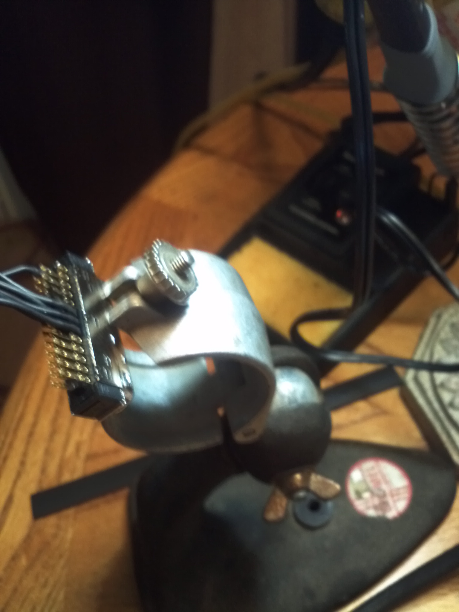
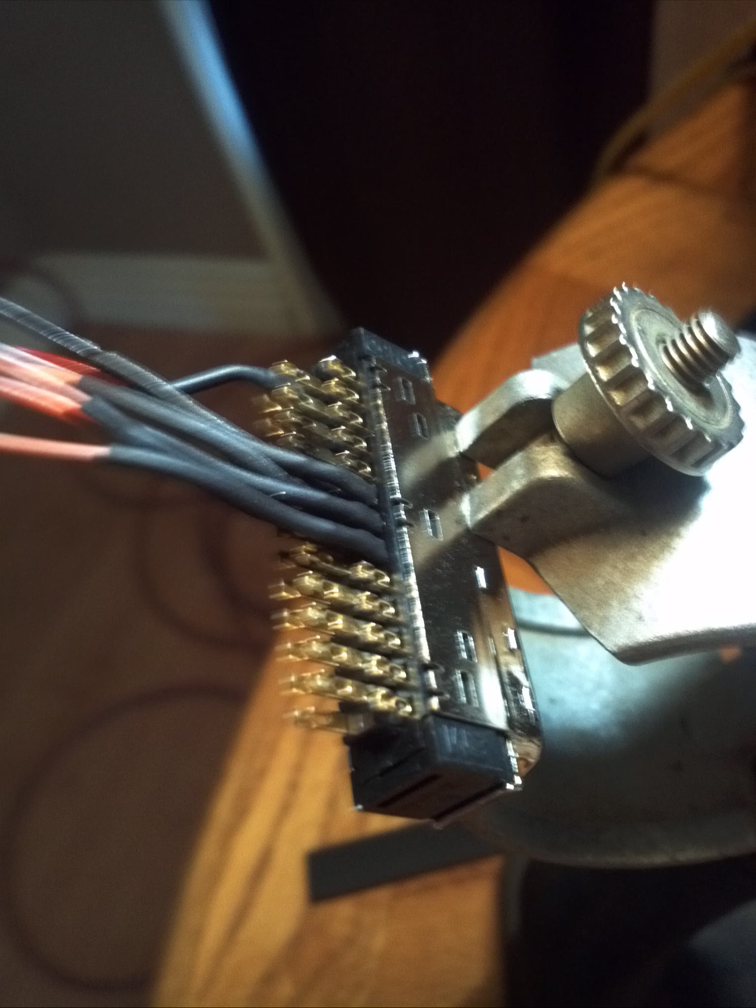
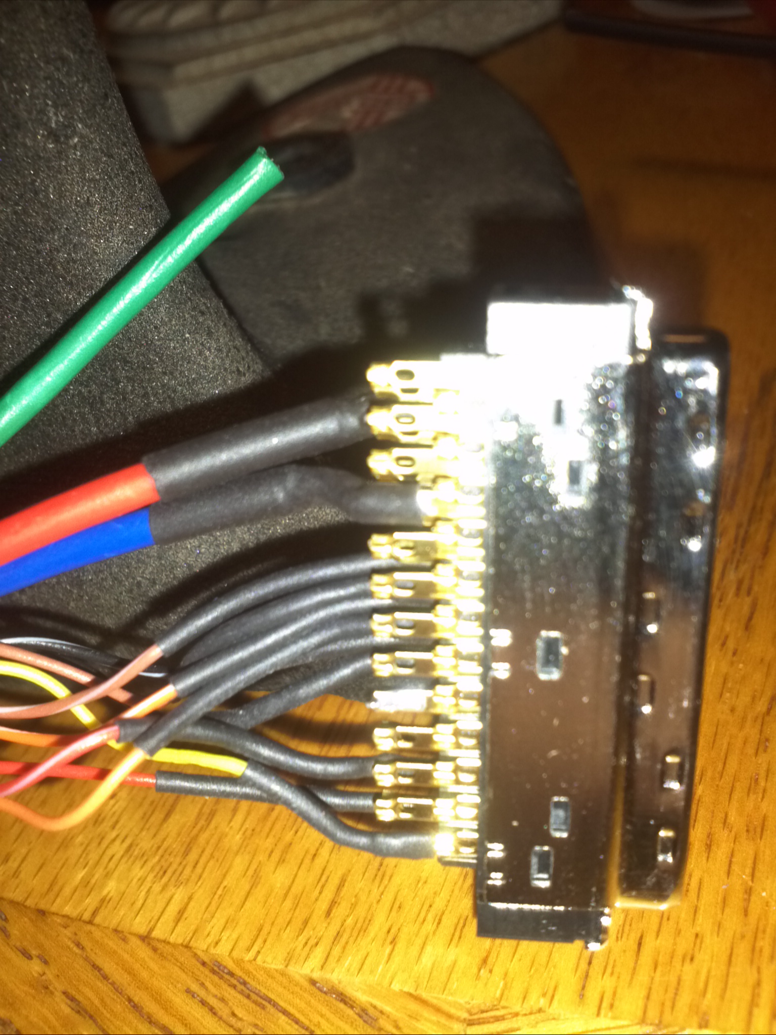
Well I spent a LOT of time today working on my harnesses for the axis drives. The connector is called the CN1 on the teco drives and I have gotten almost all three done. I am now working on the Z axis harness. The only real difference between the Z axis and the others is that the Z axis brake is wired into this connector here. I called Machmotion today about it and asked them the proper way to wire their brake system up. Basically the system has a small 110v powered 24v power supply that is din rail mountable and there is a 24v mechanical relay that is also din rail mountable in the system. They have the relay supplying power from the power supply to the brake thru the relay and it is triggered by a 24v coil circuit going from pin 20 which is the zero speed pin to the pin 47 which is the DCIM pin. This apparently works such that once the drive is at servo off the brake is enabled. We are jumpering the pin 45 to pin47 so that the 24v power circuit is energized throughout the drives system.
Here is my pin arrangement:
pin1.......servo on
pin35.....Encoder A
pin36.... Encoder /A
pin37.....Encoder B
pin38.....Encoder /B
pin39.....Encoder Z
pin40.....Encoder /Z
pin 26....Analog +/-10vdc
pin29.....Analog GND
pin19.....Alarm signal
pin45.....jumpered to pin 47
pin48.....Ground
pin47.....Servo Brake+(only on Z axis)
pin20.....Servo Brake-(only on Z axis)
There is a green wire remaining and while I think we have everything we need wired up I left it there for now in case we missed any important pins...
I hope we got this right I think it is correct after reading the manual and the pinout several times now. Anyways we are using a brand new SVGA cable which is shielded nicely for these signals and fits the cover for the connectors nicely as well. I am unclear as to whether or not I should secure the cable's shield wire to pin50 at the drive or not I have heard it both ways but most seem to say that I should only ground the shielding at the 7I77 card. Any input on this would be appreciated. Once I get these finished and buttoned up we should be ready to test motors very soon. I am going to need to wait for my 24v relays that will be for the power circuits to arrive before I can apply power to the drives for testing purposes. I am looking forward to seeing motors turn on a test bench soon.
Anyways here are some pictures of todays work....peace
Pete
Please Log in or Create an account to join the conversation.
- PetefromTn
- Offline
- Senior Member
-
Less
More
- Posts: 58
- Thank you received: 0
19 Mar 2013 05:03 - 19 Mar 2013 05:06 #31562
by PetefromTn
Replied by PetefromTn on topic Pete's Cincinatti Arrow 500 Retrofit...
Okay guys and gals...
Been working on the machine today. I finally finished the I/O cables for interfacing the drives to the 7i77. I wanted to test a motor and drive out to see if I can get motor movement. I hooked up the drive to power and hooked up the encoder and enable wires to the 7i77. Then I went in and powered everything up. Nothing smoked so that was nice. Then I opened up the computer and tried to run thru a Pncconf setup. I was only trying to configure the basics and just enable the X axis drive but it was not happy until I enabled the rest of the axes. I managed to get thru that setup with Connor's help and when LinuxCNC tried to run I got an error file. I am posting this file here to see what you guys can tell me. Completely new to this so gotta take it for granted I don't know jack here. Anyways I noticed that the driver watchdog is still lit on the 7I77 card. Any suggestions? Here is the error file..peace
Print file information:
RUN_IN_PLACE=no
LINUXCNC_DIR=
LINUXCNC_BIN_DIR=/usr/bin
LINUXCNC_TCL_DIR=/usr/lib/tcltk/linuxcnc
LINUXCNC_SCRIPT_DIR=
LINUXCNC_RTLIB_DIR=/usr/realtime-2.6.32-122-rtai/modules/linuxcnc
LINUXCNC_CONFIG_DIR=
LINUXCNC_LANG_DIR=/usr/share/linuxcnc/tcl/msgs
INIVAR=inivar
HALCMD=halcmd
LINUXCNC_EMCSH=/usr/bin/wish8.5
LINUXCNC - 2.6.0-pre0-3567-gcb53192
Machine configuration directory is '/home/pete/linuxcnc/configs/Cinciatti_Arrow__500'
Machine configuration file is 'Cinciatti_Arrow__500.ini'
INIFILE=/home/pete/linuxcnc/configs/Cinciatti_Arrow__500/Cinciatti_Arrow__500.ini
PARAMETER_FILE=linuxcnc.var
TASK=milltask
HALUI=halui
DISPLAY=axis
DISABLE_SERVER=
SERVER_PATH=
SERVER_ARGS=
SERVER_LOG=
Starting LinuxCNC...
Starting redis server program:
redis server started as: 'redis-server ', logging to: /dev/null
Starting LinuxCNC server program: linuxcncsvr
Loading Real Time OS, RTAPI, and HAL_LIB modules
Starting LinuxCNC IO program: io
io started
halcmd loadusr io started
Starting HAL User Interface program: halui
Shutting down and cleaning up LinuxCNC...
Running HAL shutdown script
Killing task linuxcncsvr, PID=2022
Killing task redis-server, PID=2021
Removing HAL_LIB, RTAPI, and Real Time OS modules
Removing NML shared memory segments
Cleanup done
Debug file information:
Can not find -sec MOT -var MOT -num 1
Can not find -sec IO -var IO -num 1
Can not find -sec LINUXCNC -var NML_FILE -num 1
Can not find -sec EMC -var NML_FILE -num 1
Can not find -sec REDIS -var DISABLE_SERVER -num 1
Can not find -sec REDIS -var SERVER_PATH -num 1
Can not find -sec REDIS -var SERVER_ARGS -num 1
Can not find -sec REDIS -var SERVER_LOG -num 1
Cinciatti_Arrow__500.hal:44: Pin 'bldc.0.rawcounts' does not exist
2022
PID TTY STAT TIME COMMAND
2021
PID TTY STAT TIME COMMAND
Stopping realtime threads
Unloading hal components
Kernel message information:
[ 2728.100264] I-pipe: Domain RTAI registered.
[ 2728.100279] RTAI[hal]: <3.8.1> mounted over IPIPE-NOTHREADS 2.6-03.
[ 2728.100284] RTAI[hal]: compiled with gcc version 4.4.3 (Ubuntu 4.4.3-4ubuntu5) .
[ 2728.100389] RTAI[hal]: mounted (IPIPE-NOTHREADS, IMMEDIATE (INTERNAL IRQs DISPATCHED), ISOL_CPUS_MASK: 0).
[ 2728.100395] PIPELINE layers:
[ 2728.100400] fa0dee20 9ac15d93 RTAI 200
[ 2728.100405] c085cb20 0 Linux 100
[ 2728.146192] RTAI[malloc]: global heap size = 2097152 bytes, <BSD>.
[ 2728.146802] RTAI[sched]: IMMEDIATE, MP, USER/KERNEL SPACE: <with RTAI OWN KTASKs>, kstacks pool size = 524288 bytes.
[ 2728.146814] RTAI[sched]: hard timer type/freq = APIC/12500378(Hz); default timing: periodic; linear timed lists.
[ 2728.146822] RTAI[sched]: Linux timer freq = 250 (Hz), TimeBase freq = 1799845000 hz.
[ 2728.146828] RTAI[sched]: timer setup = 999 ns, resched latency = 2944 ns.
[ 2728.146954] RTAI[usi]: enabled.
[ 2728.223166] RTAI[math]: loaded.
[ 2728.355610] hm2: loading Mesa HostMot2 driver version 0.15
[ 2728.361432] hm2_pci: loading Mesa AnyIO HostMot2 driver version 0.7
[ 2728.361491] hm2_pci 0000:05:00.0: PCI INT A -> GSI 20 (level, low) -> IRQ 20
[ 2728.361499] hm2_pci: discovered 5i25 at 0000:05:00.0
[ 2728.363703] hm2/hm2_5i25.0: Smart Serial Firmware Version 35
[ 2728.668316] hm2/hm2_5i25.0: 34 I/O Pins used:
[ 2728.668326] hm2/hm2_5i25.0: IO Pin 000 (P3-01): IOPort
[ 2728.668332] hm2/hm2_5i25.0: IO Pin 001 (P3-14): IOPort
[ 2728.668338] hm2/hm2_5i25.0: IO Pin 002 (P3-02): IOPort
[ 2728.668346] hm2/hm2_5i25.0: IO Pin 003 (P3-15): Smart Serial Interface #0, pin TxData1 (Output)
[ 2728.668354] hm2/hm2_5i25.0: IO Pin 004 (P3-03): Smart Serial Interface #0, pin RxData1 (Input)
[ 2728.668361] hm2/hm2_5i25.0: IO Pin 005 (P3-16): Smart Serial Interface #0, pin TxData0 (Output)
[ 2728.668369] hm2/hm2_5i25.0: IO Pin 006 (P3-04): Smart Serial Interface #0, pin RxData0 (Input)
[ 2728.668377] hm2/hm2_5i25.0: IO Pin 007 (P3-17): Muxed Encoder Select #0, pin Mux Select 0 (Output)
[ 2728.668384] hm2/hm2_5i25.0: IO Pin 008 (P3-05): Muxed Encoder #0, pin Muxed A (Input)
[ 2728.668392] hm2/hm2_5i25.0: IO Pin 009 (P3-06): Muxed Encoder #0, pin Muxed B (Input)
[ 2728.668399] hm2/hm2_5i25.0: IO Pin 010 (P3-07): Muxed Encoder #0, pin Muxed Index (Input)
[ 2728.668406] hm2/hm2_5i25.0: IO Pin 011 (P3-08): Muxed Encoder #1, pin Muxed A (Input)
[ 2728.668414] hm2/hm2_5i25.0: IO Pin 012 (P3-09): Muxed Encoder #1, pin Muxed B (Input)
[ 2728.668421] hm2/hm2_5i25.0: IO Pin 013 (P3-10): Muxed Encoder #1, pin Muxed Index (Input)
[ 2728.668429] hm2/hm2_5i25.0: IO Pin 014 (P3-11): Muxed Encoder #2, pin Muxed A (Input)
[ 2728.668436] hm2/hm2_5i25.0: IO Pin 015 (P3-12): Muxed Encoder #2, pin Muxed B (Input)
[ 2728.668443] hm2/hm2_5i25.0: IO Pin 016 (P3-13): Muxed Encoder #2, pin Muxed Index (Input)
[ 2728.668450] hm2/hm2_5i25.0: IO Pin 017 (P2-01): IOPort
[ 2728.668455] hm2/hm2_5i25.0: IO Pin 018 (P2-14): IOPort
[ 2728.668461] hm2/hm2_5i25.0: IO Pin 019 (P2-02): IOPort
[ 2728.668467] hm2/hm2_5i25.0: IO Pin 020 (P2-15): IOPort
[ 2728.668472] hm2/hm2_5i25.0: IO Pin 021 (P2-03): IOPort
[ 2728.668478] hm2/hm2_5i25.0: IO Pin 022 (P2-16): IOPort
[ 2728.668484] hm2/hm2_5i25.0: IO Pin 023 (P2-04): IOPort
[ 2728.668490] hm2/hm2_5i25.0: IO Pin 024 (P2-17): Muxed Encoder Select #3, pin Mux Select 0 (Output)
[ 2728.668497] hm2/hm2_5i25.0: IO Pin 025 (P2-05): IOPort
[ 2728.668503] hm2/hm2_5i25.0: IO Pin 026 (P2-06): IOPort
[ 2728.668508] hm2/hm2_5i25.0: IO Pin 027 (P2-07): IOPort
[ 2728.668514] hm2/hm2_5i25.0: IO Pin 028 (P2-08): IOPort
[ 2728.668520] hm2/hm2_5i25.0: IO Pin 029 (P2-09): IOPort
[ 2728.668525] hm2/hm2_5i25.0: IO Pin 030 (P2-10): IOPort
[ 2728.668531] hm2/hm2_5i25.0: IO Pin 031 (P2-11): IOPort
[ 2728.668536] hm2/hm2_5i25.0: IO Pin 032 (P2-12): IOPort
[ 2728.668542] hm2/hm2_5i25.0: IO Pin 033 (P2-13): IOPort
[ 2728.668713] hm2/hm2_5i25.0: registered
[ 2728.668718] hm2_5i25.0: initialized AnyIO board at 0000:05:00.0
[ 2729.358300] hm2_5i25.0: dropping AnyIO board at 0000:05:00.0
[ 2729.358313] hm2/hm2_5i25.0: unregistered
[ 2729.358350] hm2_pci 0000:05:00.0: PCI INT A disabled
[ 2729.358967] hm2_pci: driver unloaded
[ 2729.363297] hm2: unloading
[ 2729.434818] RTAI[math]: unloaded.
[ 2729.476300] SCHED releases registered named ALIEN RTGLBH
[ 2729.541179] RTAI[malloc]: unloaded.
[ 2729.640034] RTAI[sched]: unloaded (forced hard/soft/hard transitions: traps 0, syscalls 0).
[ 2729.644899] I-pipe: Domain RTAI unregistered.
[ 2729.645056] RTAI[hal]: unmounted.
Last edit: 19 Mar 2013 05:06 by PetefromTn.
Please Log in or Create an account to join the conversation.
- PCW
-
- Online
- Moderator
-
Less
More
- Posts: 18857
- Thank you received: 5208
19 Mar 2013 05:28 #31564
by PCW
Replied by PCW on topic Pete's Cincinatti Arrow 500 Retrofit...
Cinciatti_Arrow__500.hal:44: Pin 'bldc.0.rawcounts' does not exist
This error happens because you enabled a inappropriate pncconf option
Forgot the option name but perhaps something with BLDC or AC servo
This error happens because you enabled a inappropriate pncconf option
Forgot the option name but perhaps something with BLDC or AC servo
Please Log in or Create an account to join the conversation.
- PetefromTn
- Offline
- Senior Member
-
Less
More
- Posts: 58
- Thank you received: 0
19 Mar 2013 05:51 #31566
by PetefromTn
Replied by PetefromTn on topic Pete's Cincinatti Arrow 500 Retrofit...
Pete.
Hey thanks for that information my freind. I honestly don't know how you guys can read all that stuff but I don't doubt I screwed up something in amongst the bazillion options in there. Now to fix that would I have to open PncConf again and start over or is there a way to modify the contents of the configuration somewhere else since LinuxCNC failed to load . I am hoping the latter ....
.... 
Pete
Hey thanks for that information my freind. I honestly don't know how you guys can read all that stuff but I don't doubt I screwed up something in amongst the bazillion options in there. Now to fix that would I have to open PncConf again and start over or is there a way to modify the contents of the configuration somewhere else since LinuxCNC failed to load . I am hoping the latter
.... Pete
Please Log in or Create an account to join the conversation.
- PCW
-
- Online
- Moderator
-
Less
More
- Posts: 18857
- Thank you received: 5208
19 Mar 2013 06:13 - 19 Mar 2013 06:18 #31568
by PCW
Replied by PCW on topic Pete's Cincinatti Arrow 500 Retrofit...
Probably better asked in the pncconf section...
"Use Brushless Motor Control" is the option you DONT want to enable
"Use Brushless Motor Control" is the option you DONT want to enable
Last edit: 19 Mar 2013 06:18 by PCW.
Please Log in or Create an account to join the conversation.
Time to create page: 0.418 seconds