New Machine Build: Bridgeport R2E4 Series II
- tightmopedman9
- Offline
- Senior Member
-

- Posts: 73
- Thank you received: 7
I added a spindle encoder and a spindle speed indicator in the gladeVCP panel. At max speed, ~5000RPM, the spindle speed jumps around by about 300 RPM. Is this a function of poor encoder implementation/output, or is that speed variability just normal for vari-speed heads? I tried passing the signal through a lowpass HAL filter, but it doesn't seem to have an effect on the output. My base thread is 20000, this is the relevant code:
setp scale.0.gain 60
setp lowpass.0.gain .5
net spindle-velocity => lowpass.0.in
net spindle-fb-filtered-rps lowpass.0.out => scale.0.in
net spindle-fb-filtered-rpm scale.0.out => gladevcp.hal_meter1
Is there any way to reduce significant figures in glade, or the signal that feeds a glade meter?
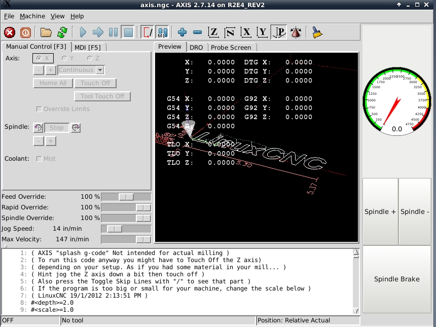
I also added buttons which interface with the pneumatic controls for the varispeed pulley adjustment.
Please Log in or Create an account to join the conversation.
- andypugh
-

- Offline
- Moderator
-

- Posts: 19861
- Thank you received: 4636
I would use HAL, it is more reliable. Userspace (and Python only runs in Userspace) can be interrupted by GUI stuff or any number of other things.I set up a simple gladeVCP panel to interface with the brake. I need to add logic to make sure that it can't get enabled while the spindle is spinning. I'm not sure how to do this though. Would it be a python, or HAL operation?
use a "near" comp on spindle speed and an "and2" if you only want to engage it when the spindle is stopped, or just the and2 and an inverted version of "motion.spindle-is-on" if you want to be able to brake the spindle to a stop from running.
It's very common with encoders, it doesn't take much to make the velocity output unsteady.I added a spindle encoder and a spindle speed indicator in the gladeVCP panel. At max speed, ~5000RPM, the spindle speed jumps around by about 300 RPM. Is this a function of poor encoder implementation/output
I tried passing the signal through a lowpass HAL filter, but it doesn't seem to have an effect on the output
That's the normal approach, but a gain of 0.5 only filters for 2 thread cycles. Try 0,9, or 0.99.
Please Log in or Create an account to join the conversation.
- andypugh
-
- Offline
- Moderator
-
- Posts: 19861
- Thank you received: 4636
I would use HAL, it is more reliable. Userspace (and Python only runs in Userspace) can be interrupted by GUI stuff or any number of other things.I set up a simple gladeVCP panel to interface with the brake. I need to add logic to make sure that it can't get enabled while the spindle is spinning. I'm not sure how to do this though. Would it be a python, or HAL operation?
use a "near" comp on spindle speed and an "and2" if you only want to engage it when the spindle is stopped, or just the and2 and an inverted version of "motion.spindle-is-on" if you want to be able to brake the spindle to a stop from running.
It's very common with encoders, it doesn't take much to make the velocity output unsteady.I added a spindle encoder and a spindle speed indicator in the gladeVCP panel. At max speed, ~5000RPM, the spindle speed jumps around by about 300 RPM. Is this a function of poor encoder implementation/output
I tried passing the signal through a lowpass HAL filter, but it doesn't seem to have an effect on the output
That's the normal approach, but a gain of 0.5 only filters for 2 thread cycles. Try 0.1, or 0.01.
[edit] Had the gain inverted
Please Log in or Create an account to join the conversation.
- tightmopedman9
- Offline
- Senior Member
-
- Posts: 73
- Thank you received: 7
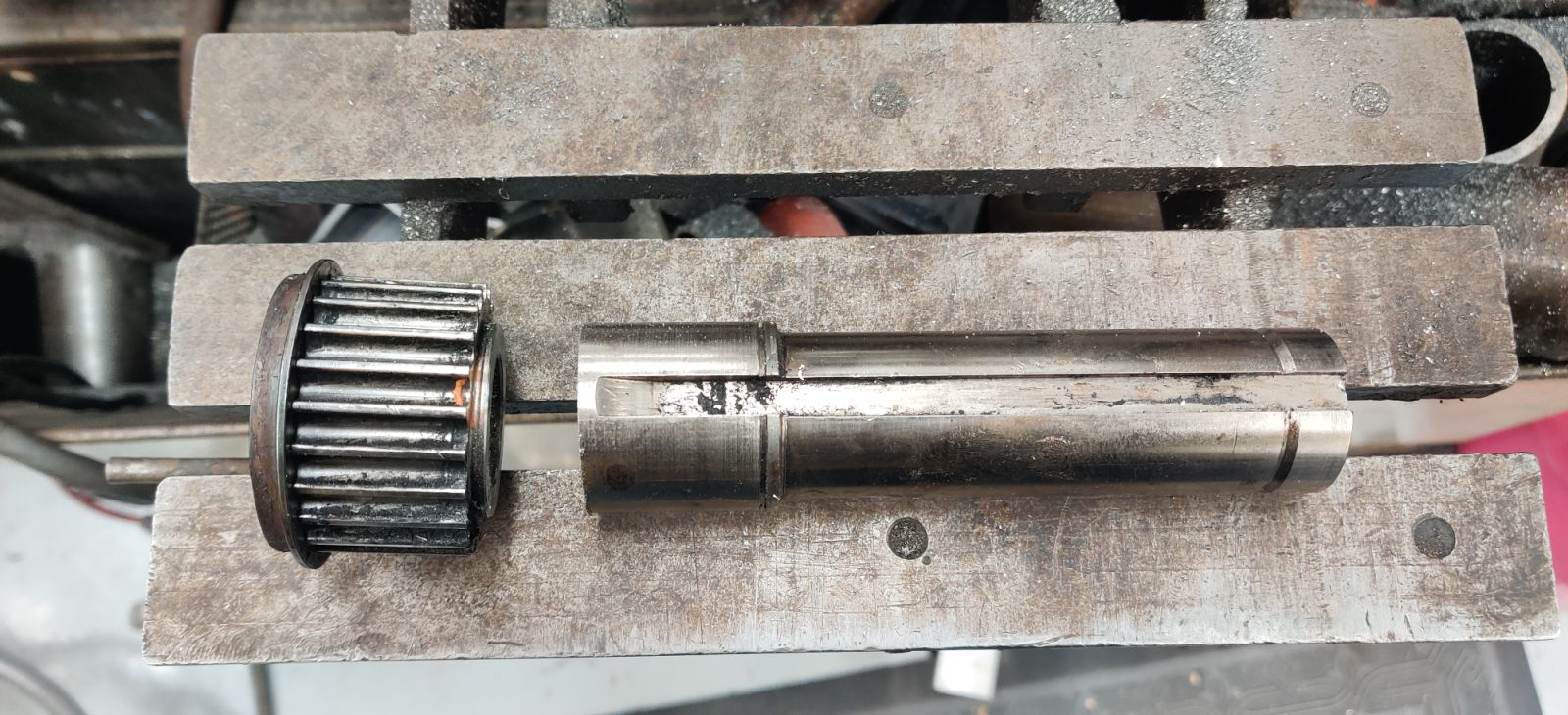
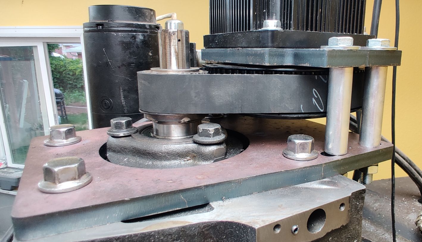
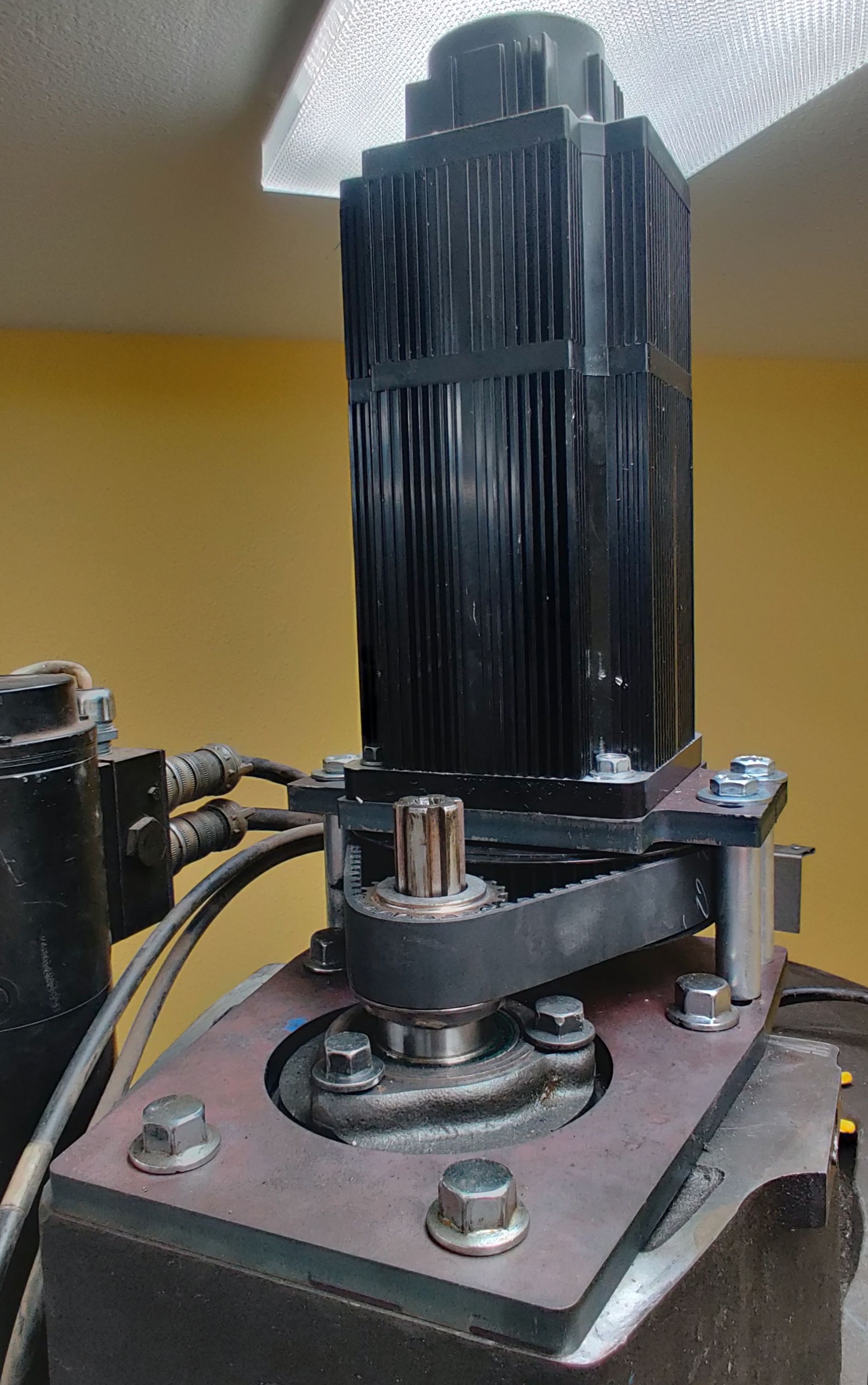
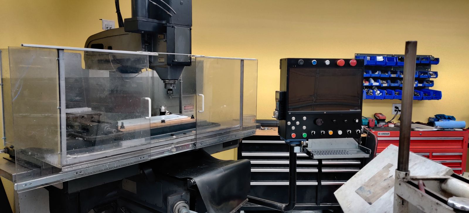
I purchased a Chinese 2.6kW AC servo motor and drive combo with a maximum speed of 2500RPM to replace the 2 HP motor the mill originally came with. Since 2.6kW is equivalent to ~3.5HP, I thought I'd have more power than the original setup. However, I forgot about accounting for the gear reduction necessary to spin the spindle at the desired speed of 7000RPM. Luckily, I was able to send the 2.6kW servo back in exchange for a 3.8kW model (130st-M15025-BZ).
My main goal in the conversion was to keep costs as low as possible, so I retained the 23 spline timing belt gear from the original assembly. This allowed me to get rid of almost every drive component from the original vari-speed unit, greatly reducing the complexity of the head. I used a 64 tooth pulley on the servo motor for a ratio of 2.78:1, giving me a top speed of 6956RPM. If my math is right, I have an effective 1.83HP at the spindle and given the original motor's 1725RPM and 2HP rating, I should have more power above 1600RPM. Given that the majority of the machining I do is HSM toolpaths with smaller diameter tools, the tradeoff seems worth it. The only low speed operations I do are tapping, and I haven't had a problem tapping M10 in 304SS at 500RPM.
Attachments:
Please Log in or Create an account to join the conversation.
- tightmopedman9
- Offline
- Senior Member
-
- Posts: 73
- Thank you received: 7
Above the monitor, from left to right I have, machine power (through contactor), computer on/reset, machine on/homing (illuminated green when homed and on), E-stop and power off (through contactor).
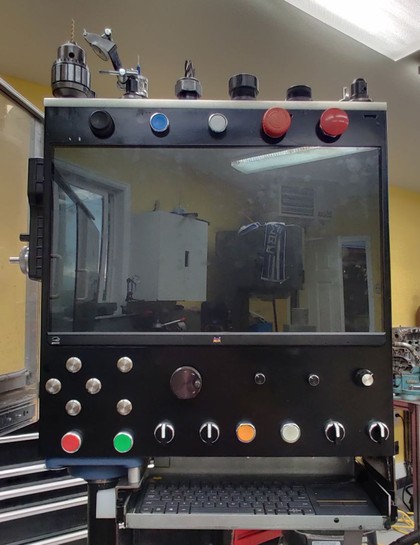
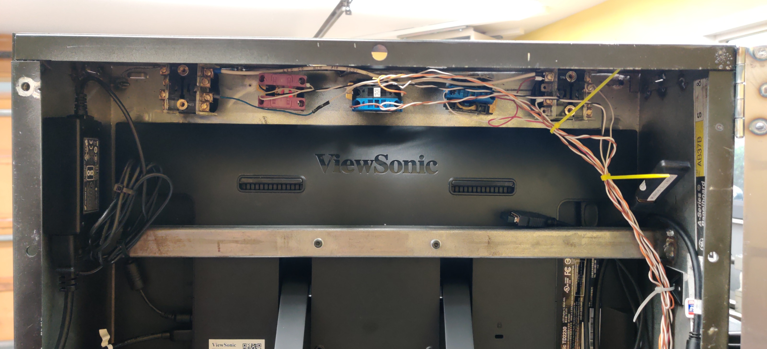
The monitor is a ViewSonic TD2230-R 22" capacitive touch screen. It's crazy how cheaply you can get monitors for now - this one was only $99 shipped. I had been running the machine on 2.7 with axis for years, so I was excited to upgrade to Probe Basic with a touch screen.
Below the monitor I have jog buttons for X, Y and Z, with a potentiometer for setting jog speed. I also have a .01"/.001"/.0001" X/Y/Z step MPG encoder. I had been using an XHC-HB04 bluetooth pendant to do most control, and I used the keyboard for jogging. Physical buttons made a huge difference to the smoothness of control. Moving the machine around is much easier and more accurate now.
The yellow button issues a MDI for safe Z height, the white button is for the spindle brake and the far right 3 way selector is for mist ON/OFF/Auto. I haven't yet decided what to do with the other selector switch - I was thinking about using it for a spindle REV/OFF/FOR, but I'm not sure how I'd like to implement that yet. I added a slide out tray for a keyboard. I also milled a piece of 1/2" HDPE to accept twelve, 30 taper tools and mounted that to the top of the pendant.
I used Omron A22NZ buttons for most of the controls. The jog buttons are 19mm arcade style buttons from Amazon. I didn't debounce any of the buttons and haven't had any problems with errant signals.
The whole assembly can swivel at the base of the machine and at the panel. I turned the OD of some SCH10 1.5" pipe to slip into a HDPE tube. I welded a fixture to the base of the mill to hold the panel arm.
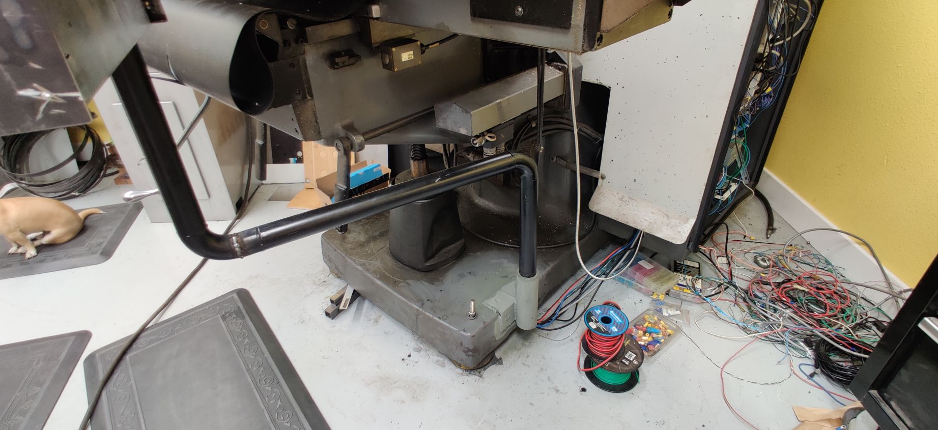
It does wobble a bit when typing or making cuts, but it's tolerable. All the wires run through the pipe and I can easily position the control panel to stay in a convenient position.
Attachments:
Please Log in or Create an account to join the conversation.
- arvidb
-

- Offline
- Platinum Member
-

- Posts: 459
- Thank you received: 158
Since 2.6kW is equivalent to ~3.5HP, I thought I'd have more power than the original setup. However, I forgot about accounting for the gear reduction necessary to spin the spindle at the desired speed of 7000RPM. Luckily, I was able to send the 2.6kW servo back in exchange for a 3.8kW model (130st-M15025-BZ).
My main goal in the conversion was to keep costs as low as possible, so I retained the 23 spline timing belt gear from the original assembly. This allowed me to get rid of almost every drive component from the original vari-speed unit, greatly reducing the complexity of the head. I used a 64 tooth pulley on the servo motor for a ratio of 2.78:1, giving me a top speed of 6956RPM. If my math is right, I have an effective 1.83HP at the spindle and given the original motor's 1725RPM and 2HP rating, I should have more power above 1600RPM.
Maybe I'm misunderstanding what you've written, but in case I'm not:
Gearing doesn't modify the power available (except for some losses). So if you have 3.8 kW before the gearing, you'll have ~3.8 kW after the gearing as well. However, for AC servos (and DC motors) power output is proportional to speed (that is, these motors have constant torque: power is torque×speed). So nominal power is at nominal speed; at half that speed you have half the power etc.
So with your fixed 64/23 gearing and 3.8 kW motor, you will have ~3.0 kW available at 5500 rev/min and about 0.87 kW at 1600 rev/min. The 2 hp point is ~2730 rev/min [(64/23×2500)×(2hp/3.8kW)].
If the original vari-speed was a continous ratio gear, the nice thing with that is that since you always run the motor at full speed you also always get the full power out, at all speeds.
Please Log in or Create an account to join the conversation.
- tightmopedman9
- Offline
- Senior Member
-
- Posts: 73
- Thank you received: 7
Since torque is F * D, it makes sense that as gearing changes, torque changes. What I'm confused about, is what is the significant rating as far as the cutter is concerned?
I thought the constant torque of an AC servo would be preferable for a spindle, as torque output doesn't drop as a function of cutter speed. With a constant speed motor and vari-speed drive, cutting power drops as cutter speed increases, no?
Not that any of this matters now, as I already have the new drive set up and won't ever be switching back. I've noticed that with the AC servo, there is no spindle speed bogging during heavy cuts, which there was with the original 2hp and vari-speed drive.
Please Log in or Create an account to join the conversation.
- arvidb
-
- Offline
- Platinum Member
-
- Posts: 459
- Thank you received: 158
Larger, slower tools often require more torque. So you ideally want constant power, not constant torque - so gearing is ideal for a spindle, to get the most out of the motor. Gearing is noisy, heavy, expensive and difficult to control automatically though.I thought the constant torque of an AC servo would be preferable for a spindle, as torque output doesn't drop as a function of cutter speed.
")
With gearing power stays constant. Say you gear up 2x, then you have twice the speed and half the torque. Since power = speed × torque, power stays the same.With a constant speed motor and vari-speed drive, cutting power drops as cutter speed increases, no?
I think using a large motor is the way most modern, professional CNC machines solve this problem. Gearing is just too cumbersome on an automatic machine. And you have more power available now at the HSM spindle speeds you normally use, so that's great! You might have less power available than before if you want to run, say, a large flycutter though.Not that any of this matters now, as I already have the new drive set up and won't ever be switching back. I've noticed that with the AC servo, there is no spindle speed bogging during heavy cuts, which there was with the original 2hp and vari-speed drive.
Please Log in or Create an account to join the conversation.