I had this crazy idea - Lets build a shock dyno with Linuxcnc
- rodw
-
 Topic Author
- Offline
- Platinum Member
-

Less
More
- Posts: 11948
- Thank you received: 4068
20 Dec 2019 13:18 #152939
by rodw
I had this crazy idea - Lets build a shock dyno with Linuxcnc was created by rodw
Like I said, this is a crazy Idea but I found this page about building a Shock Dyno. www.sportdevices.com/shock-absorber.php


They even have a zip file with some drawings on that page.
Now I know nothing about shock dynos but knowing as much about plasma cutting did not stop me from building a kick ass plasma cutter!
The only relevant experience I have is making a drawbar dynanometer to test the pull on tractor drawbars back in about 1982!
So when I looked at the price of the dyno electronics kit I figured it would be pretty easy getting the data into a PC with Linuxcnc. I just don't know how to get it out yet.
So I figured with some gear like this, it would not be too hard.
1. Mesa Card
2. A Thcad-10
3. A load cell
4. A load Cell 0-10v interface.
5. 3 phase motor with a gearbox reduction drive
6. A VFD controlled by Modbus
7 A linear scale
8. a HGR25 rail and carriage for a scotch yoke (They are good for about 7 tonne static load from what I could see).
9. a custom Linuxcnc component to decode and present force and velocity data and graphs to some unknown interface.
So before I knew it, I am about $2k into the project with orders in place for:
1. Unused/surplus Mitsubishi 5.5 kW 3 phase motor with 5:1 reduction gear box (300 rpm) About 180 kg of gear I'm told
2. A VFD for said motor with a Modbus Interface
3. A $10 RS232 to RS485 interface for said Modbus interface
4. 2 load cells becasue I have no Idea what size to use (1 tonne and 2 tonne)
5. 2v to 10v Load cell interface for THCAD-10
6. PC I have
7 THCAD-10 I have
8 Mesa 7i76e and 7i96 I have (I think I will need another encoder input though)
We are talking 4WD shocks here, not the racing variety so want a good length throw.
The swing over my gap bed on the lathe is 400 mm but maybe I can borrow a lathe with a bigger chuck if I want to go bigger. 18" would be nice.
I drew up a flywheel with a heap of holes that I would get laser cut ready to be tapped and I'm beginning to wonder if I need to worry about being able to chuck it up at all. Maybe I can just bolt it to a boss so I can go bigger. Some serious thinking to do there!
Anyway, if anybody actually knows anything about shock Dynos, it would be good to hear your thoughts. It will take a couple of weeks before stuff will arrive over the Christmas break.. In the meantime, I'm sure there is plenty of design time I can find.
I'd also like to know if you could get 2 encoder inputs onto a 7i76e or 7i96. I think I'd use the 7i76e if possible as the analog inputs might be useful.
Also ideas on generating reports and graphs. Could I cheat and use the X & Y axes and plot something that way simply by scaling the axis to suit? But I'd need to save and print the result for future reference.
Cheers guys. Help me bring this crazy idea into reality!
Please Log in or Create an account to join the conversation.
- tommylight
-

- Offline
- Moderator
-

Less
More
- Posts: 21625
- Thank you received: 7383
20 Dec 2019 16:54 #152957
by tommylight
Replied by tommylight on topic I had this crazy idea - Lets build a shock dyno with Linuxcnc
Hmmm interesting !
The following user(s) said Thank You: rodw
Please Log in or Create an account to join the conversation.
- sprintertrd
- Offline
- Junior Member
-

Less
More
- Posts: 28
- Thank you received: 7
21 Dec 2019 05:19 - 21 Dec 2019 05:27 #152985
by sprintertrd
Replied by sprintertrd on topic I had this crazy idea - Lets build a shock dyno with Linuxcnc
Hi Rod,
You will need to plot Shock shaft velocity Vs Load and then you will have a graph that looks like a V_g_na for bump and rebound based on the valving in the shock.
There are plenty of books on the subject. Many years ago I and some others were guinea pigs for his race engineering course created by Claude Rouelle (Optimum G ) ( Never had to use it in my position )
You could also download MoTeC I2 that may have sample data logging from a race car with shock data. Basically they log shock shaft position and then generate velocities from that.
Also the higher sample rate the better your data will be. I seem to remember something like 1000 samples/s and higher.
Fleebay has cheep strain gauge amps for your load cells.
Last edit: 21 Dec 2019 05:27 by sprintertrd.
The following user(s) said Thank You: rodw
Please Log in or Create an account to join the conversation.
- rodw
-
Topic Author
- Offline
- Platinum Member
-
Less
More
- Posts: 11948
- Thank you received: 4068
21 Dec 2019 10:01 #152990
by rodw
Replied by rodw on topic I had this crazy idea - Lets build a shock dyno with Linuxcnc
Sprinter, thanks. Thats pretty much what I had in mind. Using a THCAD-10 with a 0-10 volt amp will allow very precise measurement of voltage to calculate load 1000 times per second.
A linear scale would return shaft position and by measuring the distance travelled per servo thread cycle, we can calculate velocity.
So all of that is pretty simple to do in a custom component. At a basic level, sampler and halsampler would allow the data to be logged for eventual analysis and graphing in a spreadsheet. So essentially, Linuxcnc has everything I need to read the data.
Please Log in or Create an account to join the conversation.
- rodw
-
Topic Author
- Offline
- Platinum Member
-
Less
More
- Posts: 11948
- Thank you received: 4068
06 Jan 2020 10:46 #154138
by rodw
Replied by rodw on topic I had this crazy idea - Lets build a shock dyno with Linuxcnc
Well, I am still waiting for stuff to arrive due to people being on holidays over the Christmas break. But this obscenely large Mitsubishi 5:1 geared motor has arrived, all 124 kg of it. Yup thats a 55mm shaft on that puppy! As you can see, its brand new and was in the store at the GM Holden plant when it was closed.
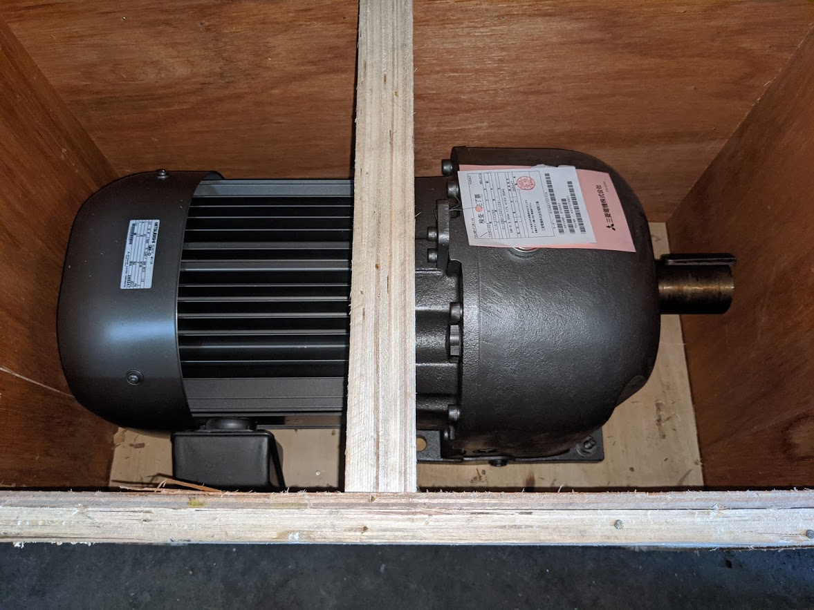
The VFD is still on its way as are the load cells.
I found a bit of time to design some parts. The plan is to get some parts laser cut out of 16mm steel and use a linear rail for the scotch yoke.
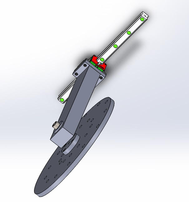
I nearly bought some HGR25 rails for this but decided I better wait and make sure. I'm glad I did because I had to upgrade to HGR30 and a wide carriage to be able to bolt things together.
So the pin that attaches the crank to the flywheel is 20mm diameter and is secured by a 16mm bolt. I think I need to rework this a bit but its a start. The cap needed a bit of a scallop out of it to gain clearance for a couple of pin positions at the short end of the throw. The larger flywheel is keyed to the shaft and the cap is secured to the M10 bolt in the centre of the shaft and the 4 bolts are there to stop the flywheel from sliding backwards. The throw is determined by which hole the pin is mounted to (there are a lot of holes to tap!)
The bearing is a simple deep groove thrust bearing 20mm ID and 40mm OD. It cost all of $12 and is good for about 2300 kg of thrust which should be enough!. Its not shown in the render but I've added a grease nipple to the bottom face of the crank.
And the part I'm not looking forward to is sorting out the 16mm wide keyway. I thought this would be easy but I found my broaches only go up to a 30mm shaft and 10mm wide keyway. I think we will try to get the keyway cut in with the laser cutter and file it to size unless someone has an idea. I did ask a guy at the machine shop next door. They do some pretty big stuff for cranes and even he baulked at a 16mm keyway!
So the minimum movement will be around 75mm and the maximum about 400mm and the throw can be selected in 12.5mm increments. I think will fit in my lathe if I remove the bed.
Sorry about the model being upside down but the linear rail will be fixed to a cross member that slides up and down on two 30mm uprights. I will use 30mm linear bearings for this slider. In the centre of this cross member there will be a 30mm post that slides up through a linear bearing fixed higher up. The advantage of the scotch yoke design is that the motion becomes perfectly sinusoidal which is not the case if a crank is used.
I'm pretty happy that the bulk of the thinking is done and we've made a significant start on the design so it will all come together.
The VFD is still on its way as are the load cells.
I found a bit of time to design some parts. The plan is to get some parts laser cut out of 16mm steel and use a linear rail for the scotch yoke.
I nearly bought some HGR25 rails for this but decided I better wait and make sure. I'm glad I did because I had to upgrade to HGR30 and a wide carriage to be able to bolt things together.
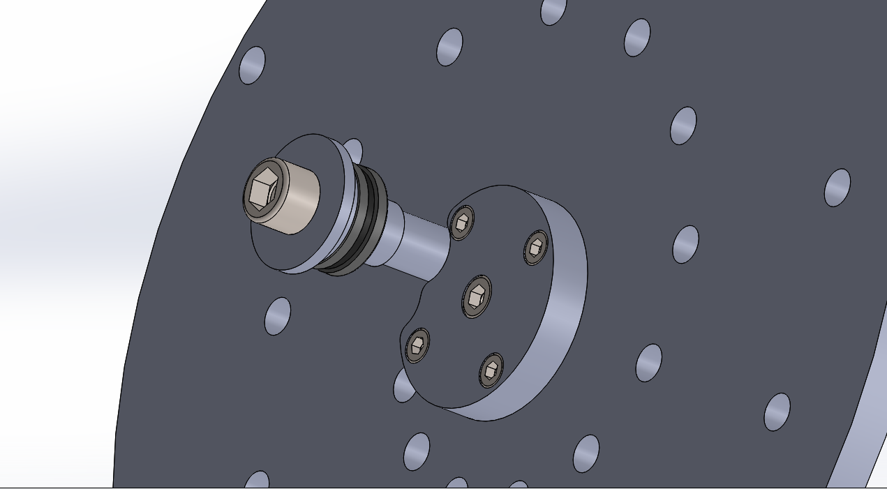
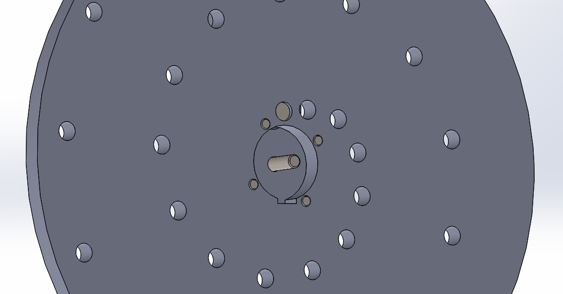
So the pin that attaches the crank to the flywheel is 20mm diameter and is secured by a 16mm bolt. I think I need to rework this a bit but its a start. The cap needed a bit of a scallop out of it to gain clearance for a couple of pin positions at the short end of the throw. The larger flywheel is keyed to the shaft and the cap is secured to the M10 bolt in the centre of the shaft and the 4 bolts are there to stop the flywheel from sliding backwards. The throw is determined by which hole the pin is mounted to (there are a lot of holes to tap!)
The bearing is a simple deep groove thrust bearing 20mm ID and 40mm OD. It cost all of $12 and is good for about 2300 kg of thrust which should be enough!. Its not shown in the render but I've added a grease nipple to the bottom face of the crank.
And the part I'm not looking forward to is sorting out the 16mm wide keyway. I thought this would be easy but I found my broaches only go up to a 30mm shaft and 10mm wide keyway. I think we will try to get the keyway cut in with the laser cutter and file it to size unless someone has an idea. I did ask a guy at the machine shop next door. They do some pretty big stuff for cranes and even he baulked at a 16mm keyway!
So the minimum movement will be around 75mm and the maximum about 400mm and the throw can be selected in 12.5mm increments. I think will fit in my lathe if I remove the bed.
Sorry about the model being upside down but the linear rail will be fixed to a cross member that slides up and down on two 30mm uprights. I will use 30mm linear bearings for this slider. In the centre of this cross member there will be a 30mm post that slides up through a linear bearing fixed higher up. The advantage of the scotch yoke design is that the motion becomes perfectly sinusoidal which is not the case if a crank is used.
I'm pretty happy that the bulk of the thinking is done and we've made a significant start on the design so it will all come together.
Attachments:
Please Log in or Create an account to join the conversation.
- rodw
-
Topic Author
- Offline
- Platinum Member
-
Less
More
- Posts: 11948
- Thank you received: 4068
07 Jan 2020 07:13 #154200
by rodw
Replied by rodw on topic I had this crazy idea - Lets build a shock dyno with Linuxcnc
Well the design is slowly taking shape. I had no idea how big this thing was going to be. Its a metre long to accommodate the VFD
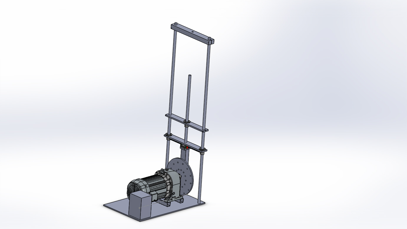
The uprights are 2 metres high and I don't think that will be tall enough,
The uprights are 2 metres high and I don't think that will be tall enough,
Please Log in or Create an account to join the conversation.
- tommylight
-
- Offline
- Moderator
-
Less
More
- Posts: 21625
- Thank you received: 7383
07 Jan 2020 12:40 #154209
by tommylight
Replied by tommylight on topic I had this crazy idea - Lets build a shock dyno with Linuxcnc
It looks like you will be changing the amplitude by moving the pin on the flywheel, so that would mean having a set amplitude to test, if i remember correctly from servicing some car checking equipment they have a changing amplitude, they start low and gradually raise the amplitude then it lowers again while the frequency is changed at the same time. Just a thought, since you are much more experienced in this field, i will now shut up.
")
Please Log in or Create an account to join the conversation.
- rodw
-
Topic Author
- Offline
- Platinum Member
-
Less
More
- Posts: 11948
- Thank you received: 4068
07 Jan 2020 12:52 - 07 Jan 2020 12:53 #154210
by rodw
Replied by rodw on topic I had this crazy idea - Lets build a shock dyno with Linuxcnc
Fogot to mention, the VFD and Loadcells turned up today.
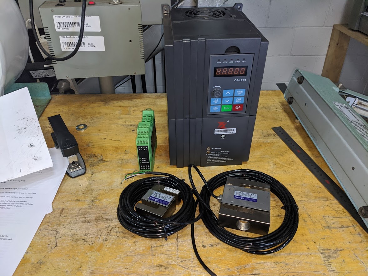
I bought 2 load cells. one with 1 tonne capacity and the other 2.5 tonnes. I'm not sure what I will use yet. The 2.5 t one looks like it uses a M20 bolt, the smaller one uses a M12.
The Din Rail module will output a 0-5 volt signal which I plan to read with a THCAD-5
I bought 2 load cells. one with 1 tonne capacity and the other 2.5 tonnes. I'm not sure what I will use yet. The 2.5 t one looks like it uses a M20 bolt, the smaller one uses a M12.
The Din Rail module will output a 0-5 volt signal which I plan to read with a THCAD-5
Last edit: 07 Jan 2020 12:53 by rodw.
Please Log in or Create an account to join the conversation.
- chimeno
- Offline
- Elite Member
-

Less
More
- Posts: 295
- Thank you received: 125
07 Jan 2020 20:10 - 07 Jan 2020 20:22 #154248
by chimeno
Replied by chimeno on topic I had this crazy idea - Lets build a shock dyno with Linuxcnc
Hi Rodw, what a cool project! I will be watching the progress!
regards
Chimeno
regards
Chimeno
Last edit: 07 Jan 2020 20:22 by chimeno. Reason: Edit
Please Log in or Create an account to join the conversation.
- rodw
-
Topic Author
- Offline
- Platinum Member
-
Less
More
- Posts: 11948
- Thank you received: 4068
07 Jan 2020 20:47 #154254
by rodw
In all honesty, tommy I know nothing about this subject. But yes you are right, changing the location of the lower crank pin will allow the travel (Amplitude) to vary from about 75mm to 400m. I see some use a shaft encoder to monitor position but I had in mind to use a linear scale for the encoder and that should resolve to an exact position. Hopefully, the machine can learn the travel without needing to change a setting every time you change the diameter of the crank (which is what you would have to do if you were using a rotary shaft encoder).
Replied by rodw on topic I had this crazy idea - Lets build a shock dyno with Linuxcnc
It looks like you will be changing the amplitude by moving the pin on the flywheel, so that would mean having a set amplitude to test, if i remember correctly from servicing some car checking equipment they have a changing amplitude, they start low and gradually raise the amplitude then it lowers again while the frequency is changed at the same time. Just a thought, since you are much more experienced in this field, i will now shut up.
In all honesty, tommy I know nothing about this subject. But yes you are right, changing the location of the lower crank pin will allow the travel (Amplitude) to vary from about 75mm to 400m. I see some use a shaft encoder to monitor position but I had in mind to use a linear scale for the encoder and that should resolve to an exact position. Hopefully, the machine can learn the travel without needing to change a setting every time you change the diameter of the crank (which is what you would have to do if you were using a rotary shaft encoder).
Please Log in or Create an account to join the conversation.
Time to create page: 0.273 seconds