I had this crazy idea - Lets build a shock dyno with Linuxcnc
- rodw
-
 Topic Author
- Online
- Platinum Member
-

- Posts: 12007
- Thank you received: 4089
I don't know how to offset the stroke servo while its rotating from a Linuxcnc standpoint. I need some guidance as I would hate build this and not be able to control it!
We have restrictions due to the length of the motor shaft (80mm) when the taper lock takes up 40mm.
The thinnest 55mm thru shaft rotary encoder I could find was 30mm so there might not be enough room to add it and a timing belt pulley. So that means we probably need to make our own slotted disc encoder wheel. That would be easy to get laser cut but I'd need guidance on sensor selection and how to put it together (and get an index signal).
Some guidance in relation servo motor holding torque requirements to move the bigend assembly is needed but that can wait till we sort out the bevel gear ratios..
And my questionable skill as a machinist to hold the tolerances required for press fit parts! I'll work that out I guess.
But I did get as far as working out how to animate my current assembly so I could check clearance on the scotch yoke and I have to move the posts a few mm further apart to get clearance for the grease nipple on the carriage!
Please Log in or Create an account to join the conversation.
- andypugh
-

- Offline
- Moderator
-

- Posts: 19875
- Thank you received: 4642
We have restrictions due to the length of the motor shaft (80mm) when the taper lock takes up 40mm.
The thinnest 55mm thru shaft rotary encoder I could find was 30mm so there might not be enough room to add it and a timing belt pulley.
Could you mount an encoder on the back of the motor? The gear ratio is fixed.
Alternatively, a second toothed belt to a shaft encoder geared 1:1 should be fairly easy to squeeze in.
Drill a circle of holes in the back of your crank?
Please Log in or Create an account to join the conversation.
- rodw
-
Topic Author
- Online
- Platinum Member
-
- Posts: 12007
- Thank you received: 4089
Please Log in or Create an account to join the conversation.
- Clive S
- Offline
- Platinum Member
-
- Posts: 2204
- Thank you received: 486
So that means we probably need to make our own slotted disc encoder wheel. That would be easy to get laser cut but I'd need guidance on sensor selection and how to put it together (and get an index signal).
Would something like this work. I have had this reading to 4000rpm with a PPort and a good BOB
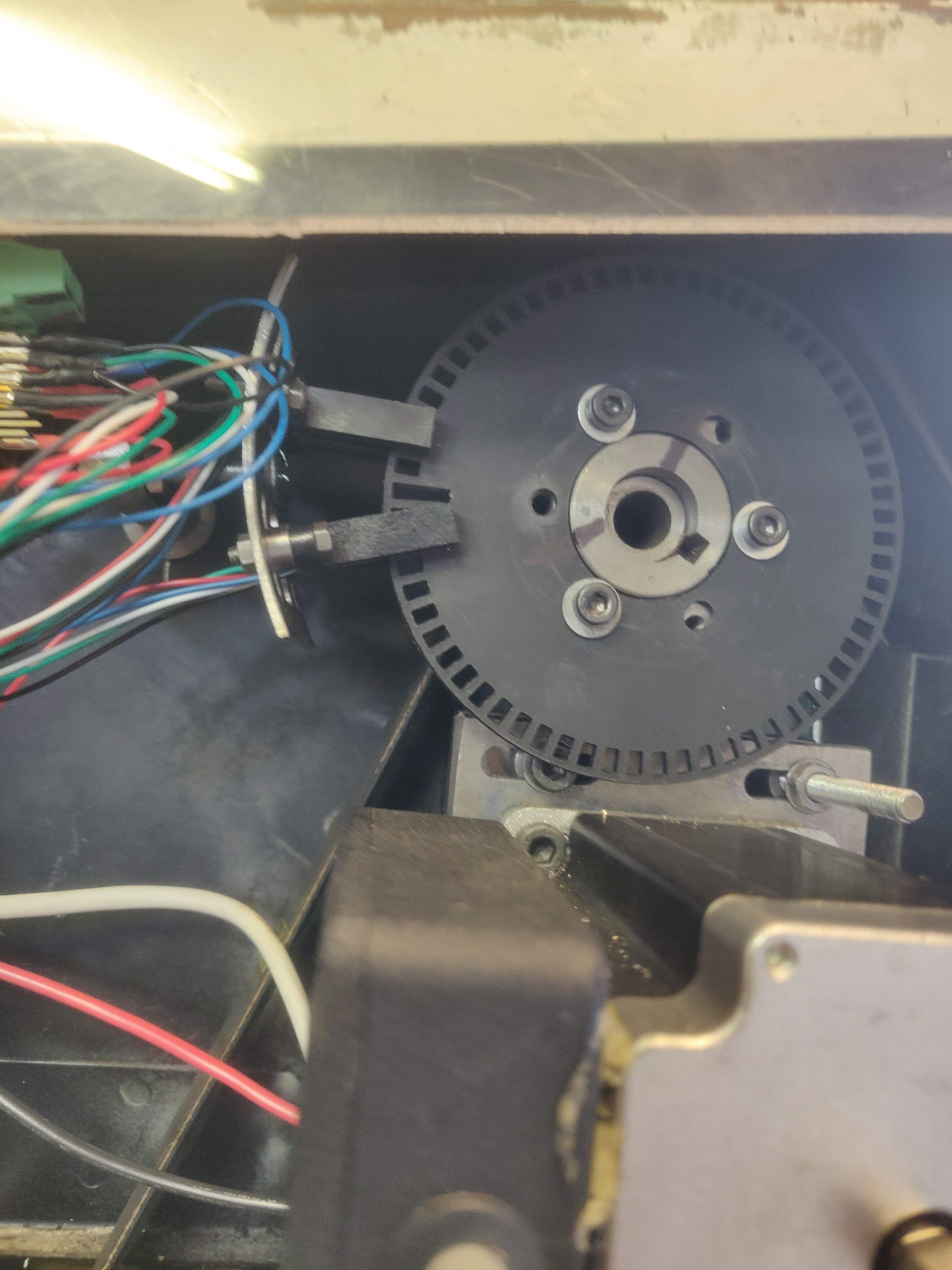
Attachments:
Please Log in or Create an account to join the conversation.
- rodw
-
Topic Author
- Online
- Platinum Member
-
- Posts: 12007
- Thank you received: 4089
Please Log in or Create an account to join the conversation.
- Clive S
- Offline
- Platinum Member
-
- Posts: 2204
- Thank you received: 486
Clive, thanks. Is the second sensor for the index slot ?
Yes the one with the longest slot is he index you could add another sensor to make it full quadrature which I have done on my lathe.
This disc is just plastic laser cut but I've also made them on the mill with a small cutter.
There are 64 slots in that disc. The senses are about £3 each from radio spares
Please Log in or Create an account to join the conversation.
- rodw
-
Topic Author
- Online
- Platinum Member
-
- Posts: 12007
- Thank you received: 4089
And for the record, the rear shaft is hidden behind the back cover so I need to have a look at it too.
Please Log in or Create an account to join the conversation.
- andypugh
-
- Offline
- Moderator
-
- Posts: 19875
- Thank you received: 4642
Please Log in or Create an account to join the conversation.
- Clive S
- Offline
- Platinum Member
-
- Posts: 2204
- Thank you received: 486
Thanks Clive. The second sensor needs to be aligned carefully I heard. How is it done?
You need one index (long slot) and one sensor for the A channel. That will give you syncro motion in one direction.
ie threading.
If you want to be able to know which direction the motor is running then you need the second sensor for the B channel. ie for rigid tapping. It does this with the phase difference between them. one is leading and the other lagging. I think they need to be 90' apart. I set this up with a scope by just moving one sensor around the disc. Halscope would probably do this.
Please Log in or Create an account to join the conversation.
- andypugh
-
- Offline
- Moderator
-
- Posts: 19875
- Thank you received: 4642
If you want to be able to know which direction the motor is running then you need the second sensor for the B channel.
For the shock dyno you might well want full quadrature, as the crank might reverse when the machine is turned off, losing the phase relationship with the adjuster.
Please Log in or Create an account to join the conversation.