I had this crazy idea - Lets build a shock dyno with Linuxcnc
- tommylight
-

- Offline
- Moderator
-

- Posts: 21625
- Thank you received: 7383
Thinking that if that is for the assembly, one side of it must be free to travel, normally wheels get detached from ground when the car is jumping !
Please Log in or Create an account to join the conversation.
- rodw
-
 Topic Author
- Offline
- Platinum Member
-

- Posts: 11948
- Thank you received: 4068
Please Log in or Create an account to join the conversation.
- andypugh
-

- Offline
- Moderator
-
- Posts: 19861
- Thank you received: 4636
In a previous job I ran (and built) fatigue testing machines. And in another previous job I designed motor and brake testing dynos.
So I think this should be pretty easy with LinuxCNC, but you might want to think about how to vary the stroke. I am seeing steam-engine valvegear as a possible inspiration.
Though I do have another idea that I once thought of patenting. Have you ever used a shaper? Are you familiar with the stroke adjustment?
Please Log in or Create an account to join the conversation.
- rodw
-
Topic Author
- Offline
- Platinum Member
-
- Posts: 11948
- Thank you received: 4068

The concern I had was becasue of the size of the shaft (55mm dia), the minimum stroke I can get is 75mm. It would be better If I could get that right down. I did think of mounting this plate to a hub so the stroke adjusting holes could extend further into the centre but we were worried about the shear forces on the hub mounting bolts. You will know more about the maths but we have a 5.5 kW motor with a 5:1 reduction gearbox with a 200mm radius from the centre of the shaft. So how many hub bolts and what diameter are they assuming a 8.8 grade bolt?

Allowing for some losses I think thats about 25 kN max. The shear force for a M12 bolt is 31kN so surely 4-5 bolts would hold it?
The other thing I wondered is could I just reverse the motor under CNC control to get short strokes. I guess it would not be sinusoidal and there is some backlash in the motor's gearbox but then again potholes are not perfectly symmetric.
I am vaguely familiar with a shaper and a mate has an old one. I might look at it more closely. In fact before he acquired it, he designed one in CAD and said he wished he had thought of the linear rail!
If you have other ideas about adjusting the stroke, I am all ears! It would be cool if it could be under CNC control!
Attachments:
Please Log in or Create an account to join the conversation.
- andypugh
-
- Offline
- Moderator
-
- Posts: 19861
- Thank you received: 4636
www.bearingboys.co.uk/?catid=2596&displa...mm&att3=&att4=&att5=
Then mate that to an off-the-shelf flange:
www.bearingboys.co.uk/Bolt-On-Hubs/BF25-...--Taper-Bush-91123-p
And then stop worrying about the bolt size, as you are committed to 6 x M10 on a 155mm PCD.
Or use a weld-in hub: www.bearingboys.co.uk/Weld-On-Hubs/WH252...Bore-WH-Type-91107-p
But, assuming a 1500 rpm motor, 5:1 reduction is 300rpm or 31 rad/sec
5.5kW @ 31 rad/sec is 175 Nm torque.
Shear strength of a single M6 grade 8.8 bolt is 7.7kN. So one M6 at a radius of 22mm would take the torque. The 6 x M10 on the off-the-shelf flange are good to 10,000 Nm.
(sanity check: the key in the 55mm shaft is considered adequate for the rated output torque)
How about this design for infinitely-variable stroke using a weld-in taperlock hub and plasma-cut plate parts?
a360.co/2scAC2g
Please Log in or Create an account to join the conversation.
- rodw
-
Topic Author
- Offline
- Platinum Member
-
- Posts: 11948
- Thank you received: 4068
With your design, would my lower pin just bolt into a backing plate in the slot so it clamps in the desired position? Thats how I'm reading it.
I like it! Plus the stroke is no longer limited to the throw on my lathe.
Please Log in or Create an account to join the conversation.
- andypugh
-
- Offline
- Moderator
-
- Posts: 19861
- Thank you received: 4636
Andy, some very cool ideas thanks. I did not know about taper locks. They tell us nothing in the colonies.
I am sure you can source them locally. They are a rather nice way to mount things to motor shafts.
In fact: www.iw.net.au/product/384-taperlock-bush...-bore?categoryId=634
Yes, that's the idea. You could evan add an adjusting screw for precision. (the slot only need to be on one side, incidentally, and would balance better)With your design, would my lower pin just bolt into a backing plate in the slot so it clamps in the desired position?
I like it! Plus the stroke is no longer limited to the throw on my lathe.
How much stroke do you really need?
Please Log in or Create an account to join the conversation.
- rodw
-
Topic Author
- Offline
- Platinum Member
-
- Posts: 11948
- Thank you received: 4068
As far as stroke, I'm not 100% sure. A lot of the race car shock dynos only offer 2-3" of stroke and for 4WD's I just had a look at a catalog and 300mm would cover most shocks. But then there are long travel offroad competition shocks that have a lot more travel. Some of these have triple bypasses etc so you'd need to cover all the valves I think. YOu can always adjust the top mount to exercise a different section of the shock anyway.
So the 400mm stroke (200 mm radius) I have now is probably OK for mere mortals.
And yes, I was thinking of how to add some precision adjustment. But if I add the linear scale HAL can measure the top and bottom of the stroke for me with a custom component. Then you could check the stroke precisely.
Very helpful advice which I really appreciate Andy.
Please Log in or Create an account to join the conversation.
- andypugh
-
- Offline
- Moderator
-
- Posts: 19861
- Thank you received: 4636
The idea is to have a small shaft with a bevel gear on the end running down the middle of the main drive shaft. That engages with a second bevel on the stroke-adjusting screw.
The cunning bit is that this is operated by a servo which is kept in (PID) locked phase to the main drive shaft. Except when you want to adjust the stroke, at which point an offset is applied.
But I can't see a way for that to work _except_ coaxially down the main drive shaft.
There is a way to do this mechanically, my dad's horizontal boring machine has exactly that arrangement, you can feed-in radial moves while the chuck is rotating. But, again, it goes in from the back.
Please Log in or Create an account to join the conversation.
- rodw
-
Topic Author
- Offline
- Platinum Member
-
- Posts: 11948
- Thank you received: 4068
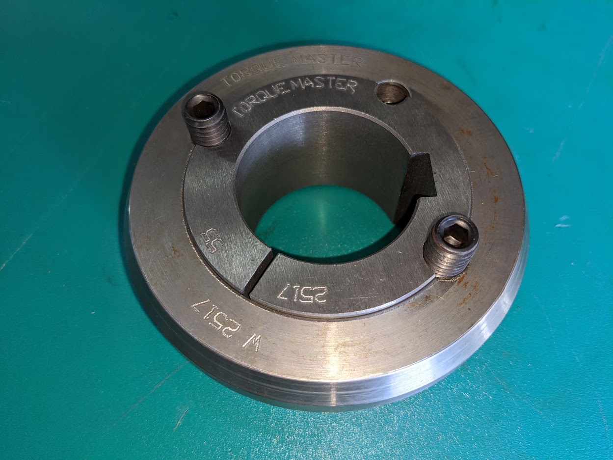
Went to my bearing shop and they had one on the shelf! Cost me AUD $13.12 for the taper bush and $22.85 for the weld in hub excluding our 10% GST.
I get what your cunning idea is.
Because we are essentially building a box for the adjusting mechanism mounted to the front of the shaft, the adjusting shaft could enter from the front. I have a couple of tiny Yaskawa servos here and one of them might be perfect for the job. They are good for 2000 or 3000 rpm so will easilly be able to keep up. Just that they need 100 volt AC power so I'd have to factor in a power supply for them. But I would have to incorporate an encoder on the shaft so you have something to phase lock to. This might actually make for a cleaner build becasue if we knew the arm length via feedback from your mechanism, we could calculate the distance traveled at any given point on the radius. You'd need to be able to build in some sort of lock to ensure that the shock travel was not exceeded which probably would not be pretty!
Please Log in or Create an account to join the conversation.