Hurco Hawk 5M Retrofit w/ existing motors
- biqut2
- Offline
- Premium Member
-

Less
More
- Posts: 97
- Thank you received: 5
15 Apr 2018 01:07 #109031
by biqut2
Replied by biqut2 on topic Hurco Hawk 5M Retrofit w/ existing motors
The servo rotates smoothly on battery power. Is there a real quick "sanity check" I can perform to make sure I'm communicating with the 7i77 as well as the 5i25?
Please Log in or Create an account to join the conversation.
- PCW
-

- Offline
- Moderator
-

Less
More
- Posts: 17997
- Thank you received: 5284
15 Apr 2018 01:23 #109032
by PCW
Replied by PCW on topic Hurco Hawk 5M Retrofit w/ existing motors
if you set an output voltage with the open loop test you should be able to read that voltage on the 7I77 outputs
Please Log in or Create an account to join the conversation.
- biqut2
- Offline
- Premium Member
-
Less
More
- Posts: 97
- Thank you received: 5
15 Apr 2018 01:27 #109033
by biqut2
Replied by biqut2 on topic Hurco Hawk 5M Retrofit w/ existing motors
The open loop test doesn't seem to work, can this be done from the command line?
Please Log in or Create an account to join the conversation.
- PCW
-
- Offline
- Moderator
-
Less
More
- Posts: 17997
- Thank you received: 5284
15 Apr 2018 01:31 #109034
by PCW
Replied by PCW on topic Hurco Hawk 5M Retrofit w/ existing motors
Can you launch the pncconf created linuxcnc hal file?
Please Log in or Create an account to join the conversation.
- biqut2
- Offline
- Premium Member
-
Less
More
- Posts: 97
- Thank you received: 5
15 Apr 2018 01:35 #109035
by biqut2
Replied by biqut2 on topic Hurco Hawk 5M Retrofit w/ existing motors
No, it gives me an error about maxscale no being available or something like that. I just noticed this in the 7i77manual:
In normal operation CR1 through CR7 must always be on. At power-up, CR15
should be off and CR16 on. The red LED CR16 indicates a watchdog fault, which is
expected before host communications are established. Once running, CR15 should blink
at about 1 Hz for a 1 KHz update rate, and CR16 should be off. Note: CR15 and CR16 are
only present in revision B or greater 7I77 cards.
CR1 isn't lit on my card.
I have the jumpers set to use the 5v from the host card. Do you think I need to hook up an external 5vcd supply> could that be the problem?
Please Log in or Create an account to join the conversation.
- PCW
-
- Offline
- Moderator
-
Less
More
- Posts: 17997
- Thank you received: 5284
15 Apr 2018 01:42 - 15 Apr 2018 01:46 #109037
by PCW
Replied by PCW on topic Hurco Hawk 5M Retrofit w/ existing motors
Yes, as the 7I77 manual suggests, you can do simple tests with 5V from the FPGA card with a 7I77 but its almost guaranteed not to work well if you attempt to power a number of older (and high power consumption) encoders.
However I would expect some power drop in this case but I still would expect CR1 to be on (since it will light dimly even at ~3V) So you may have a jumpering error or a external short on the encoder wiring so I would check this carefully before proceeding
Jumpering
5V from 5I25
5I25 W2 up
7I77 W5 left
5V from 7I77 TB1
5I25 W2 down
7I77 W5 right
Last edit: 15 Apr 2018 01:46 by PCW.
Please Log in or Create an account to join the conversation.
- biqut2
- Offline
- Premium Member
-
Less
More
- Posts: 97
- Thank you received: 5
15 Apr 2018 01:54 - 15 Apr 2018 01:55 #109038
by biqut2
Replied by biqut2 on topic Hurco Hawk 5M Retrofit w/ existing motors
Right again, as usual, I had W1 up and W2 down, after witching W2 to up I can now get encoder reading through the open loop test, I can also very the correct voltages and switching on the output pins. Still no movement though, I may have forgotten to check one of the limit switches. It'll take just a couple of minutes to recheck that wiring. I can't thank you enough for all the help you've been thus far. I feel like I've very close to having this setup all hashed out.
Last edit: 15 Apr 2018 01:55 by biqut2. Reason: typo
Please Log in or Create an account to join the conversation.
- biqut2
- Offline
- Premium Member
-
Less
More
- Posts: 97
- Thank you received: 5
15 Apr 2018 02:14 #109040
by biqut2
Replied by biqut2 on topic Hurco Hawk 5M Retrofit w/ existing motors
I fixed the limit switch, I had it wired NO and it needed to be NC. It's working now!
Please Log in or Create an account to join the conversation.
- biqut2
- Offline
- Premium Member
-
Less
More
- Posts: 97
- Thank you received: 5
16 Apr 2018 01:27 #109109
by biqut2
Replied by biqut2 on topic Hurco Hawk 5M Retrofit w/ existing motors
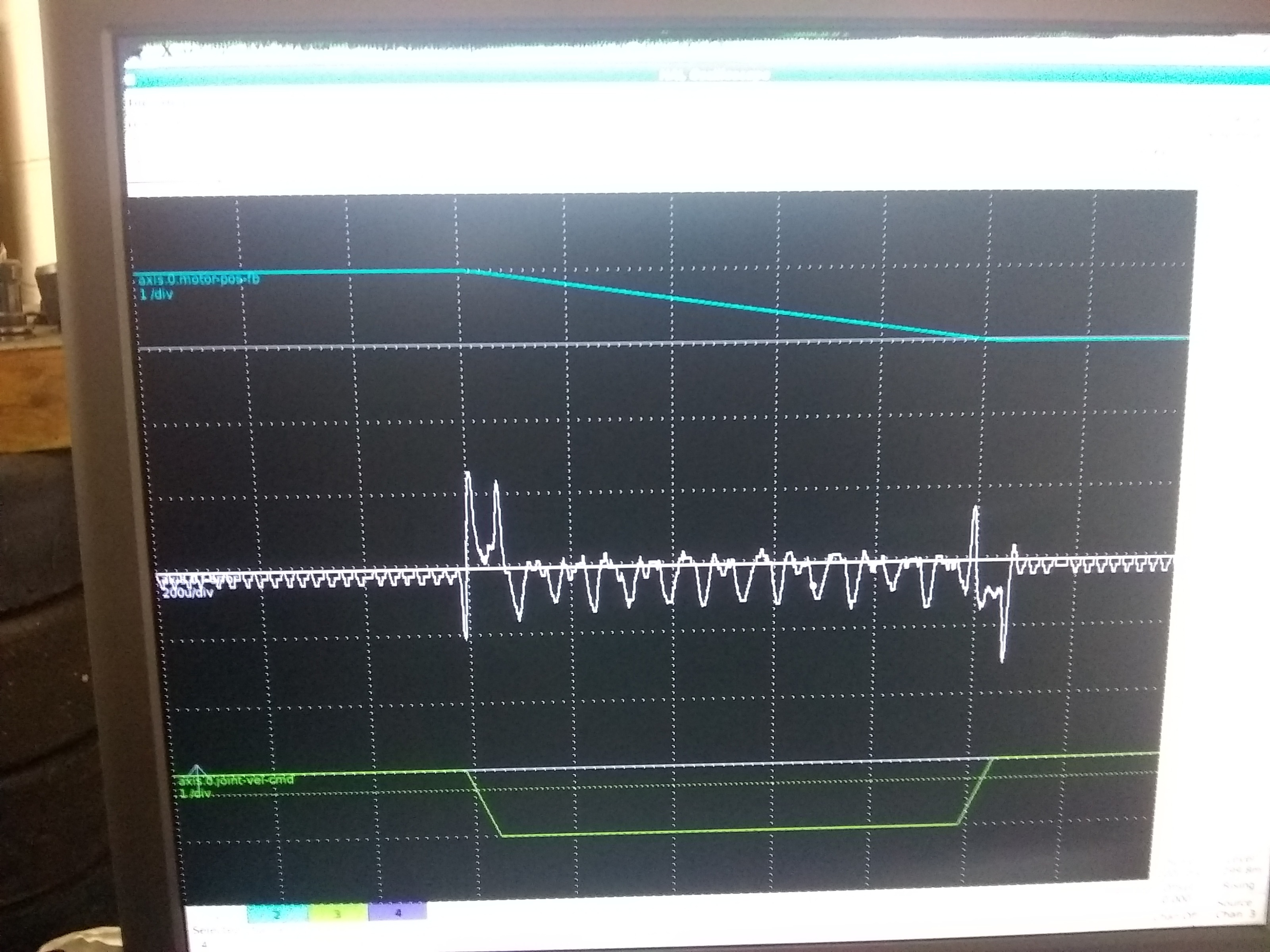
Just posting a quick update and big thank you for patiently answering my stupid questions. I've yet to map the ballscrews but tunning looks good to me anyway. I got it to a little better than .0002" which is good enough for the work I do. I read in one post on here that the best case scenario is 2 encoder pulses.Was wondering what you guys thought? Is it good or should I still keep tweaking?
Please Log in or Create an account to join the conversation.
- Visoq
- Offline
- New Member
-

Less
More
- Posts: 1
- Thank you received: 0
03 Apr 2025 16:46 #325629
by Visoq
Replied by Visoq on topic Hurco Hawk 5M Retrofit w/ existing motors
I have the same machine and was wondering if you would share your info on the motor and drives. I have the 7i97t and trying to figure out where to start.
thanks
thanks
Please Log in or Create an account to join the conversation.
Time to create page: 2.738 seconds