- LinuxCNC
- General LinuxCNC Questions
- Circular path (or any path that require two axis movement at one time)
Circular path (or any path that require two axis movement at one time)
- Python
- Offline
- New Member
-

- Posts: 12
- Thank you received: 0

I'll try to answer all your posts for the better communication and understanding what's actually happening.
********************************************************************************************************************************************************
To Leon82: I tried both already(conventional and climb milling), but there is no change in the cut.Are you climb milling?
If there is slack the tool can be pulling the slack forward.
Try conventional milling a pass
********************************************************************************************************************************************************
To Todd Zuercher: Yes Todd, there is no worn parts, because it's build recently and it wasn't working a lot. But what else can cause not smooth motion? I wonder how to check meshing correctly...? The belts looks fine, they're not tightened to much IMHO.
Yes, Todd, both axis are rack and pinion. I'll check meshing as soon as possible.
PCW, in my opinion and observation there is no wobble in gearing. The belt isn't tightened to much. IMHO.
But I'll check it one more time, to be sure.
Rack and pinions can be tricky to set up right. I have battled with similar problems on some $70k factory built machines. On those machines the problem is usually worn bearings on the pinion shafts, and/or worn bearings on the intermediate shaft of the belt reduction between the servo motor and the pinion. (I am replacing these parts on these 2 machines every 2-3 years)
But any misalignment of the pinion to the rack can lead to not smooth motion. Worn pinion gears can also give these results, but that shouldn't be a problem on a new build.
********************************************************************************************************************************************************
To tommylight: Yes, I've been kind of checking spring movement with my fingers and just looking at it, now that I'm writing this post, I think, that it would be interesting to test it with gauge.Watch the springs while the machine is cutting, they are likely moving while cutting. Getting the right ammount of pressure on those things is very hard as that depends on a lot of mechanical stuff, like how far is the axis that the reduction is mounted on, what angle it is set at etc.
********************************************************************************************************************************************************
I wonder if the distance is related to the pitch of your screw. And if the distance in both axis is equal.
I understand that you have the big whell directly connected to the screw. If distance is smaller as pith, have a look to the small wheel. If bigger than pitch look if it is the factor of big wheel tooth to length/teeth of belt. If it's equal pitch look big wheel. None of them : take a beer or two ;-(
Mike
To Mike_Eitel: About which screw you've been talking about? yess... beer sometimes kind of "helps" for that moment, by the way thanks
")
********************************************************************************************************************************************************
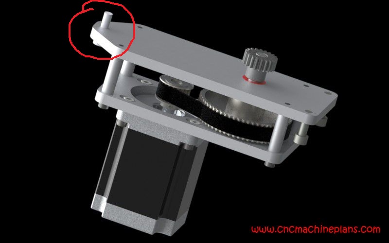
To rodw: Coupling is only mounted to Z axis plate. And it's not helical cut. X and Y axies are designed as shown in the picture below:Also if you have helical cut misalignment shaft joiner, the motor torque can easily exceed the design limits of the joiner and result in backlash within the coupling. I moved to a fairly expensive oldham style coupling to eliminate that

********************************************************************************************************************************************************
To tommylight: I checked a lot of times, also tried replacing pinion's sometimes it's even worse, and I don't know what to do for the moment and what is causing it..... Yes, I changed a lot in INI and HAL files, but nothing, that was generated by STEPCONF.After some analysing it looks like you have something sloppy there as the distance of the anomaly is not exactly the same always.
Check well everything, there is no easier way to say it.
BTW, did you edit anything in the INI and HAL files ?
I added things like debounce for inductive end sensors because of VFD noise, changed home directory of G-Code, etc...
But MACH3 cut the same part exactly the same as LinuxCNC do, so not software problem.
********************************************************************************************************************************************************
Speed variation in a cut on only one axis will not show up in the work, it is only when you have two axes moving that you see the problem.
So, this is because one or more axes are not moving at a steady speed.
This could be mechanical, it could also be in the motor controllers if these are closed-loop steppers or step-servos.
I did at first think that it could be the PID tuning in LinuxCNC (there is a PID even with steppers) but the Mach3 swap eliminated that possibility.
So, what motors and drivers are you using?
I see now that you said it was steppers and simple step/dir drivers.
I think that analysing the pitch of the waves (orthogonal to each axis) is likely to be a very instructive step. Does it match one turn of a shaft, or one turn of a gear.
To andypugh: Yes it's constant. But the situation is that:
After some analysing it looks like you have something sloppy there as the distance of the anomaly is not exactly the same always.
The wiggle pitch will vary depending on the direction of motion. (but, if mechanical) should be constant if projected to an axis.
This picture shows the result of a constant wiggle on X combined with a constant Y at various angles.
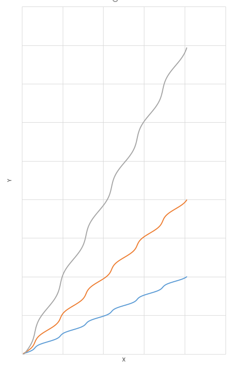
You will see nothing in a straight Y move (as X doesn't move) and nothing in a straight X move (As the wiggle is along the cut line)
1st setup of the machine was, that pinion was directly mounted on Nema34 (rack and pinion module 1.5 straight teeth(pinion 20 teeth))
2nd setup of the machine is that, I designed transfer 4:1 (Nema34:pinion) (rack and pinion module 2.0 straight teeth(been 18 teeth, now it's 22)), but comparing two parts, that are cut now, and was cut then with the first setup, the wiggle looks kind of the same. So I am so lost in this situation, that I don't know what to do.....
Please Log in or Create an account to join the conversation.
- Todd Zuercher
-

- Offline
- Platinum Member
-

- Posts: 4753
- Thank you received: 1458
With that design my first suspect for alignment problems would be the pivot axle here.
It does not look sufficient for maintaining alignment to me.
Attachments:
Please Log in or Create an account to join the conversation.
- andypugh
-

- Offline
- Moderator
-

- Posts: 19871
- Thank you received: 4640
To andypugh: Yes it's constant.
What pitch? Does it match anything in the mechanics?
How have you mounted the gears on the shafts?
Please Log in or Create an account to join the conversation.
- Mike_Eitel
-

- Offline
- Platinum Member
-
- Posts: 1052
- Thank you received: 183
Completely different approach:
Unplug x and y dir and puls signals.
Take an oscillator and a divider (Flip Flop)
First connect x-puls input directly to oscillator and y-puls to divided by two of Flip Flop
Then do it inverse.
By the frequency of your error you should be able to judge which of the two axes ist the guilty. I suspect the one without error will not change the wobble.
Please Log in or Create an account to join the conversation.
- Python
- Offline
- New Member
-
- Posts: 12
- Thank you received: 0
To Andypugh: yes, it seems that it mirrors every teeth in the rack.
1. When jogging seperate axis freely to determine which has the greater vibrations, we found out that X axis is causing all of vibrations, while Y axis moves smooth as butter.
2. So we decided to improve X axis design and we came up with stronger insert (sleeve) that the one before. In a result the milling results got better, not perfect, but acceptable.
3. Also we added a little bit softer spring, that reduces vibrations and eats up some of design flaws. Also it holds pinion tightened up to the rack.
4. We tried to mill some parts in all work table area, but then we saw, that measurments of the parts are incorrect and sometimes it is almost 1mm, so I build up compensation table (done this before with the old design), but now there are new problems. When I press Home button, but only X axis is unhomed, machine is homing and getting speed, but then sudenlly it stops and there is an error joint 0 following error. This problem occured only then I added rack compensation table. Any ideas?
Please Log in or Create an account to join the conversation.
- Python
- Offline
- New Member
-
- Posts: 12
- Thank you received: 0
As we found out it's purely machine iteself not the electronics, and also we don't have the equipment needed to try out the method you mentioned to try it out we skipped this solution.
But thank you very much for the input.
Please Log in or Create an account to join the conversation.
- rodw
-

- Offline
- Platinum Member
-
- Posts: 11983
- Thank you received: 4082
forum.linuxcnc.org/30-cnc-machines/31509...pinion-drive?start=0
Then maybe reconsider your design
Please Log in or Create an account to join the conversation.
- andypugh
-
- Offline
- Moderator
-
- Posts: 19871
- Thank you received: 4640
1. When jogging seperate axis freely to determine which has the greater vibrations, we found out that X axis is causing all of vibrations, while Y axis moves smooth as butter.
Maybe swapping the rack and pinion for a helical pair would help?
sudenlly it stops and there is an error joint 0 following error. This problem occured only then I added rack compensation table. Any ideas?
I think that you have to make sure that your following-error limit is bigger than the backlash numbers.
Please Log in or Create an account to join the conversation.
- Python
- Offline
- New Member
-
- Posts: 12
- Thank you received: 0
andypugh: yes, I've been thinking from the very beginning about helical rack and pinion for all axis except z, but I was that person that was building this machine and the other one is funding and he decided to go cheap, no we are facing consequences.
about error, I tweaked a *.ini file. I put a little bit bigger numbers for min_error and ferror and now it looks like it's working.
Thanks again.
For now, I Think, that we go with this setup and see what's is going to challenge next, if there will be more and more chalanges, I',m thinking about changing design and rack and pinion system to helical one.
Please Log in or Create an account to join the conversation.
- rodw
-
- Offline
- Platinum Member
-
- Posts: 11983
- Thank you received: 4082
I',m thinking about changing design and rack and pinion system to helical one.
I have both straight and helical racks (from Noueli) on my machine. The helical is so much nicer...
Please Log in or Create an account to join the conversation.
- LinuxCNC
- General LinuxCNC Questions
- Circular path (or any path that require two axis movement at one time)