Error message "Radius to end of arc differs....etc etc"
- Jocman
- Offline
- Premium Member
-

Less
More
- Posts: 111
- Thank you received: 11
02 May 2019 18:24 #132552
by Jocman
Error message "Radius to end of arc differs....etc etc" was created by Jocman
Hi all.
It's 2 days I'm getting this annoying message and no possibility to run any job; I'm getting little bit frustrated....
Since untill today I really didn't do any....real job; I just ran some - a lot.... - of test jobs to check various settings before risk; and till now everithing was great: just little test jobs (max 10*15 cm) but enough to me to "be happy".
2 days ago, as my cats destroyed their catflap, I decided to use my cnc to meake a new one; it's a simple rectangle with rounded corner, a small draw and 2 hinge pockets (file attached).
I made 2 gcode files: 1 for the draw (engraved by 0.1mm30° bit), 1 for the catflap (milled by an end mill 2 mm).
The first file (the draw) was great: but when I ran the 2nd, I got the error message (attached - this one is not related to the .ngc file attached, as i made some tries, but getting the same message).
I made and re-made the draw and the path calculations (aspire) and the gcode several times, but nothing changed, same error message.
I searched on the web, and found several topics in various forums concerning this issue, so I tried to fix it someway.
The last try has been to add a G90.1 command at the beginning, but once again no success.
I red about some TOLERANCE_INCH and TOLERANCE_MM to put in the .ini file, red about the use of a wrong bit (to big for the radious - but my rectangle has rounded corners with 25 mm of radius and the bit is 2mm....) and so on....
But I can't fix the problem....And the machine doesn't wont to work....
For the sake of honesty, I request help even to the italian forum, but no answer....
So, what's wrong with these radius??? and moreover, how is it possible that an arc (a regular arc) has different start and end radius (it's a cyrcle arc, not a hyperbola or ellipse)......
Thanks in advance
Andrea
Please Log in or Create an account to join the conversation.
- Todd Zuercher
-

- Away
- Platinum Member
-

Less
More
- Posts: 4764
- Thank you received: 1464
02 May 2019 19:05 - 02 May 2019 19:06 #132557
by Todd Zuercher
Replied by Todd Zuercher on topic Error message "Radius to end of arc differs....etc etc"
You either need to decrease the arc tolerance in you cam program (so it outputs more precice code) or increase the "center arc radius tolerance" setting in Linuxcnc.
linuxcnc.org/docs/html/config/ini-config.html#_rs274ngc_section
Changing the inch setting from 0.00005 to 0.0001 should be close enough for Linuxcnc to open and run your example file.
linuxcnc.org/docs/html/config/ini-config.html#_rs274ngc_section
Changing the inch setting from 0.00005 to 0.0001 should be close enough for Linuxcnc to open and run your example file.
Last edit: 02 May 2019 19:06 by Todd Zuercher.
Please Log in or Create an account to join the conversation.
- Jocman
- Offline
- Premium Member
-
Less
More
- Posts: 111
- Thank you received: 11
03 May 2019 07:14 #132608
by Jocman
Replied by Jocman on topic Error message "Radius to end of arc differs....etc etc"
Thankyou.
I'll give it a try
I'll give it a try
Please Log in or Create an account to join the conversation.
- Jocman
- Offline
- Premium Member
-
Less
More
- Posts: 111
- Thank you received: 11
04 May 2019 09:54 - 04 May 2019 09:55 #132714
by Jocman
Replied by Jocman on topic Error message "Radius to end of arc differs....etc etc"
Yesterday I tried someways:
1) by putting the 2 lines:
CENTER_ARC_RADIUS_TOLERANCE_INCH = n
CENTER_ARC_RADIUS_TOLERANCE_MM = n
in the ini file, RS274NGC section
2) by setting the tolerance in Aspire
Both ways, no success at all. More, it seems linuxcnc to ignore completely the 2 added lines, as even by changing the tolerance values, the messages keep reporting the same percentage of tolerance error.
At the end I tried with tolerance 0 in Aspire (maybe wrong?) and high tolerance value in .ini file (1" and 1 mm - wrong this too?)
I keept having the same error.messages.....
Eventually, I decided to draw the rounded rectangle in a vectorial software (inkscape), export as DWG and import it to aspire.
Everything was fine.
Just I noticed that the arcs are now processed as linear movements (G1) instead of arcs (G3).
Actually I'm using Aspire just to generate the Gcode, normally I draw in inkscape.
I know this definitively is not a solution, but I don't know what else to do....
Last edit: 04 May 2019 09:55 by Jocman.
Please Log in or Create an account to join the conversation.
- tommylight
-

- Away
- Moderator
-

Less
More
- Posts: 21764
- Thank you received: 7438
05 May 2019 02:31 #132801
by tommylight
Replied by tommylight on topic Error message "Radius to end of arc differs....etc etc"
You can draw in Inkscape and output it directly as a gcode for use with Linuxcnc.
Check gcodetools, they are already included with Inkscape.
Check gcodetools, they are already included with Inkscape.
Please Log in or Create an account to join the conversation.
- Jocman
- Offline
- Premium Member
-
Less
More
- Posts: 111
- Thank you received: 11
06 May 2019 07:11 #132926
by Jocman
Replied by Jocman on topic Error message "Radius to end of arc differs....etc etc"
Thanks for the suggestion, I think I'll do it.
Andrea
Andrea
Please Log in or Create an account to join the conversation.
- pl7i92
-

- Offline
- Platinum Member
-
Less
More
- Posts: 1872
- Thank you received: 358
06 May 2019 09:07 #132939
by pl7i92
Replied by pl7i92 on topic Error message "Radius to end of arc differs....etc etc"
can you upload a high reolution image of the Drawing we make you a near perfect G-code
Please Log in or Create an account to join the conversation.
- Todd Zuercher
-
- Away
- Platinum Member
-
Less
More
- Posts: 4764
- Thank you received: 1464
06 May 2019 13:20 #132957
by Todd Zuercher
Replied by Todd Zuercher on topic Error message "Radius to end of arc differs....etc etc"
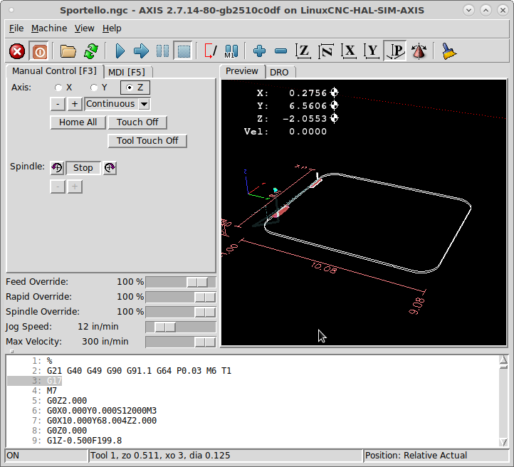
I took a closer look at your G-code and I now see your problem. The problem is that the arc centers are specified in incremental mode not absolute coordinates. Your code will run fine if you change the beginning line of your file fromtoThen it should run fine.
G21 G40 G49 G90.1 G64 P0.03 M6 T1G21 G40 G49 G90 G91.1 G64 P0.03 M6 T1Please Log in or Create an account to join the conversation.
- Jocman
- Offline
- Premium Member
-
Less
More
- Posts: 111
- Thank you received: 11
06 May 2019 13:23 - 06 May 2019 13:23 #132958
by Jocman
Replied by Jocman on topic Error message "Radius to end of arc differs....etc etc"
Here you find a DWG of the catflap (with no graphics.)
Yesterday I made it by using my "no solution" code, and honestly the result is fine (my soulmate loves it and that makes my life easier )
)
BTW I'd like to fix the problem of the G3 command in vectric/LinuxCNC, as I'm really thinking to get Aspire (or even the cheaper 2DCut), but if I can't fix the arc problem it will be almost useless to buy it, better keep using Inkscape with Gcode support (and the "no solution" method.....)
Andrea
Yesterday I made it by using my "no solution" code, and honestly the result is fine (my soulmate loves it and that makes my life easier
)BTW I'd like to fix the problem of the G3 command in vectric/LinuxCNC, as I'm really thinking to get Aspire (or even the cheaper 2DCut), but if I can't fix the arc problem it will be almost useless to buy it, better keep using Inkscape with Gcode support (and the "no solution" method.....)
Andrea
Last edit: 06 May 2019 13:23 by Jocman.
Please Log in or Create an account to join the conversation.
- Todd Zuercher
-
- Away
- Platinum Member
-
Less
More
- Posts: 4764
- Thank you received: 1464
06 May 2019 14:48 #132967
by Todd Zuercher
Replied by Todd Zuercher on topic Error message "Radius to end of arc differs....etc etc"
Your old G-code works fine if you change the first line.
Attachments:
Please Log in or Create an account to join the conversation.
Time to create page: 0.269 seconds