Mitsubishi RV-6SDL Robot arm Servo/Encoder usability
- dm17ry
-

- Offline
- Elite Member
-

Less
More
- Posts: 193
- Thank you received: 78
08 Jan 2020 09:15 #154294
by dm17ry
Replied by dm17ry on topic Mitsubishi RV-6SDL Robot arm Servo/Encoder usability
your encoders will work fine with 2-wire connection
The following user(s) said Thank You: Aciera
Please Log in or Create an account to join the conversation.
- Aciera
-
 Topic Author
- Offline
- Administrator
-

Less
More
- Posts: 4648
- Thank you received: 2068
16 Dec 2020 07:03 - 16 Dec 2020 07:04 #192105
by Aciera
Replied by Aciera on topic Mitsubishi RV-6SDL Robot arm Servo/Encoder usability
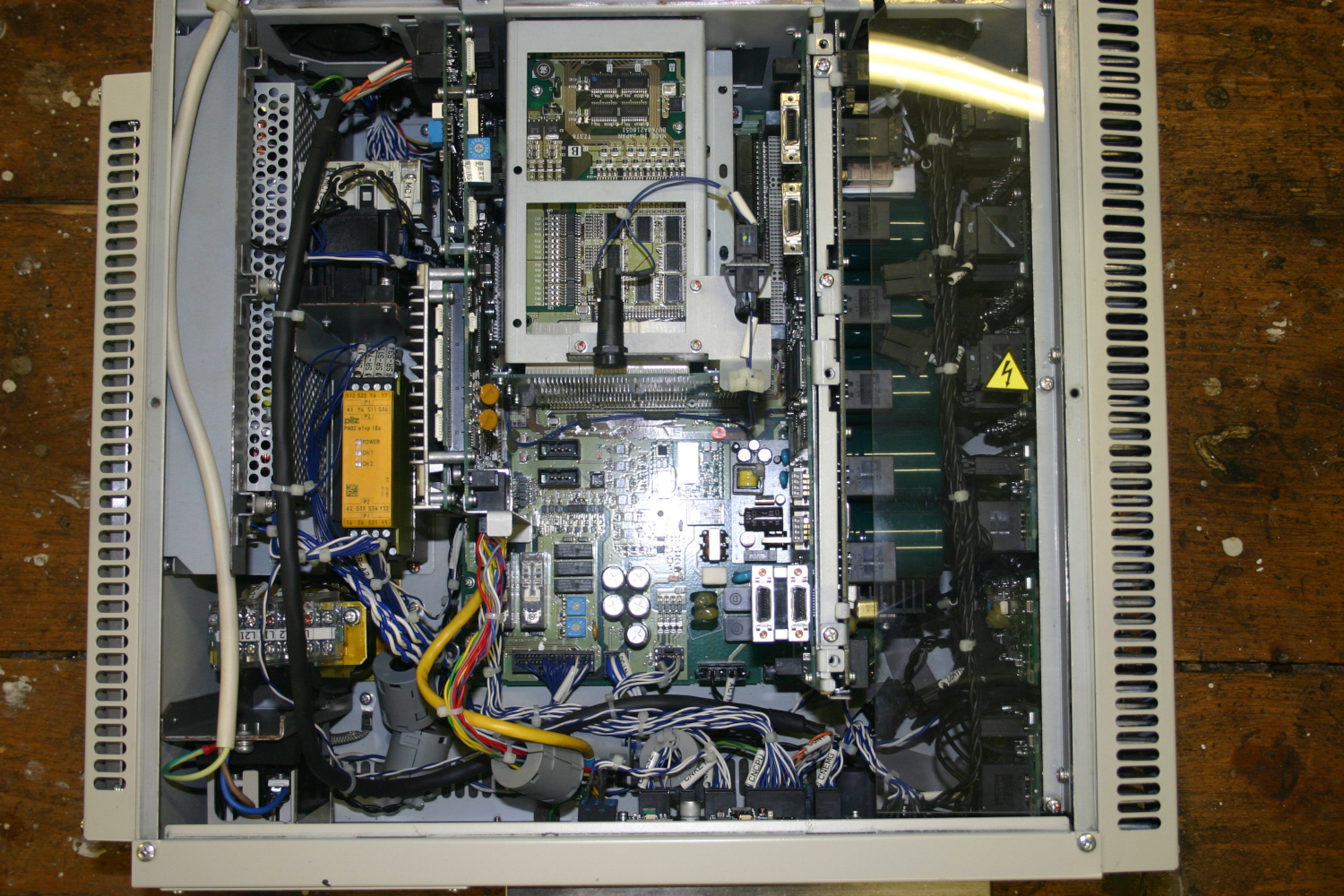
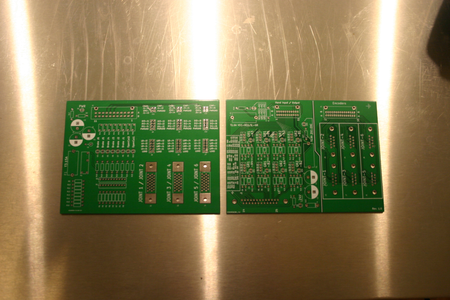
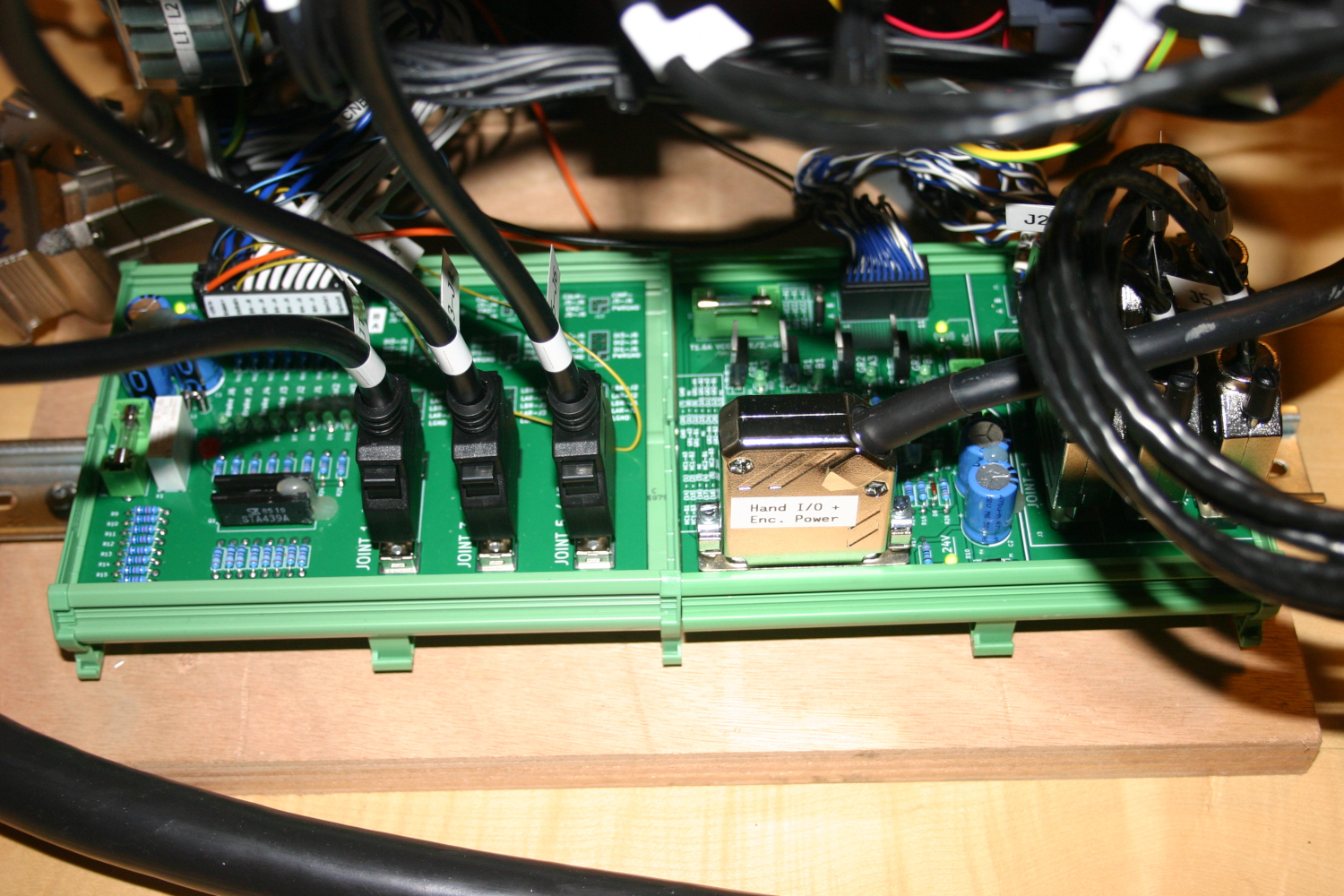
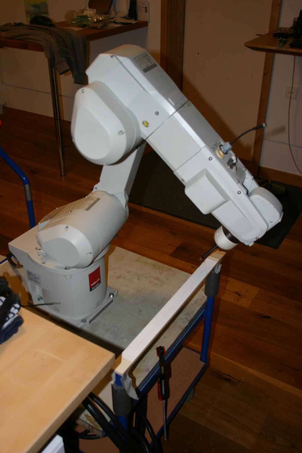
So after weighing my options I finally moved forward with this robot and it's broken controller. Since dm17ry is an expert on mitsubishi drives and motors and has some pretty awesome insights in the technology used I was able to get the servos running with some used mitsubishi J4 drives.
The original controller:
Had some PCBs made up to interface the drives with the original connectors:
And in action:
The original controller:
Had some PCBs made up to interface the drives with the original connectors:
And in action:
Attachments:
Last edit: 16 Dec 2020 07:04 by Aciera.
Please Log in or Create an account to join the conversation.
- Aciera
-
 Topic Author
- Offline
- Administrator
-

Less
More
- Posts: 4648
- Thank you received: 2068
16 Dec 2020 07:24 - 16 Dec 2020 08:26 #192106
by Aciera
Replied by Aciera on topic Mitsubishi RV-6SDL Robot arm Servo/Encoder usability
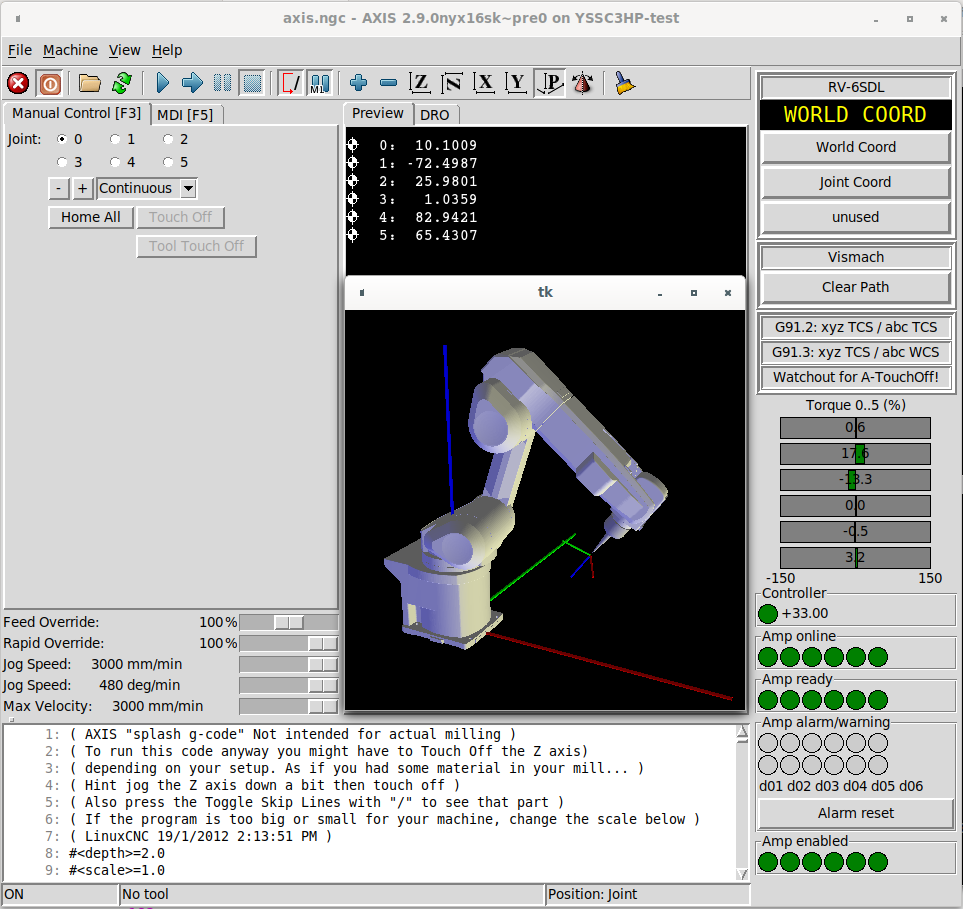
The whole affair now looks like this:
After dm17ry kindly merged his branch with the switchkins branch I was able to bring in my config with the vismach simulation and the genserkins setup for my robot arm (forum.linuxcnc.org/10-advanced-configura...nfig-with-simulation).
The driver passes the joints position from the absolute encoders (17bit, 131072 pulses per motor revolution) through to LinuxCNC and automatically sets the axis as homed if the encoder position is valid. This solves the issue of having to rehome the arm every time the system is started, which would have been a major headache.
Attachments:
Last edit: 16 Dec 2020 08:26 by Aciera. Reason: change pic
The following user(s) said Thank You: chimeno, tommylight, Clive S, dm17ry
Please Log in or Create an account to join the conversation.
- Aciera
-
 Topic Author
- Offline
- Administrator
-

Less
More
- Posts: 4648
- Thank you received: 2068
21 Dec 2020 07:48 - 21 Dec 2020 07:49 #192611
by Aciera
Replied by Aciera on topic Mitsubishi RV-6SDL Robot arm Servo/Encoder usability
Made a first video with a tentative test:
user-images.githubusercontent.com/460672...7d4-24273a026c54.mp4
user-images.githubusercontent.com/460672...7d4-24273a026c54.mp4
Attachments:
Last edit: 21 Dec 2020 07:49 by Aciera.
The following user(s) said Thank You: chimeno, tommylight
Please Log in or Create an account to join the conversation.
- Clive S
- Offline
- Platinum Member
-

Less
More
- Posts: 2203
- Thank you received: 482
22 Dec 2020 10:47 #192801
by Clive S
Replied by Clive S on topic Mitsubishi RV-6SDL Robot arm Servo/Encoder usability
Are you aware of this and is it useful
The following user(s) said Thank You: Aciera
Please Log in or Create an account to join the conversation.
- Aciera
-
 Topic Author
- Offline
- Administrator
-

Less
More
- Posts: 4648
- Thank you received: 2068
22 Dec 2020 14:25 - 22 Dec 2020 14:51 #192817
by Aciera
Replied by Aciera on topic Mitsubishi RV-6SDL Robot
@Clive
Thanks for the video.
I was aware that Machinekit is capable to interface with ROS and I have worked a bit with the ROS framework as well but I haven't seen the tormach GUI and the conversational programming they use. The programming is a lot more like the commercial controls with the waypoints as a list and the move commands being pointed to the waypoint numbers. From what I have seen it's not vastly more capable than what I have here using traditional Linuxcnc and mostly I'd like to know if it can do moves in Tool coordinates. Maybe they can but it only shows Joint and World moves.
What is of course much more capable is the visualization in ROS and also collision control in simulation as it actually uses STL's to check for interferences. So you can simulate it running with a model of the actual gripper and a model of the surroundings ie. machine housings and the parts and so on. Being able to drag the robot in the screen looks cool but I don't find that to be terribly useful I think that would be done by jogging the actual robot in the real environment.
Also it would not be using the kinematics like "genserkins" that's built into linuxcnc but use the ROS kinematic library.
Mine works well with linear moves in Tool coordinates but rotations don't work.
Last edit: 22 Dec 2020 14:51 by Aciera.
Please Log in or Create an account to join the conversation.
- Aciera
-
 Topic Author
- Offline
- Administrator
-

Less
More
- Posts: 4648
- Thank you received: 2068
22 Dec 2020 15:40 - 22 Dec 2020 16:00 #192821
by Aciera
Replied by Aciera on topic Mitsubishi RV-6SDL Robot
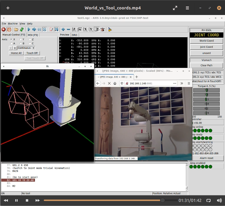
Made a new video to show World - vs Tool-coordinates:
user-images.githubusercontent.com/460672...e1a-eaa703d26b18.mp4
[edit]
This is the GCODE that is running in the video:
[edit2]
And here is the python remap for the "G91.2" command used in the program. I'm a clumsy programmer so it's probably a mess to somebody who actually know what he's doing and also likely why the rotations don't work properly
[edit3]
Note: I don't claim to have come up with the python script all by myself. I usually shamelessly copy/paste and modify what I can find on the net. So if anybody recognizes parts of it please leave a comment. IIRC I heavily leaned on work by Rudy du Preez.
user-images.githubusercontent.com/460672...e1a-eaa703d26b18.mp4
[edit]
This is the GCODE that is running in the video:
Warning: Spoiler!
(Wait for me to start the screen capture)
(G04 P5)
(Preamble)
G90 G64 P0.1 Q1
(Switch to Joint mode trivial kinematics)
M429
(When using "Joint" mode we need to make sure that)
(the offsets are set correctly for the pose we used)
(when we set up the Modified DH-Parameters for the )
("genserkins" kinematic where we cannot define 'Theta')
(-values.)
("M429" sets offsets to "G59.2" and resets those)
(to "G10 L2 P8 X0 Y-90 Z0 A0 B0 C0" so we match the DH-)
(Parameter model used in the genserkins kinematics)
(Note that this pose leaves Joint_3 and Joint_5 collinear)
(and that will cause the inverse kinematics to fail so we)
(need to make sure that the wrist does not start out at)
(zero degrees.)
(Note that we also change speed settings through HAL when)
(we switch kinematics)
(Set the start pose to make sure the kinematics can handle it)
G01 X0 Y0 Z0 A0 B0 C0 F1000
(Switch to Coordinated, i.e. cartesian, world mode)
M428
("M429" sets offsets to "G59.2" and resets those)
(to "G10 L2 P7 X0 Y0 Z0 A0 B0 C0")
(Origin is at bottom center of the robot base)
(So to use other, nonzero, offsets we need to declare after)
(each switch of the kinematics)
G0 X450 Y200 Z350 B10 C45
(Draw a cube of 150mm)
G91
G01 Y150 F4000
X150
Y-150
X-150
Z150
Y150
Z-150
Z150
X150
Z-150
Z150
Y-150
Z-150
Z150
X-150
Y-200
(Now draw the same cube in the current tool coordinates)
(using the custom "G91.2" python remap)
G90
G91.2 Y150 F1000
G91.2 X150
G91.2 Y-150
G91.2 X-150
G91.2 Z150
G91.2 Y150
G91.2 Z-150
G91.2 Z150
G91.2 X150
G91.2 Z-150
G91.2 Z150
G91.2 Y-150
G91.2 Z-150
G91.2 Z150
G91.2 X-150
(Switch to Joint mode trivial kinematics)
M429
(Go to start pose)
G01 X0 Y0 Z0 A0
M2
[edit2]
And here is the python remap for the "G91.2" command used in the program. I'm a clumsy programmer so it's probably a mess to somebody who actually know what he's doing and also likely why the rotations don't work properly
[edit3]
Note: I don't claim to have come up with the python script all by myself. I usually shamelessly copy/paste and modify what I can find on the net. So if anybody recognizes parts of it please leave a comment. IIRC I heavily leaned on work by Rudy du Preez.
Attachments:
Last edit: 22 Dec 2020 16:00 by Aciera.
The following user(s) said Thank You: chimeno, tommylight
Please Log in or Create an account to join the conversation.
- Aciera
-
 Topic Author
- Offline
- Administrator
-

Less
More
- Posts: 4648
- Thank you received: 2068
26 Dec 2020 10:49 - 26 Dec 2020 10:49 #193216
by Aciera
Replied by Aciera on topic Mitsubishi RV-6SDL Robot
A little update:
I found a solution for mounting the DELL Optiplex and Dmitrys PCI board connected to the miniPCIe through an adapter. I had some trouble getting the PCI adapter recognized but it was all resolved after a BIOS reset.
The idea is to be able to fit everything into a 600x400x300mm metal enclosure.
I had a bit of a setback as I crashed the 4th joint into it's limits while trying out a new version of my python script. It still works but it clearly has taken a hit as it now needs a lot more torque to jog and it sounds a bit rough when moving it at higher velocities. So this led me to reconsider my approach and while the arm didn't cost me that much I don't want to wreck it by doing something that could be prevented.
While the soft limits were working fairly reliably before the motion planner clearly missed to prevent the crash that came after the A angle value switched from positive to negative value which led to the forearm twist at maximum speed.
I decided that before running code on the real arm I need to run it in a simulation.
Attachments:
Last edit: 26 Dec 2020 10:49 by Aciera.
The following user(s) said Thank You: tommylight
Please Log in or Create an account to join the conversation.
- dm17ry
-

- Offline
- Elite Member
-

Less
More
- Posts: 193
- Thank you received: 78
27 Dec 2020 08:31 #193276
by dm17ry
Replied by dm17ry on topic Mitsubishi RV-6SDL Robot
ouch! but why didn't the joint limit prevented the crash? too close to the mechanical stop and didn't have time to decelerate or..?
Please Log in or Create an account to join the conversation.
- Aciera
-
 Topic Author
- Offline
- Administrator
-

Less
More
- Posts: 4648
- Thank you received: 2068
27 Dec 2020 09:52 #193278
by Aciera
Replied by Aciera on topic Mitsubishi RV-6SDL Robot
Not really sure as to why the joint limit didn't prevent it. But the motion was fairly instantaneous so I think there was just no time. The motion planner certainly didn't prevent the execution of the command.
One thing that I find quite tricky is to set the maximum accellerations and velocities correctly for cartesian world mode. Sometimes linear moves are quite slow but when only angular moves ABC are involved everything happens _really_ fast. May also have something to do with the fact that for LCNC XYZ are linear and ABC are angular no matter what you declare in the INI.
In any case I clearly had my settings too high.
I'm trying to merge the nyx-s_kins-branch with the dryrun-branch to be able to simulate before running code but I haven't succeeded yet.
github.com/LinuxCNC/linuxcnc/tree/dgarr/dryrun
Please Log in or Create an account to join the conversation.
Time to create page: 0.345 seconds

