Is it possible to display the cutting path in 3D in QTPlasmac?
- DmitryKV
- Offline
- Junior Member
-

Less
More
- Posts: 21
- Thank you received: 1
25 Sep 2023 09:22 #281586
by DmitryKV
Is it possible to display the cutting path in 3D in QTPlasmac? was created by DmitryKV
Hello.
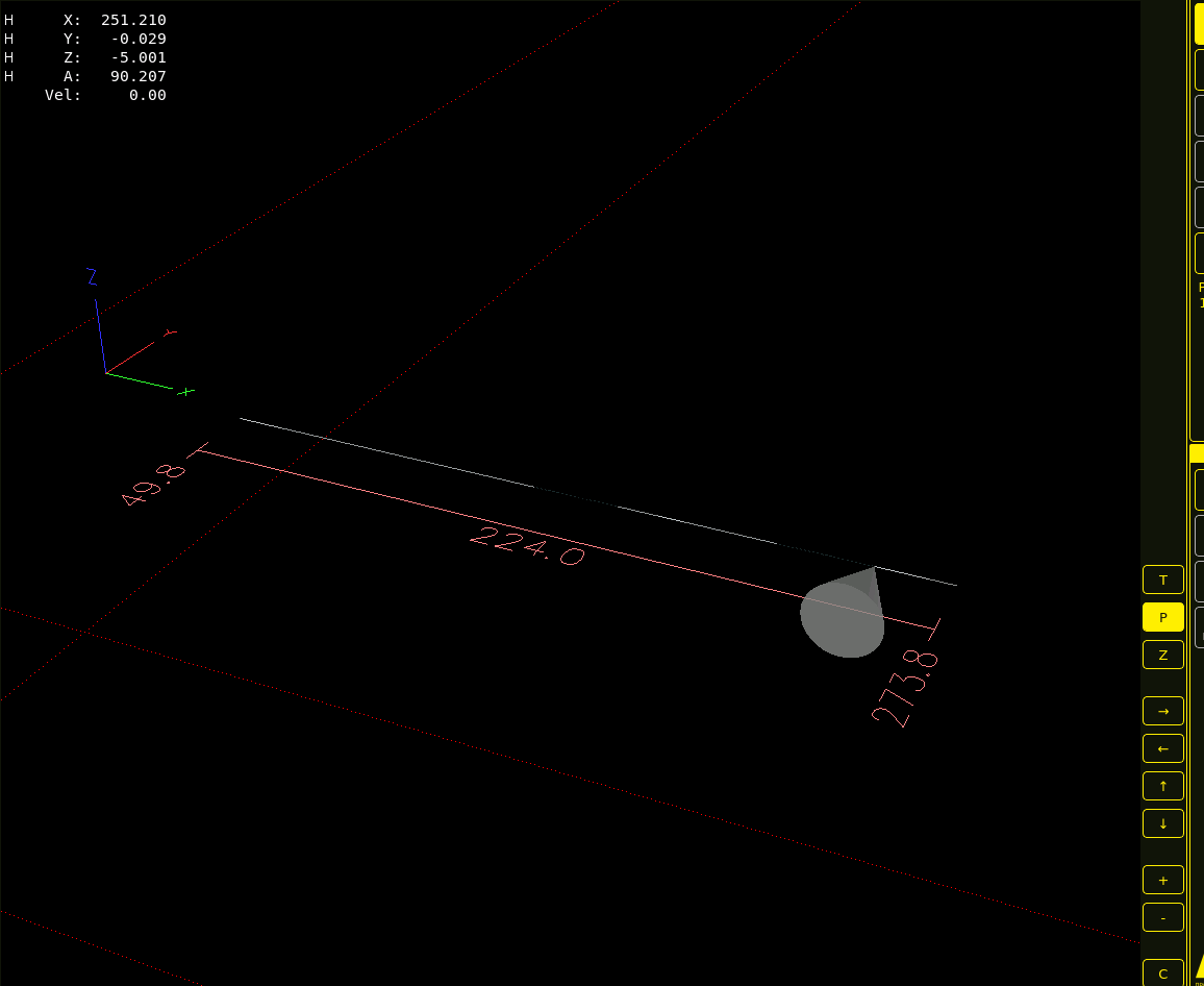
I have a portal machine. I added a pipe cutting module to it. The tube cutting module is configured as A-axis. Physically, the pipe cutting attachment works. There are no questions about the cutting process yet. Unfortunately, in the graphic display window everything merges into a line and looks something like this.
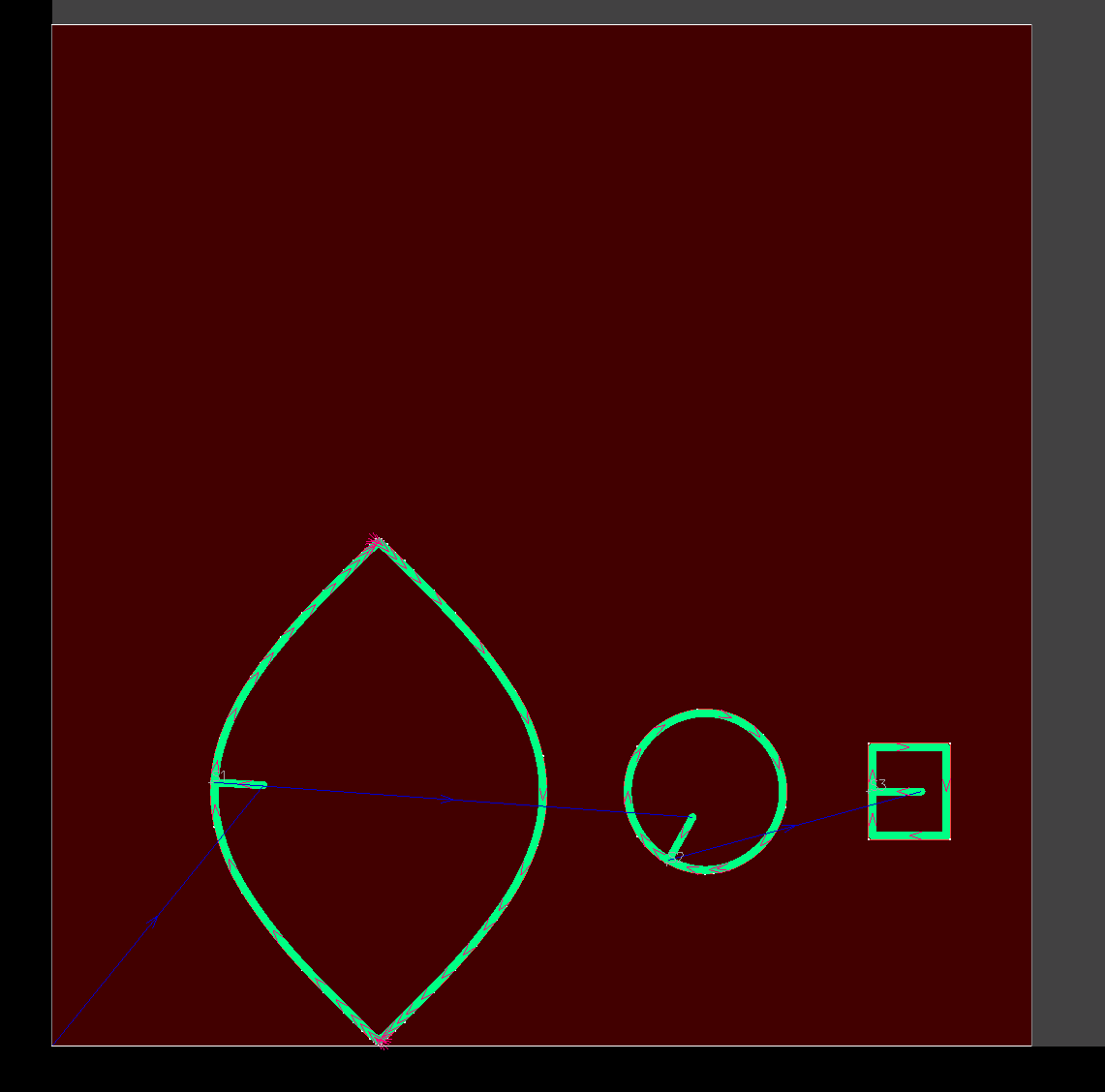
The job in SheetCAM looks like this.
Are there ways to adjust the display in the graphics window so that the A axis does not rotate around a point, but moves in the volume?
I will be glad to any hints. All my attempts were unsuccessful.
Regards, Dmitry.
Attachments:
Please Log in or Create an account to join the conversation.
- cmorley
- Offline
- Moderator
-

Less
More
- Posts: 7289
- Thank you received: 2127
25 Sep 2023 22:17 #281617
by cmorley
Replied by cmorley on topic Is it possible to display the cutting path in 3D in QTPlasmac?
What is the diameter of the pipe you are cutting?
Looks like A revolves around X.
Does Y set the diameter?
Looks like A revolves around X.
Does Y set the diameter?
Please Log in or Create an account to join the conversation.
- DmitryKV
- Offline
- Junior Member
-

Less
More
- Posts: 21
- Thank you received: 1
26 Sep 2023 01:37 #281625
by DmitryKV
Replied by DmitryKV on topic Is it possible to display the cutting path in 3D in QTPlasmac?
Hello.
Yes You are right. The A axis rotates around the X axis. The Y axis is not used when cutting a round pipe; it is used only on a square one. Axis A is configured as ANGULAR. In fact, the pipe diameter is not specified in Linux. To prepare G code I use the Rotary Plasma plugin of SheetCAM. The pipe diameter is specified only there. The cutting is transmitted 2D to SheetCAM.
In principle, I am ready to try changing the configuration of the machine if this solves the visualization issue.
Regards, Dmitry.
Please Log in or Create an account to join the conversation.
- cmorley
- Offline
- Moderator
-

Less
More
- Posts: 7289
- Thank you received: 2127
26 Sep 2023 03:19 #281627
by cmorley
Replied by cmorley on topic Is it possible to display the cutting path in 3D in QTPlasmac?
You are cutting the OD of the pipe?
What diameter are you cutting?
Now I may fundamentally not understand what you are doing but...
I think the diameter becomes important for the visualization.
looks like Y is .029 (mm?) so .058 diameter - that is going to be hard to see any detail.
Hopefully Phill will chime in soon - he probably will pick up the solution quicker then me.
Please Log in or Create an account to join the conversation.
- phillc54
-

- Offline
- Platinum Member
-

Less
More
- Posts: 5711
- Thank you received: 2093
26 Sep 2023 05:25 - 26 Sep 2023 05:25 #281631
by phillc54
Replied by phillc54 on topic Is it possible to display the cutting path in 3D in QTPlasmac?
I noticed the same behaviour when I was doing some rotary plasma testing. From memory it was also behaving the same in AXIS. I "think" that I tried A in different positions in [DISPLAY]GEOMETRY but that had no effect. I really have no idea.Hopefully Phill will chime in soon - he probably will pick up the solution quicker then me.
Last edit: 26 Sep 2023 05:25 by phillc54.
Please Log in or Create an account to join the conversation.
- cmorley
- Offline
- Moderator
-

Less
More
- Posts: 7289
- Thank you received: 2127
26 Sep 2023 05:31 #281632
by cmorley
Replied by cmorley on topic Is it possible to display the cutting path in 3D in QTPlasmac?
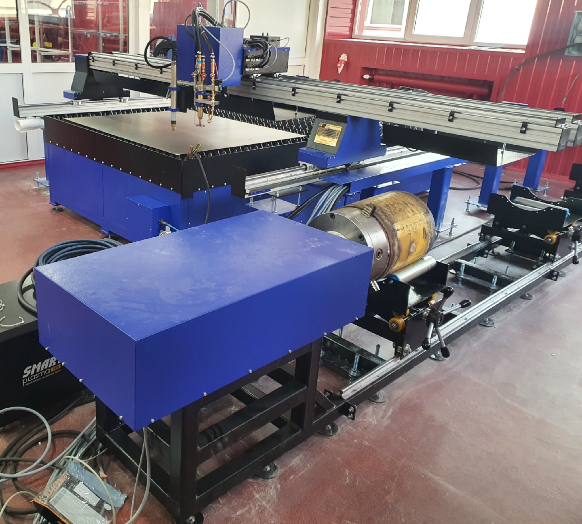
Can you take a picture of your actual machine to help with my visualization?
Please Log in or Create an account to join the conversation.
- DmitryKV
- Offline
- Junior Member
-

Less
More
- Posts: 21
- Thank you received: 1
26 Sep 2023 05:37 #281633
by DmitryKV
Replied by DmitryKV on topic Is it possible to display the cutting path in 3D in QTPlasmac?
I cut pipe in the range from 50 to 300mm. It seems to me that the image should stretch along the Z axis, since the cutter moves along this axis. There is no movement along the Y axis for a round pipe. Only the square one has it.
I also tried different geometries in the [DISPLAY]GEOMETRY settings. It didn't give me any results.
It would be a pity, of course, if nothing comes of the visualization yet.
Regards, Dmitry.
I also tried different geometries in the [DISPLAY]GEOMETRY settings. It didn't give me any results.
It would be a pity, of course, if nothing comes of the visualization yet.
Regards, Dmitry.
Please Log in or Create an account to join the conversation.
- phillc54
-

- Offline
- Platinum Member
-

Less
More
- Posts: 5711
- Thank you received: 2093
26 Sep 2023 06:07 #281635
by phillc54
Replied by phillc54 on topic Is it possible to display the cutting path in 3D in QTPlasmac?
I "think" it is probably caused by all the Z motion being done by external offsets rather than G-code moves.
Please Log in or Create an account to join the conversation.
- cmorley
- Offline
- Moderator
-

Less
More
- Posts: 7289
- Thank you received: 2127
26 Sep 2023 06:09 - 26 Sep 2023 06:10 #281636
by cmorley
Replied by cmorley on topic Is it possible to display the cutting path in 3D in QTPlasmac?
[DISPLAY]GEOMETRY just sets what axis the rotation is applied to.
Looks to me the rotation is applied properly (around x).
I think the visualization is actually correct. Drawing around a diameter of zero (or close to zero) will only show X movement.
ie. draw a face on a piece of 1mm tube will be hard to see - 50mm much easier.
What do you do to touch of to the diameter of the pipe?
if you jog Y to something like 20mm then jog A around 360 degrees, do you see a circle?
Last edit: 26 Sep 2023 06:10 by cmorley. Reason: wrong axis quoted
Please Log in or Create an account to join the conversation.
- DmitryKV
- Offline
- Junior Member
-

Less
More
- Posts: 21
- Thank you received: 1
26 Sep 2023 06:12 #281637
by DmitryKV
Replied by DmitryKV on topic Is it possible to display the cutting path in 3D in QTPlasmac?
Attachments:
Please Log in or Create an account to join the conversation.
Moderators: snowgoer540
Time to create page: 0.146 seconds


