Need help connecting vfdmod and Qtdragon_HD
- oficinerobotica
-
 Topic Author
- Offline
- Senior Member
-

Less
More
- Posts: 47
- Thank you received: 12
03 May 2022 16:11 #241930
by oficinerobotica
Replied by oficinerobotica on topic Need help connecting vfdmod and Qtdragon_HD
@MarcoPolo Where is the handler.py file located?
I got the speed displayed correctly correctly using this in my vfd.hal file.
So my vfd.hal file looks like this atm.
I got the speed displayed correctly correctly using this in my vfd.hal file.
# yl_vfd speed feedback is given in RPM, while some pins need it in
# RPS, so we use a scale
loadrt scale names=scale_to_rpm
---------------------
---------------------
---------------------
addf scale_to_rpm servo-thread
setp scale_to_rpm.gain 0.01666666
net spindle-speed-fb => scale_to_rpm.in
net spindle-speed-in spindle.0.speed-in <= scale_to_rpm.out
So my vfd.hal file looks like this atm.
# yl_vfd speed feedback is given in RPM, while some pins need it in
# RPS, so we use a scale
loadrt scale names=scale_to_rpm

net spindle-speed spindle.0.speed-out => vfdmod.spindle.rpm-in
net spindle-cw spindle.0.forward => vfdmod.control.run-forward
net spindle-ccw spindle.0.reverse => vfdmod.control.run-reverse
net spindle-speed-fb  <= vfdmod.spindle.rpm-out
net spindle-current <= vfdmod.parameters.OutputCurent
net spindle-frequency <= vfdmod.parameters.TargetFrequency
net spindle-voltage <= vfdmod.parameters.OutputVoltage
net spindle-comm-ok <= vfdmod.rs485.is-connected

net spindle-at-speed vfdmod.spindle.at-speed => spindle.0.at-speed

net spindle-current => qtdragon.spindle-amps
net spindle-voltage => qtdragon.spindle-volts

addf scale_to_rpm servo-thread
setp scale_to_rpm.gain 0.01666666
net spindle-speed-fb => scale_to_rpm.in
net spindle-speed-in spindle.0.speed-in <= scale_to_rpm.out
Please Log in or Create an account to join the conversation.
- MarkoPolo
- Offline
- Elite Member
-

Less
More
- Posts: 304
- Thank you received: 83
03 May 2022 21:17 #241944
by MarkoPolo
Replied by MarkoPolo on topic Need help connecting vfdmod and Qtdragon_HD
Your vfd.hal works very well, it worked without any modification, thanks a lot.
The handler.py file is located at /usr/share/qtvcp/screens/gtdragon_hd/
There is also a problem that the motor starts to spin from 50Hz to 400Hz, and the qtdragon at this frequency already shows 3000 rpm.
I don't know how to fix it yet.
The handler.py file is located at /usr/share/qtvcp/screens/gtdragon_hd/
There is also a problem that the motor starts to spin from 50Hz to 400Hz, and the qtdragon at this frequency already shows 3000 rpm.
I don't know how to fix it yet.
Please Log in or Create an account to join the conversation.
- oficinerobotica
-
Topic Author
- Offline
- Senior Member
-
Less
More
- Posts: 47
- Thank you received: 12
04 May 2022 04:58 - 04 May 2022 05:27 #241968
by oficinerobotica
Replied by oficinerobotica on topic Need help connecting vfdmod and Qtdragon_HD
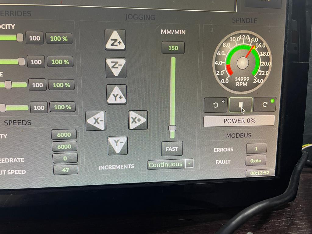
Atm everything works except the power bar and error/fault display underneath the spindle gauge.I still get a s32/u32 error even if I edit the handler.py located at /usr/share/qtvcp/screens/gtdragon_hd/ when trying to display error/faults.
Also I think some pins need to be connected differently in the vfd.hal to have the power bar displayed.
When everything works correctly I would like to edit the first post of this thread with the correct solution.
This is what I have done till now to get the YL620 VFD to work with qtdragon_hd . Bellow the links as a reference because this is not my work. I’m just trying to gather it all together in one place so life should be easier for someone else with the same setup.
forum.linuxcnc.org/qtvcp/42161-qtdragon-pins-rpm-and-docs
github.com/aekhv/vfdmod/wiki
github.com/xsnoopy/LinuxCNC-Yalang-yl620...s485-Modbus---VFDmod
linuxcnc.org/docs/devel/html/gui/qtdragon.html#_spindle
Using LinuxCNC 2.9 on Debian Buster.
This solution is based arround VFDMod and Modbus RS485 communication with a Yalang YL620 Variable Frequency Drive. I am using a RS485 usb adapter as the one in the picture bellow

#1 Set up the Yalang YL620 VFD to drive to receive signals via Modbus.
P00.01 = 3 Start/Stop command source RS485
P03.00 = 4 for 19200Bps
P03.01 = 1 RS485 slave address 1
P03.02 = 2 Data transfer format 8 bit data, 1 stop bit, no parity
P07.08 = 5 Frequency source selection RS 485
#2 Install VFDMod from here github.com/aekhv/vfdmod/releases
#3 Create the vfd.hal and vfd.ini files in your linuxcnc/config/”your_machine_name” folder
vfd.hal
vfd.ini
#4 Make qtdragon_hd correctly display the spindle gauge division
In the .ini file of your machine under [DISPLAY] add
#5 Addto the custom.hal file.
#6 Addto the postgui_call_list.hal file.
Also I think some pins need to be connected differently in the vfd.hal to have the power bar displayed.
When everything works correctly I would like to edit the first post of this thread with the correct solution.
This is what I have done till now to get the YL620 VFD to work with qtdragon_hd . Bellow the links as a reference because this is not my work. I’m just trying to gather it all together in one place so life should be easier for someone else with the same setup.
forum.linuxcnc.org/qtvcp/42161-qtdragon-pins-rpm-and-docs
github.com/aekhv/vfdmod/wiki
github.com/xsnoopy/LinuxCNC-Yalang-yl620...s485-Modbus---VFDmod
linuxcnc.org/docs/devel/html/gui/qtdragon.html#_spindle
Using LinuxCNC 2.9 on Debian Buster.
This solution is based arround VFDMod and Modbus RS485 communication with a Yalang YL620 Variable Frequency Drive. I am using a RS485 usb adapter as the one in the picture bellow
#1 Set up the Yalang YL620 VFD to drive to receive signals via Modbus.
P00.01 = 3 Start/Stop command source RS485
P03.00 = 4 for 19200Bps
P03.01 = 1 RS485 slave address 1
P03.02 = 2 Data transfer format 8 bit data, 1 stop bit, no parity
P07.08 = 5 Frequency source selection RS 485
#2 Install VFDMod from here github.com/aekhv/vfdmod/releases
#3 Create the vfd.hal and vfd.ini files in your linuxcnc/config/”your_machine_name” folder
vfd.hal
# yl_vfd speed feedback is given in RPM, while some pins need it in
# RPS, so we use a scale
loadrt scale names=scale_to_rpm

net spindle-speed spindle.0.speed-out => vfdmod.spindle.rpm-in
net spindle-cw spindle.0.forward => vfdmod.control.run-forward
net spindle-ccw spindle.0.reverse => vfdmod.control.run-reverse
net spindle-speed-fb  <= vfdmod.spindle.rpm-out
net spindle-current <= vfdmod.parameters.OutputCurent
net spindle-frequency <= vfdmod.parameters.TargetFrequency
net spindle-voltage <= vfdmod.parameters.OutputVoltage
net spindle-comm-ok <= vfdmod.rs485.is-connected

net spindle-at-speed vfdmod.spindle.at-speed => spindle.0.at-speed

net spindle-current => qtdragon.spindle-amps
net spindle-voltage => qtdragon.spindle-volts

addf scale_to_rpm servo-thread
setp scale_to_rpm.gain 0.01666666
net spindle-speed-fb => scale_to_rpm.in
net spindle-speed-in spindle.0.speed-in <= scale_to_rpm.out
vfd.ini
# **********************************************************
#
# Predefined (required) groups start here! These groups are:
#
# [Common]
# [RS485]
# [Control]
# [SpindleRpmIn]
# [SpindleRpmOut]
#
# **********************************************************

[Common]

# HAL component name. Default value is 'vfdmod'.
;ComponentName=vfdmod

# A maximum spindle speed shall be greater than zero.
MaxSpeedRPM=24000

# A minimum spindle speed shall be greater than zero
# and lower than (or equal to) MaxSpeedRPM.
MinSpeedRPM=4000

# A maximum allowed difference between command speed and output speed
# to set HAL 'at-speed' output to TRUE.
# 0.00 = 0%
# 1.00 = 100%
# Default value is 0.05 (5%).
;AtSpeedThreshold=0.05

[RS485]

# VFD slave address.
SlaveAddress=1

# Serial device system path.
SerialDevice=/dev/ttyUSB0

# Communication speed.
BaudRate=19200

# Data bits: always 8.
DataBits=8

# Parity: 'N' for none (default), 'E' for even, 'O' for odd.
Parity=N

# Stop bits: 1 (default) or 2.
StopBits=1

# Loop delay in milliseconds, default value is 200 ms.
# Range: 0 ... 10000.
;LoopDelay=200

# Delay in characters at front of every MODBUS request.
# MODBUS specification recommends at least 3.5 characters,
# so default value must be 4.
# Increase this value if communication errors happen.
# Range: 0 ... 100.
;ProtocolDelay=4

# A minimum count of successfull requests to set HAL 'is-connected' output
# to TRUE. Default value is 10. Range: 1 ... 100.
;IsConnectedDelay=10

# Comma separated critical errors that call reconnection event.
# For example: error code 5 occures when SerialDevice has been
# physically disconnected.
;ConnectionErrorList=5

# Delay in milliseconds between reconnection attempts, this parameter
# is active when ConnectionErrorList is not empty. Default value is 1000 ms.
# Range: 0 ... 10000.
;ConnectionDelay=1000

[Control]
# Function code:
# 0x06 - write single register (default).
# 0x10 - write multiple registers.
# 0x05 - write single coil.
# 0x0F - write multiple coils.
;FunctionCode=0x06

# **********************************************************
# Values below are active when FunctionCode is 0x06 or 0x10.
# **********************************************************

# An address of the control register.
Address=0x2000

# A value to run spindle forward.
RunForwardValue=0x0012

# A value to run spindle reverse.
RunReverseValue=0x0022

# A value to reset a fault state.
# If this parameter is commented then fault reset feature will be disabled.
;FaultResetValue=0x?????
#Sollte 0x0080
# FaultResetValue=0x0080

# A value to stop spindle.
StopValue=0x0001

# **********************************************************
# Values below are active when FunctionCode is 0x05 or 0x0F.
# **********************************************************

# An address of the coil that turns spindle on.
;RunCoil=0x????

# An address of the coil that sets spindle direction.
;DirectionCoil=0x????

# An address of the coil that resets a fault state.
# If this parameter is commented then fault reset feature will be disabled.
;FaultResetCoil=0x????

[SpindleRpmIn]

# Function code:
# 0x06 - write single register (default).
# 0x10 - write multiple registers.
;FunctionCode=0x06

# An address of the command speed (or frequency) register.
Address=0x2001

# Multiplier and Divider are integer values to correct command speed value
# before it will be written to command speed register.
# Corrected command speed = (command speed) x Multiplier / Divider.
# Use both (Multiplier & Divider) to reach float coefficient.
Multiplier=1
Divider=6

[SpindleRpmOut]

# An address of the output speed (or frequency) register.
Address=0x200B

# Multiplier and Divider are integer values to correct output speed value
# after it has been read from output speed register.
# Corrected output speed = (output speed) x Multiplier / Divider.
# Use both (Multiplier & Divider) to reach float coefficient.
Multiplier=6
Divider=1

# **********************************************************
#
# User defined groups start here!
#
# Each user group can be named at user choice, spaces are
# allowed. For example:
# [User parameter 5]
# [123]
# [DC bus voltage]
# [output-current]
#
# Please note: group names are case insensitive, it means
# [My-Parameter] and [my-parameter] are the same.
#
# **********************************************************


[TargetFrequency]
FunctionCode=0x03
Address=0x200A
PinType=float
Multiplier=1
Divider=10
PinName=TargetFrequency

[OutputCurrent]
FunctionCode=0x03
Address=0x200C
PinType=float
Multiplier=1
Divider=1
PinName=OutputCurent

[OutputVoltage]
FunctionCode=0x03
Address=0x200D
PinType=float
Multiplier=1
Divider=1
PinName=OutputVoltage

[MainLineVoltage]
FunctionCode=0x03
Address=0x200E
PinType=float
Multiplier=1
Divider=1
PinName=MainLineVoltage

[CurrentAccelerationTime]
FunctionCode=0x03
Address=0x2011
PinType=float
Multiplier=1
Divider=10
PinName=CurrentAccelerationTime

[CurrentDeAccelerationTime]
FunctionCode=0x03
Address=0x2012
PinType=float
Multiplier=1
Divider=10
PinName=CurrentDeAccelerationTime

[P00.00]
FunctionCode=0x03
Address=0x0000
PinType=float
Multiplier=1
Divider=10
PinName=P00.00

[P00.01]
FunctionCode=0x03
Address=0x0001
PinType=u32
Multiplier=1
Divider=1
PinName=P00.01

[P00.24]
functionCode=0x06
Address=0x0018
PinType=u32
Multiplier=1
Divider=1
PinName=P00.24

[P06.00]
FunctionCode=0x03
Address=0x0600
PinType=float
Multiplier=1
Divider=10
PinName=P06.00

[P06.01]
FunctionCode=0x03
Address=0x0601
PinType=float
Multiplier=1
Divider=10
PinName=P06.01

[P06.02]
FunctionCode=0x03
Address=0x0602
PinType=float
Multiplier=1
Divider=10
PinName=P06.02


[P11.00]
functionCode=0x06
Address=0x0B00
PinType=u32
Multiplier=1
Divider=1
PinName=P11.00

[P11.01]
functionCode=0x06
Address=0x0B01
PinType=u32
Multiplier=1
Divider=1
PinName=P11.01

[P11.02]
functionCode=0x06
Address=0x0B02
PinType=u32
Multiplier=1
Divider=1
PinName=P11.02

[P11.03]
functionCode=0x06
Address=0x0B03
PinType=u32
Multiplier=1
Divider=1
PinName=P11.03

[P11.04]
functionCode=0x06
Address=0x0B04
PinType=u32
Multiplier=1
Divider=1
PinName=P11.04

#[User parameter 1]

# Function code:
# 0x01 - read coils.
# 0x03 - read holding registers (default).
#;FunctionCode=0x03

# An address of the user parameter register or coil.
#Address=0x????

# HAL pin type: 'bit', 'float', 's32' or 'u32'.
# This parameter is active when FunctionCode is 0x03.
#PinType=float

# See above.
# These parameters are active when PinType is not 'bit'.
#;Multiplier=1
#;Divider=1

# Bit mask value, default is 0xFFFF.
# This parameter is active when PinType is 'bit'.
#;BitMask=0xFFFF

# HAL pin name.
#PinName=user-float-parameter

#[User parameter 2]
#Address=0x????
#;Multiplier=1
#;Divider=1
#PinType=s32
#PinName=user-s32-parameter

#[User parameter 3]
#Address=0x????
#;Multiplier=1
#;Divider=1
#PinType=u32
#PinName=user-u32-parameter

#[User parameter 4]
#Address=0x????
#PinType=bit
#;BitMask=0xFFFF
#PinName=user-bit-parameter

#[User parameter 5]
#FunctionCode=0x01
#Address=0x????
#PinName=user-coil-parameter
#4 Make qtdragon_hd correctly display the spindle gauge division
In the .ini file of your machine under [DISPLAY] add
#Spindle
MIN_SPINDLE_OVERRIDE = 0.5
MAX_SPINDLE_OVERRIDE = 1.5
DEFAULT_SPINDLE_0_SPEED = 3500
SPINDLE_INCREMENT = 200
MIN_SPINDLE_0_SPEED = 3500
MAX_SPINDLE_0_SPEED = 24000
MAX_SPINDLE_POWER = 1500
#5 Add
loadusr -W vfdmod vfd.ini#6 Add
source vfd.halAttachments:
Last edit: 04 May 2022 05:27 by oficinerobotica.
The following user(s) said Thank You: rodw
Please Log in or Create an account to join the conversation.
- MarkoPolo
- Offline
- Elite Member
-
Less
More
- Posts: 304
- Thank you received: 83
04 May 2022 16:34 #241988
by MarkoPolo
Replied by MarkoPolo on topic Need help connecting vfdmod and Qtdragon_HD
I use qtdragon but I checked qtdragon_hd and it works for me too.
I have the following entries in the vfd.hal file:
net spindle-error-count vfdmod.rs485.error-count qtdragon.spindle-modbus-errors
net spindle-error-last vfdmod.rs485.last-error qtdragon.spindle-fault
the qtdragon_hd_handler.py file should look like this:
pin = QHAL.newpin("spindle-fault", QHAL.HAL_S32, QHAL.HAL_IN)
pin = QHAL.newpin("spindle-modbus-errors", QHAL.HAL_S32, QHAL.HAL_IN)
If you are using qtdragon_hd try qtdragon, though it shouldn't make any difference.
In the main ini file, just change to DISPLAY = qtvcp qtdragon
The following user(s) said Thank You: oficinerobotica
Please Log in or Create an account to join the conversation.
- ikkuh
-

- Offline
- Elite Member
-
Less
More
- Posts: 273
- Thank you received: 48
06 May 2022 09:01 #242106
by ikkuh
Replied by ikkuh on topic Need help connecting vfdmod and Qtdragon_HD
forum.linuxcnc.org/qtvcp/39327-qtdragon-pins?start=20#223992@cmorley Yes , I got it working
.... I'm putting together a pseudo guide of what I have done hoping it might help someone else with the same setup. The only thing I still have to get working is the power display and error report underneath the spindle gauge but it seems that @MarkoPolo has a solution for that problem also.
The following user(s) said Thank You: oficinerobotica
Please Log in or Create an account to join the conversation.
- oficinerobotica
-
Topic Author
- Offline
- Senior Member
-
Less
More
- Posts: 47
- Thank you received: 12
08 May 2022 19:39 #242320
by oficinerobotica
Replied by oficinerobotica on topic Need help connecting vfdmod and Qtdragon_HD
Ok, so I got the error count and code to be correctly displayed.
Now the vfd.hal has changed slightly.
Also the vfd.hal should be setted up crrectly to have the power bar displayed, the problem is that, if using hal meter the "vfdmod.parameters.OutputCurent" pin always reports 0 and I don't understand if it is a vfdmod problem or a vfd.ini file problem.
Now the vfd.hal has changed slightly.
Also the vfd.hal should be setted up crrectly to have the power bar displayed, the problem is that, if using hal meter the "vfdmod.parameters.OutputCurent" pin always reports 0 and I don't understand if it is a vfdmod problem or a vfd.ini file problem.
Please Log in or Create an account to join the conversation.
- persei8
-

- Offline
- Platinum Member
-

Less
More
- Posts: 399
- Thank you received: 133
09 May 2022 14:38 #242382
by persei8
Replied by persei8 on topic Need help connecting vfdmod and Qtdragon_HD
If the reported current is always 0, the power will always be 0. I did it this way because my VFD always reported a power reading of 0 so it wasn't very useful. To see how the power is calculated, look at the spindle_power_changed method in the qtdragon_handler file.
A handy tool I found for debugging modbus issues is modpoll .
In your hal file, net spindle-current <= vfdmod.parameters.OutputCurent
is specified twice. Also, current is misspelled but so long as it's consistent everywhere, it won't matter.
Jim
A handy tool I found for debugging modbus issues is modpoll .
In your hal file, net spindle-current <= vfdmod.parameters.OutputCurent
is specified twice. Also, current is misspelled but so long as it's consistent everywhere, it won't matter.
Jim
The following user(s) said Thank You: oficinerobotica
Please Log in or Create an account to join the conversation.
- MarkoPolo
- Offline
- Elite Member
-
Less
More
- Posts: 304
- Thank you received: 83
09 May 2022 17:03 #242396
by MarkoPolo
Replied by MarkoPolo on topic Need help connecting vfdmod and Qtdragon_HD
I think that the problem is the current value in vfd, so I read it somewhere in the network. The front panel of the display also shows the value 0. It is possible that the current value is in a different register. This is how I read register values, e.g. from 1-1200 using the bmpoll program "for i in {0..1200}; do mbpoll -b 19200 -1 -P none -v -1 -t 4 -r $i /dev/ttyUSB0; done 2>/dev/null |grep \[[0-9]\]: 2>&1", but so far I haven't found a value that could be the current value.
How does the speed scale work for you? For me, the engine starts to spin only when I give it a speed of 3000 , I have partially solved this problem, but not completely.
How does the speed scale work for you? For me, the engine starts to spin only when I give it a speed of 3000 , I have partially solved this problem, but not completely.
The following user(s) said Thank You: oficinerobotica
Please Log in or Create an account to join the conversation.
- persei8
-
- Offline
- Platinum Member
-
Less
More
- Posts: 399
- Thank you received: 133
09 May 2022 17:38 #242398
by persei8
Replied by persei8 on topic Need help connecting vfdmod and Qtdragon_HD
According to the YL620 manual, output current is in register P11.02. With modpoll, you can read single registers or a block of registers. I never used bmpoll. This may be stating the obvious, but make sure the modbus adaptor is set to the same serial parameters as the VFD. As for speed, my VFD has a minimum speed it can run, which is set in one of the registers. Yours likely also has a minimum allowable speed.
Please Log in or Create an account to join the conversation.
- MarkoPolo
- Offline
- Elite Member
-
Less
More
- Posts: 304
- Thank you received: 83
09 May 2022 22:20 #242416
by MarkoPolo
Replied by MarkoPolo on topic Need help connecting vfdmod and Qtdragon_HD
I have no problems with readings via modbus, I can read the data that interests me without any problems. The problem is only with the reading of the amperage. The value should be in register 0x200c or decimal 8204, but vfd shows the value 0.0, on the front panel also shows 0.0 so I think this is the problem of the inverter.
Please Log in or Create an account to join the conversation.
Moderators: cmorley
Time to create page: 0.450 seconds