Ohmic sensing with IPTM-60
- Hakan
- Offline
- Platinum Member
-

Less
More
- Posts: 1317
- Thank you received: 453
15 Oct 2025 05:38 #336476
by Hakan
Replied by Hakan on topic Ohmic sensing with IPTM-60
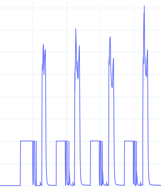
Recorded the voltage between tip and work piece during some 5 minutes. Was cutting a bunch of small holes.
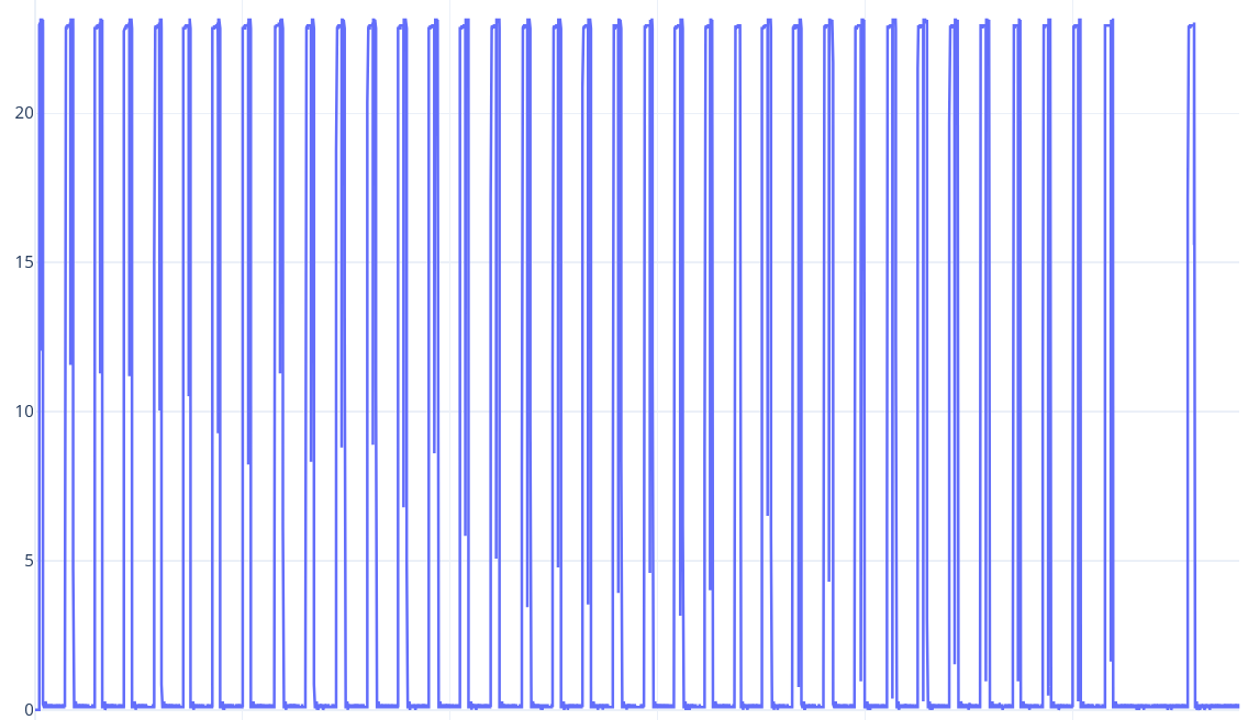
They all look like this one, with some variation.
This was on a dry work piece. There is a clear voltage drop, somewhat slow, delayed recovery.
Triggered contact condition was a one-cycle voltage drop of 5 Volts.
They all look like this one, with some variation.
This was on a dry work piece. There is a clear voltage drop, somewhat slow, delayed recovery.
Triggered contact condition was a one-cycle voltage drop of 5 Volts.
Attachments:
The following user(s) said Thank You: tommylight
Please Log in or Create an account to join the conversation.
- Hakan
- Offline
- Platinum Member
-
Less
More
- Posts: 1317
- Thank you received: 453
15 Oct 2025 09:47 #336489
by Hakan
Replied by Hakan on topic Ohmic sensing with IPTM-60
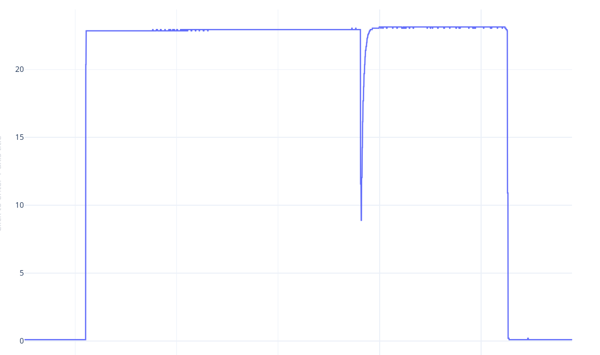
And here are voltages on a wet table.
Ok, little bit more intriguing than I first thought.
Not much of a dip there.
How to detect that? There are ways of course.
Ok, little bit more intriguing than I first thought.
Not much of a dip there.
How to detect that? There are ways of course.
Attachments:
Please Log in or Create an account to join the conversation.
- Hakan
- Offline
- Platinum Member
-
Less
More
- Posts: 1317
- Thank you received: 453
18 Oct 2025 08:24 #336649
by Hakan
Replied by Hakan on topic Ohmic sensing with IPTM-60
Learned something new there.
Note to self: When saying measure voltage on the work piece, then DON'T MEASURE THROUGH THE PLASMA CUTTER, MEASURE ON THE WORK PIECE.
I now did that and got the best voltage reading ever, never been that good.
The thing is that the first cut or sensing probe works fine, after that the machine does something internally with the voltage that ruins the coming sensing probes. Just got to measure the tip-work piece voltage closer to the work piece and it should work much much better.
I now get the cutting voltage into this voltage reader as well.
I'll see what I do with that, it doesn't hurt it in any way. Maybe I can take away the other voltage reader since I obviously now have two arc voltage readers.
Attachments:
Please Log in or Create an account to join the conversation.
- Hakan
- Offline
- Platinum Member
-
Less
More
- Posts: 1317
- Thank you received: 453
18 Oct 2025 15:53 #336664
by Hakan
Replied by Hakan on topic Ohmic sensing with IPTM-60
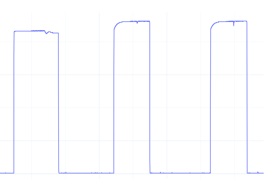
But why is there a double sense always?
It should be enough with one, the first contact.
The plots are from a web csv plot tool, output from the sampler component to record longer sequences.
The following settings have been used.
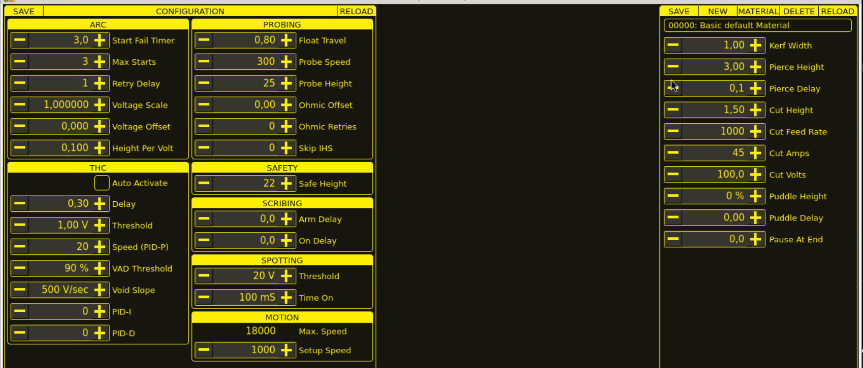
It should be enough with one, the first contact.
The plots are from a web csv plot tool, output from the sampler component to record longer sequences.
The following settings have been used.
Attachments:
Please Log in or Create an account to join the conversation.
- Hakan
- Offline
- Platinum Member
-
Less
More
- Posts: 1317
- Thank you received: 453
18 Oct 2025 19:33 #336666
by Hakan
Replied by Hakan on topic Ohmic sensing with IPTM-60
It was the probe height setting. Increasing the probe height setting a lot made it work with one touch.
Looks ok now.
Looks ok now.
Attachments:
The following user(s) said Thank You: tommylight, Clive S
Please Log in or Create an account to join the conversation.
- Hakan
- Offline
- Platinum Member
-
Less
More
- Posts: 1317
- Thank you received: 453
20 Oct 2025 15:15 - 20 Oct 2025 17:15 #336751
by Hakan
Replied by Hakan on topic Ohmic sensing with IPTM-60
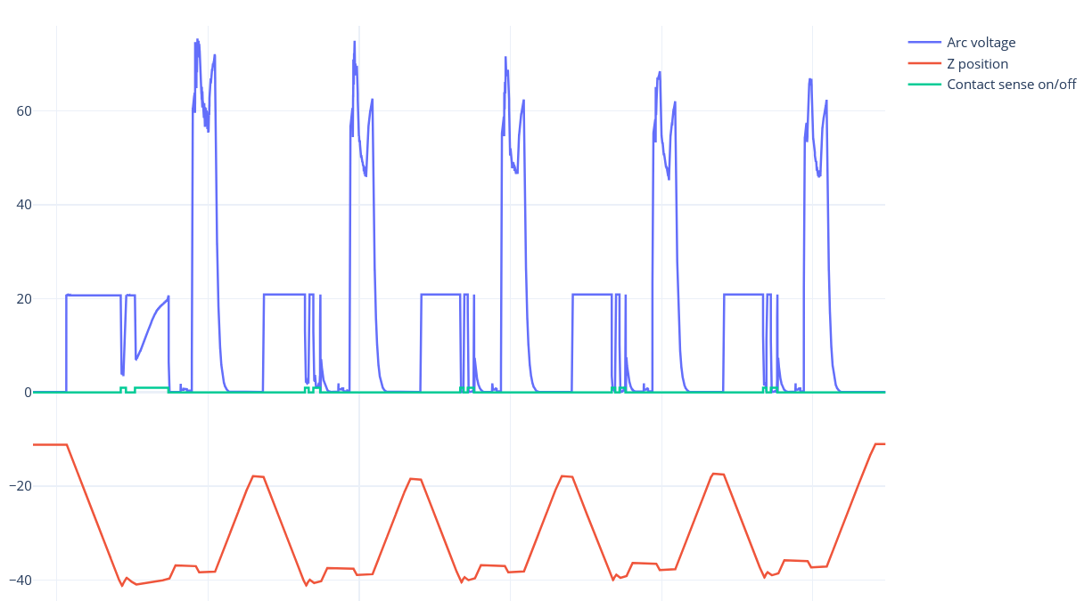
I made a detailed study of the probing.
I didn't quite understand it. Here is a detailed contact.
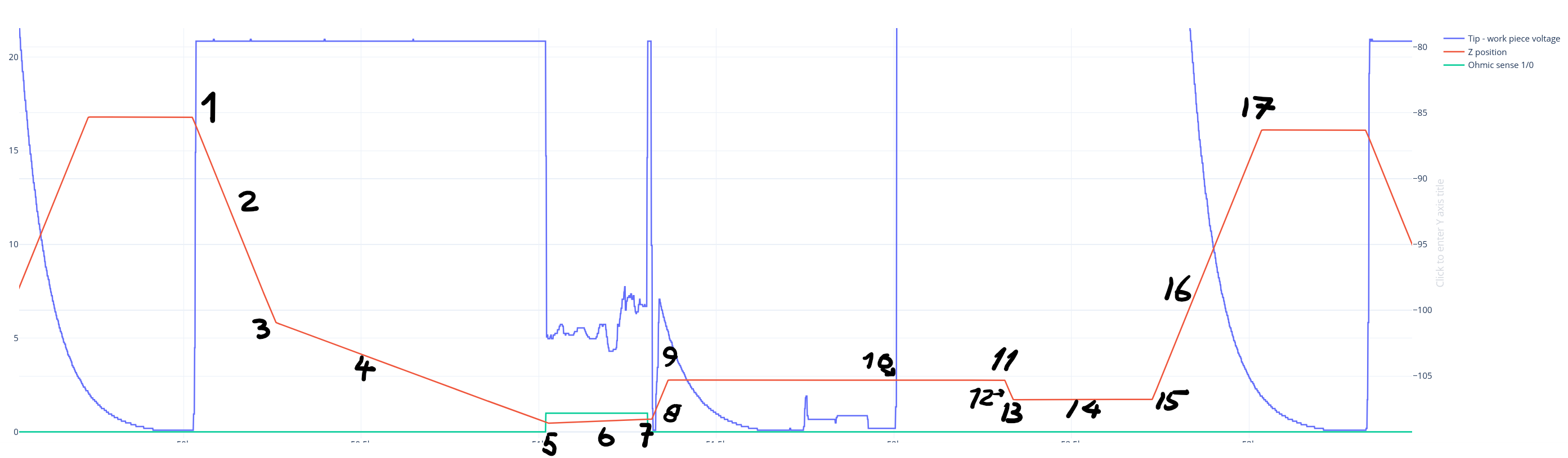
1. Start at the current position
2. Probe down with Z axle's max velocity (4000 mm/min)
3. Probe Height
4. Run with Probe Speed (600 mm/min)
5. Contact (voltage lower than limit). Brake with Z's max acceleration
6. Go up at 1 micrometer / cycle
7. Contact release (voltage higher than limit). This sets the material height.
8. Go up with Z axle's max velocity
9. Pierce height (measured from the new material height)
10. Piercing starts (voltage goes high) after 0.6 secs?.
11. Pierce Delay seconds after Pierce start
12. Go down with Z axle's max velocity
13. Cut Height
14. Cut for 5 mm at cut speed.
15. Arc has stopped.
16. Go up with Z axle's max velocity
17. Safe Height
The big take-away from this is that the material height is set when the probe goes up.
Focusing on contact criteria is not the right way.
Focus on non-contact criterium.
Also, to reduce the sensing time, one wants to
- have probe height close to the material
- use not very high probing speed, because of the distance before Z can stop
- use insanely high acceleration on Z
one gets punished by the probe-up speed being only 1 um/cycle.
Overshooting a few mm, which can happen with too high probe speed and low acceleration takes a few seconds to come back from.
I also wonder about the current method to set material height on probe-up.
Admittedly I have only looked at a few hundred contacts so I have not seen everything.
But what I have seen is that contact is consistently found and non-contact, release from contact is more hesitant.
For example here is a contact where the tip went into a water puddle on the table.
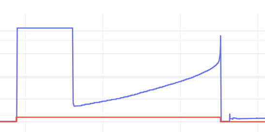
It failed to register ohmic sensing contact on probe-up. Would have had no problem to register the contact.
I can see it makes sense for the float switch to register material height on probe-up.
For ohmic sensing I think it is more straight-forward to register material height on probe-down.
I'll see if I can find my way in the plasma.comp code and make this mod and see how that works.
I didn't quite understand it. Here is a detailed contact.
1. Start at the current position
2. Probe down with Z axle's max velocity (4000 mm/min)
3. Probe Height
4. Run with Probe Speed (600 mm/min)
5. Contact (voltage lower than limit). Brake with Z's max acceleration
6. Go up at 1 micrometer / cycle
7. Contact release (voltage higher than limit). This sets the material height.
8. Go up with Z axle's max velocity
9. Pierce height (measured from the new material height)
10. Piercing starts (voltage goes high) after 0.6 secs?.
11. Pierce Delay seconds after Pierce start
12. Go down with Z axle's max velocity
13. Cut Height
14. Cut for 5 mm at cut speed.
15. Arc has stopped.
16. Go up with Z axle's max velocity
17. Safe Height
The big take-away from this is that the material height is set when the probe goes up.
Focusing on contact criteria is not the right way.
Focus on non-contact criterium.
Also, to reduce the sensing time, one wants to
- have probe height close to the material
- use not very high probing speed, because of the distance before Z can stop
- use insanely high acceleration on Z
one gets punished by the probe-up speed being only 1 um/cycle.
Overshooting a few mm, which can happen with too high probe speed and low acceleration takes a few seconds to come back from.
I also wonder about the current method to set material height on probe-up.
Admittedly I have only looked at a few hundred contacts so I have not seen everything.
But what I have seen is that contact is consistently found and non-contact, release from contact is more hesitant.
For example here is a contact where the tip went into a water puddle on the table.
It failed to register ohmic sensing contact on probe-up. Would have had no problem to register the contact.
I can see it makes sense for the float switch to register material height on probe-up.
For ohmic sensing I think it is more straight-forward to register material height on probe-down.
I'll see if I can find my way in the plasma.comp code and make this mod and see how that works.
Attachments:
Last edit: 20 Oct 2025 17:15 by Hakan.
The following user(s) said Thank You: tommylight
Please Log in or Create an account to join the conversation.
- Hakan
- Offline
- Platinum Member
-
Less
More
- Posts: 1317
- Thank you received: 453
20 Oct 2025 20:14 - 20 Oct 2025 20:16 #336772
by Hakan
Replied by Hakan on topic Ohmic sensing with IPTM-60
Yes, that really made a difference! Much more distinct and quicker too.
I wonder if there is a way to upload a short video? All kinds of pictures are possible, yes, but a video?
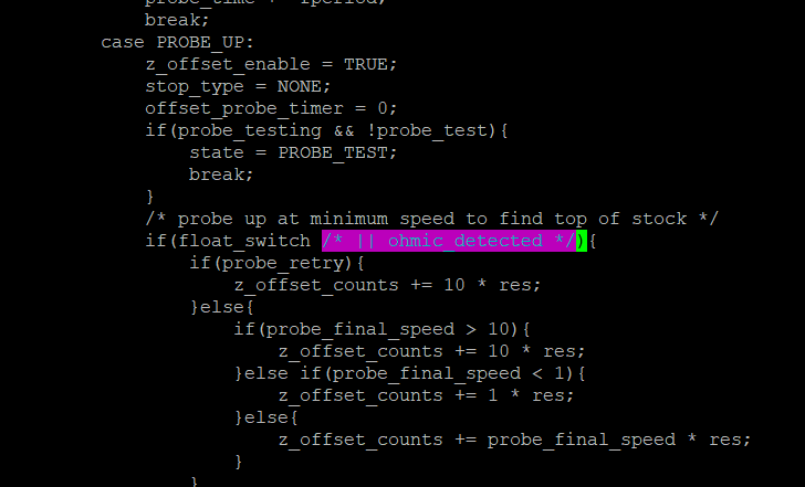
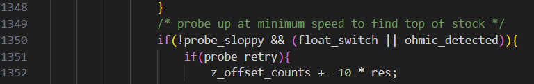
Here is the only change I made in plasmac.comp.
It made plasmac skip the PROBE_UP sequence for the ohmic probe.
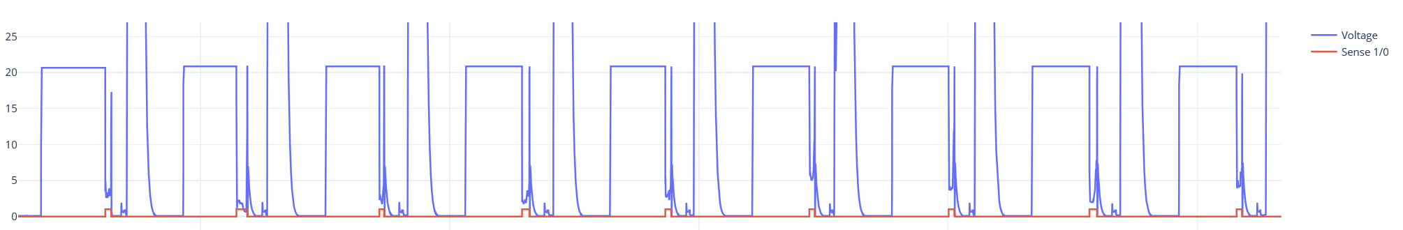
Ten 5 mm cuts in 1 mm sheet including probing before the cuts.
It goes down, contact detected and directly up to pierce height and starts the cuts.
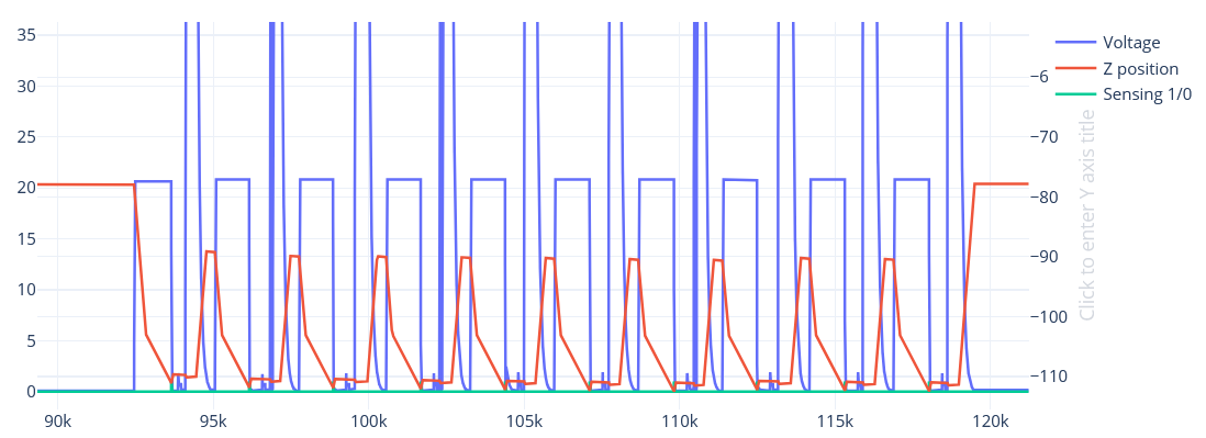
I like this!
I wonder if there is a way to upload a short video? All kinds of pictures are possible, yes, but a video?
Here is the only change I made in plasmac.comp.
It made plasmac skip the PROBE_UP sequence for the ohmic probe.
Ten 5 mm cuts in 1 mm sheet including probing before the cuts.
It goes down, contact detected and directly up to pierce height and starts the cuts.
I like this!
Attachments:
Last edit: 20 Oct 2025 20:16 by Hakan.
The following user(s) said Thank You: tommylight
Please Log in or Create an account to join the conversation.
- tommylight
-

- Away
- Moderator
-

Less
More
- Posts: 21633
- Thank you received: 7388
20 Oct 2025 20:47 #336773
by tommylight
Someone insisted on "precise" pierce height to 0.1mm, for something that does not care even being a full mm off.
Replied by tommylight on topic Ohmic sensing with IPTM-60
So do i, for float switch also, but i digress as i did complain when PlasmaC was developed about double probing being a waste of time.I like this!
Someone insisted on "precise" pierce height to 0.1mm, for something that does not care even being a full mm off.
Please Log in or Create an account to join the conversation.
- Hakan
- Offline
- Platinum Member
-
Less
More
- Posts: 1317
- Thank you received: 453
21 Oct 2025 06:54 #336803
by Hakan
Replied by Hakan on topic Ohmic sensing with IPTM-60
Better than that, the component is aiming for 1 micrometer precision on the material height.
I guess there are good reasons for doing it the way it is done, I wasn't around when the plasma component was developed.
Doing the probing the same way, and calibrating the results using ProbeTest give me the precision I need and more.
It's a pity, I liked the linuxcnc version from apt, but now I will use my own version with probing on probe down.
It could be easily fixed with two lines of code, one to define a new pin and one to modify the "if" statement

Since you've already taken on the fight and lost, I'll leave it here.
I guess there are good reasons for doing it the way it is done, I wasn't around when the plasma component was developed.
Doing the probing the same way, and calibrating the results using ProbeTest give me the precision I need and more.
It's a pity, I liked the linuxcnc version from apt, but now I will use my own version with probing on probe down.
It could be easily fixed with two lines of code, one to define a new pin and one to modify the "if" statement
Since you've already taken on the fight and lost, I'll leave it here.
Attachments:
Please Log in or Create an account to join the conversation.
- Hakan
- Offline
- Platinum Member
-
Less
More
- Posts: 1317
- Thank you received: 453
21 Oct 2025 08:00 - 21 Oct 2025 08:13 #336805
by Hakan
Replied by Hakan on topic Ohmic sensing with IPTM-60
Video
Last edit: 21 Oct 2025 08:13 by Hakan.
Please Log in or Create an account to join the conversation.
Time to create page: 0.610 seconds