- Configuring LinuxCNC
- Advanced Configuration
- Developments on my Home built 5C CNC Lathe - Polar interp. and Live tooling
Developments on my Home built 5C CNC Lathe - Polar interp. and Live tooling
- spumco
- Offline
- Platinum Member
-

Less
More
- Posts: 2126
- Thank you received: 882
18 Dec 2023 13:14 - 18 Dec 2023 13:28 #288481
by spumco
I was mistaken. The post does, in fact, use the polar interpolation function in the control. Mea culpa.
NoJo,
No worries, COHAL wasn't specific.
The PP is a text file, and the post dialect is specific to F360 and other Autodesk products. If you're interested in the post you can open it up in any text editor and poke around.
If you're really, really interested, you can use some tools to see exactly what parts of the post are responsible for sections of the g-code output file. To this end, there are a couple of plug-ins available for Visual Studio Code which work with F360 posts.
Those plugins let you export a raw 'dump' file from F360, run it through the PP inside VS Code, and present you with a split-screen. One side is the PP file, the other is the g-code output. The magic is that when you click/select a section of g-code, the part of the PP file responsible for generating that g-code is automatically highlighted. Makes post editing (and reverse-engineering) much easier.
NYCCNC's covered this process in one of their YT videos, as have a number of other YT channels.
Of course, you'll need F360 installed to do this, but the free version works fine. And XZC movements are only 3-axis - no need for paid 4/5 axis manufacturing extensions. I understand & sympathize with your reluctance to get involved with F360 (and other subscription-based software), but if you're interested in the post it won't cost you anything to have a go at it.
If you (or anyone else) has a look in the post you'll actually find some sections which deal with polar interpolation. I believe this post was recycled by the author and modified to suit my lathe control... not written from scratch. My inexpert review of the post has discovered some sections which are pretty clearly not specific to my control (i.e. subspindle) so I think the polar interp is a leftover. There is no circular interp in the post matching my control (G7.1), yet radial milling still works... reinforcing my suspicion that F360 and the post are handling axial/radial milling operations without triggering the control's polar/radial interpolation modes.
Replied by spumco on topic Developments on my Home built 5C CNC Lathe - Polar interp. and Live tooling
EDITSorry re the confusion - As I had started this topic and COHAL's post did not address anyone specific ( that I can see) , I thought it was meant for me..
I wonder how that PP works in milling - it must do all the polar interp itself and output thousands of small moves to all the axis to follow a polar path in cartesian fashion. How is the PP written? Do you have source code?
I was mistaken. The post does, in fact, use the polar interpolation function in the control. Mea culpa.
NoJo,
No worries, COHAL wasn't specific.
The PP is a text file, and the post dialect is specific to F360 and other Autodesk products. If you're interested in the post you can open it up in any text editor and poke around.
If you're really, really interested, you can use some tools to see exactly what parts of the post are responsible for sections of the g-code output file. To this end, there are a couple of plug-ins available for Visual Studio Code which work with F360 posts.
Those plugins let you export a raw 'dump' file from F360, run it through the PP inside VS Code, and present you with a split-screen. One side is the PP file, the other is the g-code output. The magic is that when you click/select a section of g-code, the part of the PP file responsible for generating that g-code is automatically highlighted. Makes post editing (and reverse-engineering) much easier.
NYCCNC's covered this process in one of their YT videos, as have a number of other YT channels.
Of course, you'll need F360 installed to do this, but the free version works fine. And XZC movements are only 3-axis - no need for paid 4/5 axis manufacturing extensions. I understand & sympathize with your reluctance to get involved with F360 (and other subscription-based software), but if you're interested in the post it won't cost you anything to have a go at it.
Last edit: 18 Dec 2023 13:28 by spumco.
Please Log in or Create an account to join the conversation.
- spumco
- Offline
- Platinum Member
-
Less
More
- Posts: 2126
- Thank you received: 882
18 Dec 2023 13:36 #288485
by spumco
Replied by spumco on topic Developments on my Home built 5C CNC Lathe - Polar interp. and Live tooling
Egg on my face to anyone reading this. It's been a while since I've used live tooling on my lathe and I simply forgot how the post works.
Yes, the post DOES invoke polar interpolation in the control... meaning if anyone wants an LCNC post (based on my post) with C-axis milling they will have to use some sort of polar interpolation switchkins.
Here's a section of axial milling I just dug up:
(2D Adaptive1)
N130 M1
N135 G90 G94 G18 G80
N140 T0101
N145 M52
N150 G97 S4000 M13
N155 M9
N160 G0 C0.
N165 G12.1
N170 G1 Z0.575 F230.
N175 X1.1179 C-0.1664
N180 Z-0.375
N185 Z-0.385 F16.
N190 X1.1178 Z-0.3859
N195 X1.1176 Z-0.3867
N200 X1.1172 C-0.1663 Z-0.3876
N205 X1.1167 C-0.1662 Z-0.3884
N210 X1.1161 Z-0.3892
N215 X1.1153 C-0.1661 Z-0.39
N220 X1.1144 C-0.1659 Z-0.3907
N225 X1.1133 C-0.1658 Z-0.3914
N230 X1.1122 C-0.1657 Z-0.3921
N235 X1.111 C-0.1655 Z-0.3927
N240 X1.1096 C-0.1653 Z-0.3932
N245 X1.1082 C-0.1652 Z-0.3937
N250 X1.1067 C-0.165 Z-0.3941
N255 X1.1051 C-0.1648 Z-0.3944
N260 X1.1035 C-0.1646 Z-0.3947
N265 X1.1019 C-0.1643 Z-0.3948
N270 X1.1002 C-0.1641 Z-0.395
N275 X1.0985 C-0.1639
N280 G3 X0.8263 C-0.1443 I-0.1584 J-0.6183
N285 G1 X0.8255
N290 G3 X0.7362 C-0.1986 I0.1376 J-0.1587
N295 G2 X0.685 C-0.2357 I-0.121 J0.0562
N300 X0.1857 C-0.3953 I-0.3739 J0.3096
N305 G3 X0.1122 C-0.4059 I0.0071 J-0.0939
N310 G1 X0.1086 C-0.4071
NOTES:
Yes, the post DOES invoke polar interpolation in the control... meaning if anyone wants an LCNC post (based on my post) with C-axis milling they will have to use some sort of polar interpolation switchkins.
Here's a section of axial milling I just dug up:
Warning: Spoiler!
(2D Adaptive1)
N130 M1
N135 G90 G94 G18 G80
N140 T0101
N145 M52
N150 G97 S4000 M13
N155 M9
N160 G0 C0.
N165 G12.1
N170 G1 Z0.575 F230.
N175 X1.1179 C-0.1664
N180 Z-0.375
N185 Z-0.385 F16.
N190 X1.1178 Z-0.3859
N195 X1.1176 Z-0.3867
N200 X1.1172 C-0.1663 Z-0.3876
N205 X1.1167 C-0.1662 Z-0.3884
N210 X1.1161 Z-0.3892
N215 X1.1153 C-0.1661 Z-0.39
N220 X1.1144 C-0.1659 Z-0.3907
N225 X1.1133 C-0.1658 Z-0.3914
N230 X1.1122 C-0.1657 Z-0.3921
N235 X1.111 C-0.1655 Z-0.3927
N240 X1.1096 C-0.1653 Z-0.3932
N245 X1.1082 C-0.1652 Z-0.3937
N250 X1.1067 C-0.165 Z-0.3941
N255 X1.1051 C-0.1648 Z-0.3944
N260 X1.1035 C-0.1646 Z-0.3947
N265 X1.1019 C-0.1643 Z-0.3948
N270 X1.1002 C-0.1641 Z-0.395
N275 X1.0985 C-0.1639
N280 G3 X0.8263 C-0.1443 I-0.1584 J-0.6183
N285 G1 X0.8255
N290 G3 X0.7362 C-0.1986 I0.1376 J-0.1587
N295 G2 X0.685 C-0.2357 I-0.121 J0.0562
N300 X0.1857 C-0.3953 I-0.3739 J0.3096
N305 G3 X0.1122 C-0.4059 I0.0071 J-0.0939
N310 G1 X0.1086 C-0.4071
NOTES:
- G12.1 Polar Coordinate Interpolation ON
- M52 C-axis ON
- This disables the main spindle motor
- Fires an air cylinder which forces the C-axis stepper in contact with the spindle bull gear
- Homes the (now) C-axis using the spindle-mounted encoder.
- M13 live tool ON, clockwise
The following user(s) said Thank You: tommylight
Please Log in or Create an account to join the conversation.
- COFHAL
- Offline
- Platinum Member
-
Less
More
- Posts: 455
- Thank you received: 61
18 Dec 2023 19:55 #288511
by COFHAL
Replied by COFHAL on topic Developments on my Home built 5C CNC Lathe - Polar interp. and Live tooling
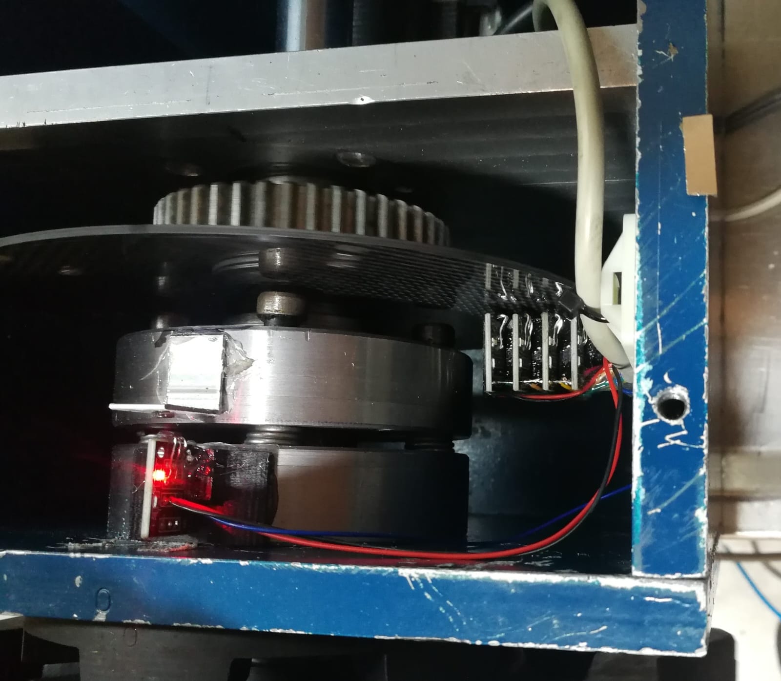
In that sense you are wrong, the carousel component does not do what you say, it rotates until it finds the selected tool through the sensors installed in the ATC, as you can see in the attached video. I used hall sensors configured as gray code, not binary, which are activated by contact with magnets installed on a disk that rotates with the tool changer. I also used a stepper motor but configured in speed mode. And I was careful to install another hall sensor that detects when the turret is unlocked and also another sensor to detect low air pressure and through an AND activate the stepgen that controls the ATC engine motor. I did all the implementation with the help of Andy, who developed this component and as he himself indicated to me, for a lathe the implementation was simpler than for a milling machine.
A live tool was also installed, but since the turret was already built, it was decided to use one of the tool pockets to install it using a coupler that disengages from the live tool motor when the turret is activated by the pneumatic piston, this is Taken from a YouTube video of someone who implemented it like this and who also uses LCN
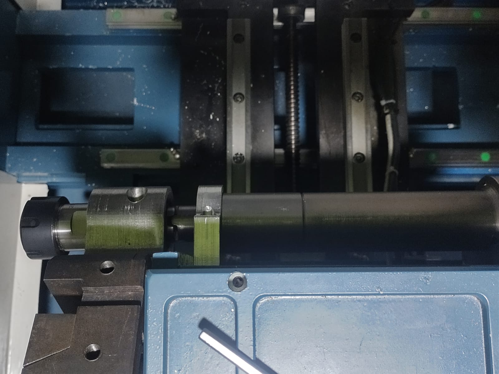
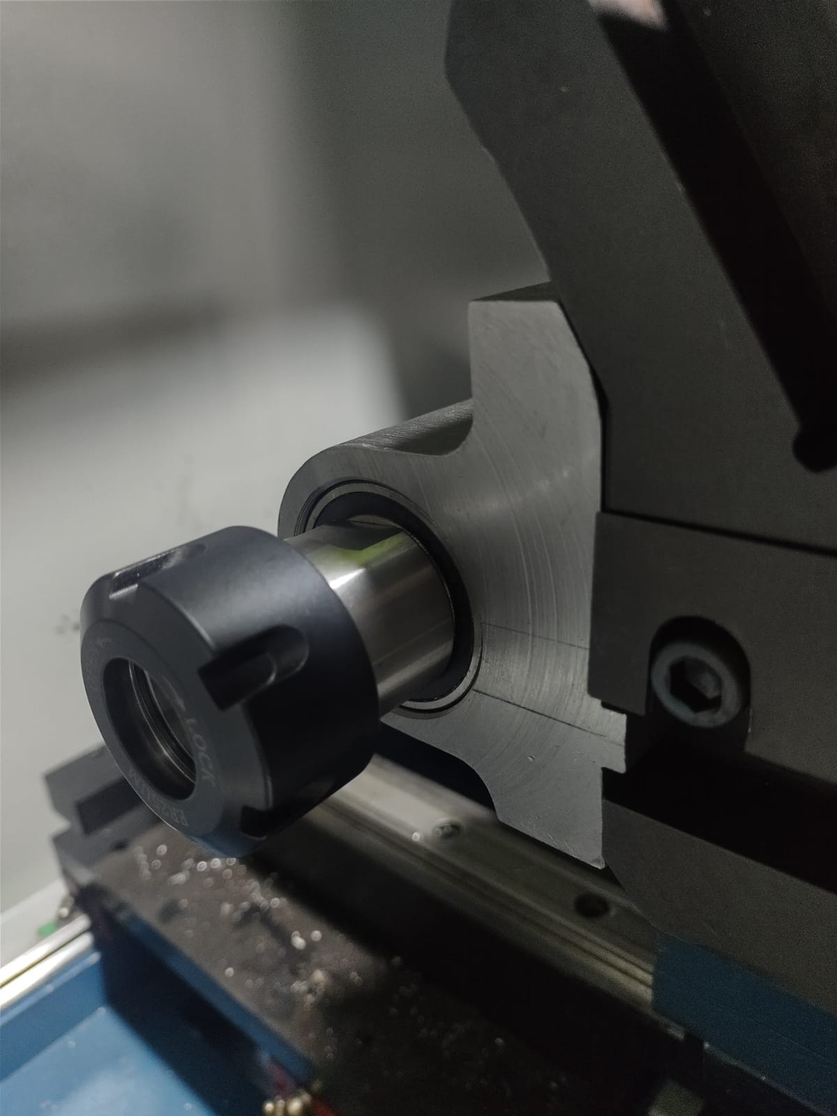
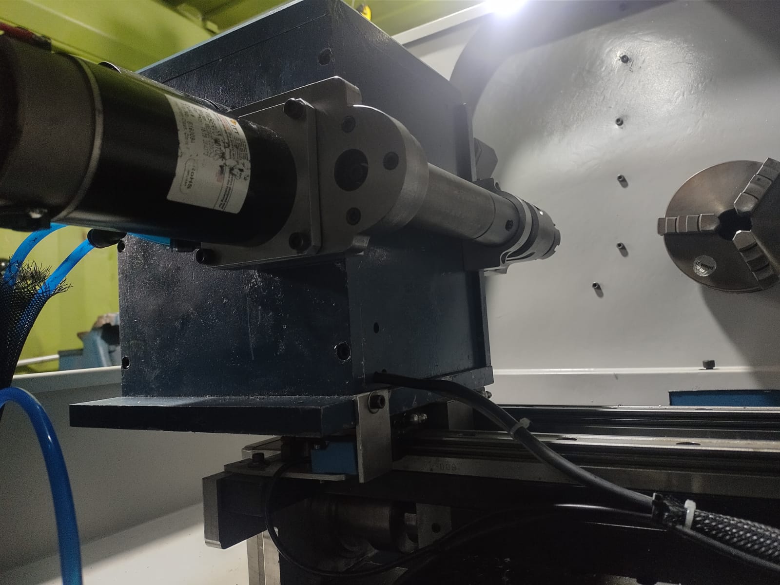
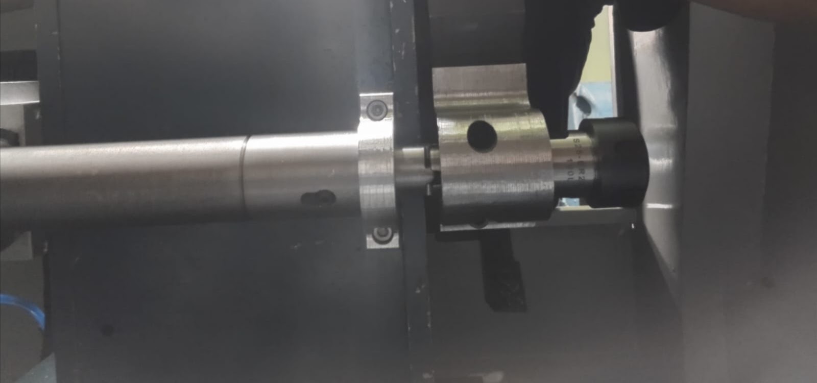
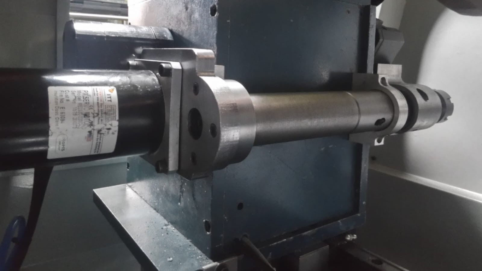
A live tool was also installed, but since the turret was already built, it was decided to use one of the tool pockets to install it using a coupler that disengages from the live tool motor when the turret is activated by the pneumatic piston, this is Taken from a YouTube video of someone who implemented it like this and who also uses LCN
Attachments:
The following user(s) said Thank You: besriworld
Please Log in or Create an account to join the conversation.
- COFHAL
- Offline
- Platinum Member
-
Less
More
- Posts: 455
- Thank you received: 61
18 Dec 2023 20:00 #288513
by COFHAL
Replied by COFHAL on topic Developments on my Home built 5C CNC Lathe - Polar interp. and Live tooling
Dear spumco
Thank you for your contributions and for sharing the post-processing.r
Thank you for your contributions and for sharing the post-processing.r
The following user(s) said Thank You: tommylight, spumco, edimas93
Please Log in or Create an account to join the conversation.
- spumco
- Offline
- Platinum Member
-
Less
More
- Posts: 2126
- Thank you received: 882
19 Dec 2023 04:39 #288543
by spumco
Replied by spumco on topic Developments on my Home built 5C CNC Lathe - Polar interp. and Live tooling
NoJo,
I've installed caxis.comp and gn_userkins.comp and edited my HAL and INI files. After a couple of typo corrections LCNC starts up with no errors.
NOTE - I renamed gn_userkins.comp to polar_userkins.comp, and edited all the files/pins that refer to gn_userkins. No offense intended, but 'polar' helps me remember what stuff is doing.
I can see all the caxis pins in halshow, and I can watch caxis.0.state change from 0 to 2 and back when I start/stop the spindle (M3/M5). So the spindle still works - yay!
First hurdle... homing.
When I try to home C-axis, the spindle just rotates at about 60rpm until the f-error piles up. Nothing seems to be setting the index-enable pin, so it doesn't stop. Once it errors the machine turns off (in software), and if I turn it back on it resumes the homing attempt.
I've got HOME_USE_INDEX = 1 in INI, and if I unlink & set index-enable = true I can watch the index pulse trigger. So nothing really dumb like a faulty index signal from the encoder.
Any ideas where to start troubleshooting? spindle HAL and INI attached.
Thx,
R
The following user(s) said Thank You: besriworld
Please Log in or Create an account to join the conversation.
- besriworld
- Offline
- Elite Member
-

Less
More
- Posts: 315
- Thank you received: 84
22 May 2025 16:37 #328925
by besriworld
Replied by besriworld on topic Developments on my Home built 5C CNC Lathe - Polar interp. and Live tooling
It seems quite complicated. Has anyone done it with +-10v control? I want to try it on my lathe.
Please Log in or Create an account to join the conversation.
- spumco
- Offline
- Platinum Member
-
Less
More
- Posts: 2126
- Thank you received: 882
22 May 2025 16:50 #328926
by spumco
It's been a while since that post, and my lathe project has been stalled for a few months... but I had to give up on C-axis.comp. I didn't get far enough to try the polar kinematics.
The insurmountable problem I encountered with caxis.comp was that it interfered with synchronized spindle moves (threading). I wasn't able to figure out how/why it was causing problems, but once I abandoned it for a spindle/axis scheme proposed by @Aciera and @PCW, threading started working properly.
There is still an issue with threading in LCNC - thread start point varies with RPM - but that's not related to caxis.comp.
Replied by spumco on topic Developments on my Home built 5C CNC Lathe - Polar interp. and Live tooling
It seems quite complicated. Has anyone done it with +-10v control? I want to try it on my lathe.
It's been a while since that post, and my lathe project has been stalled for a few months... but I had to give up on C-axis.comp. I didn't get far enough to try the polar kinematics.
The insurmountable problem I encountered with caxis.comp was that it interfered with synchronized spindle moves (threading). I wasn't able to figure out how/why it was causing problems, but once I abandoned it for a spindle/axis scheme proposed by @Aciera and @PCW, threading started working properly.
There is still an issue with threading in LCNC - thread start point varies with RPM - but that's not related to caxis.comp.
The following user(s) said Thank You: besriworld
Please Log in or Create an account to join the conversation.
- besriworld
- Offline
- Elite Member
-
Less
More
- Posts: 315
- Thank you received: 84
22 May 2025 17:46 #328928
by besriworld
Replied by besriworld on topic Developments on my Home built 5C CNC Lathe - Polar interp. and Live tooling
Thanks for the update. Then I will try without polar coordinates.I would be happy if you could share the configuration. Because I did not find an example of a spindle and C axis with +-10v control.
My lathe doesn't have an index yet and can't make threads. Because I want to install a hydraulic chuck first.
My lathe doesn't have an index yet and can't make threads. Because I want to install a hydraulic chuck first.
Please Log in or Create an account to join the conversation.
- spumco
- Offline
- Platinum Member
-
Less
More
- Posts: 2126
- Thank you received: 882
22 May 2025 18:46 #328931
by spumco
Replied by spumco on topic Developments on my Home built 5C CNC Lathe - Polar interp. and Live tooling
I don't have copy on hand, but if you search through my posts you should find some of the later caxis.comp configs attached. Maybe 4-6 months ago or so?
I tried step/dir and pwm, so there may be examples of both attempts somewhere in the forum.
Something to keep in mind is that for rotary axis work you want the highest resolution encoder (or resolver) you can get. NoJo (OP) I think reported problems with C-axis milling and feature alignment due to a moderate-count encoder.
Of course, high counts and a high-speed spindle means problems with max input speed. I wound up with a 10k-line encoder on my 3500rpm spindle... which works but I had to turn off Mesa input filtering.
Another issue I think I encountered with NoJo's polar kinematics was that he hard-coded the live tool offset in to the component. He only had a single live tool so that worked for him, but a re-write which uses a tool offset from the tool table might be wise.
Please Log in or Create an account to join the conversation.
- besriworld
- Offline
- Elite Member
-
Less
More
- Posts: 315
- Thank you received: 84
22 May 2025 19:05 #328932
by besriworld
Replied by besriworld on topic Developments on my Home built 5C CNC Lathe - Polar interp. and Live tooling
At a later stage, I plan to add an additional 1kW servo motor, which will operate in torque mode to act as a dynamic load on the main 7kW motor. This will increase the system's rigidity. Currently, I'm using the encoder from the main motor
Please Log in or Create an account to join the conversation.
- Configuring LinuxCNC
- Advanced Configuration
- Developments on my Home built 5C CNC Lathe - Polar interp. and Live tooling
Time to create page: 0.309 seconds