linear scale and AC servo set up - sanity check
- chienMouille
- Offline
- Senior Member
-

Less
More
- Posts: 73
- Thank you received: 3
04 Oct 2022 16:09 #253455
by chienMouille
Replied by chienMouille on topic linear scale and AC servo set up - sanity check
RotarySMP, yes, the actual backlash of the acme screw which i still have is about 0.27mm. I just tried running with open loop and software backlash compensation. Doing a few back and forth this way gets me to within 0.02-0.05mm accuracy (repeatability), as per the DRO independently connected to the glass scales. I get that could be good enough for now and until I install actual ball screws. You think there is no way I fight this backlash with encoder scale feedback on the acme thread right?
Todd, yes, this is open loop with only the "feedback from the linear scale to "joint.N.motor-pos-fb" (keep the stepgen's position feedback connected to the PID loop)", as per your suggestion, or I guess how I understood to implement it in hal. Was that correct?
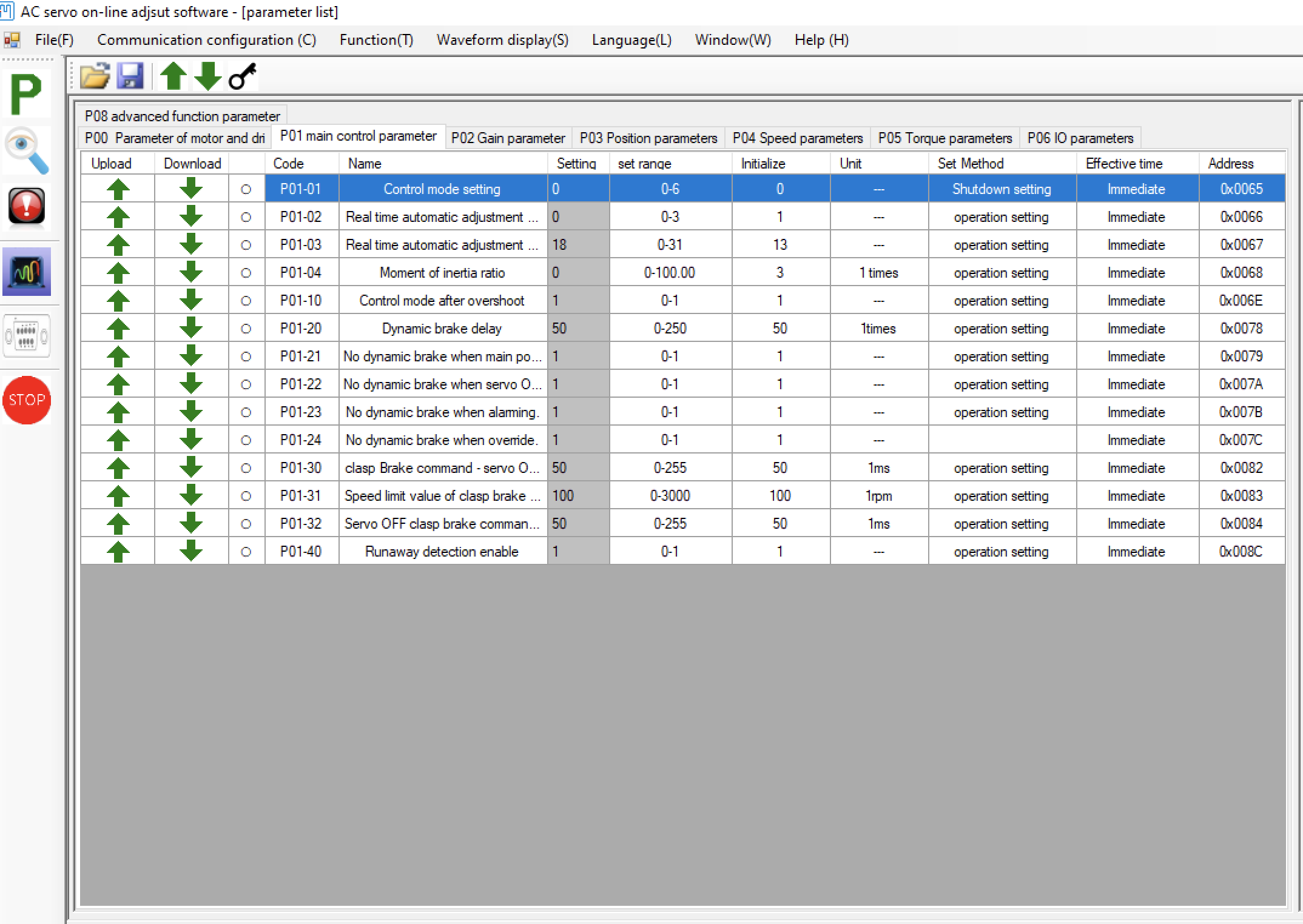
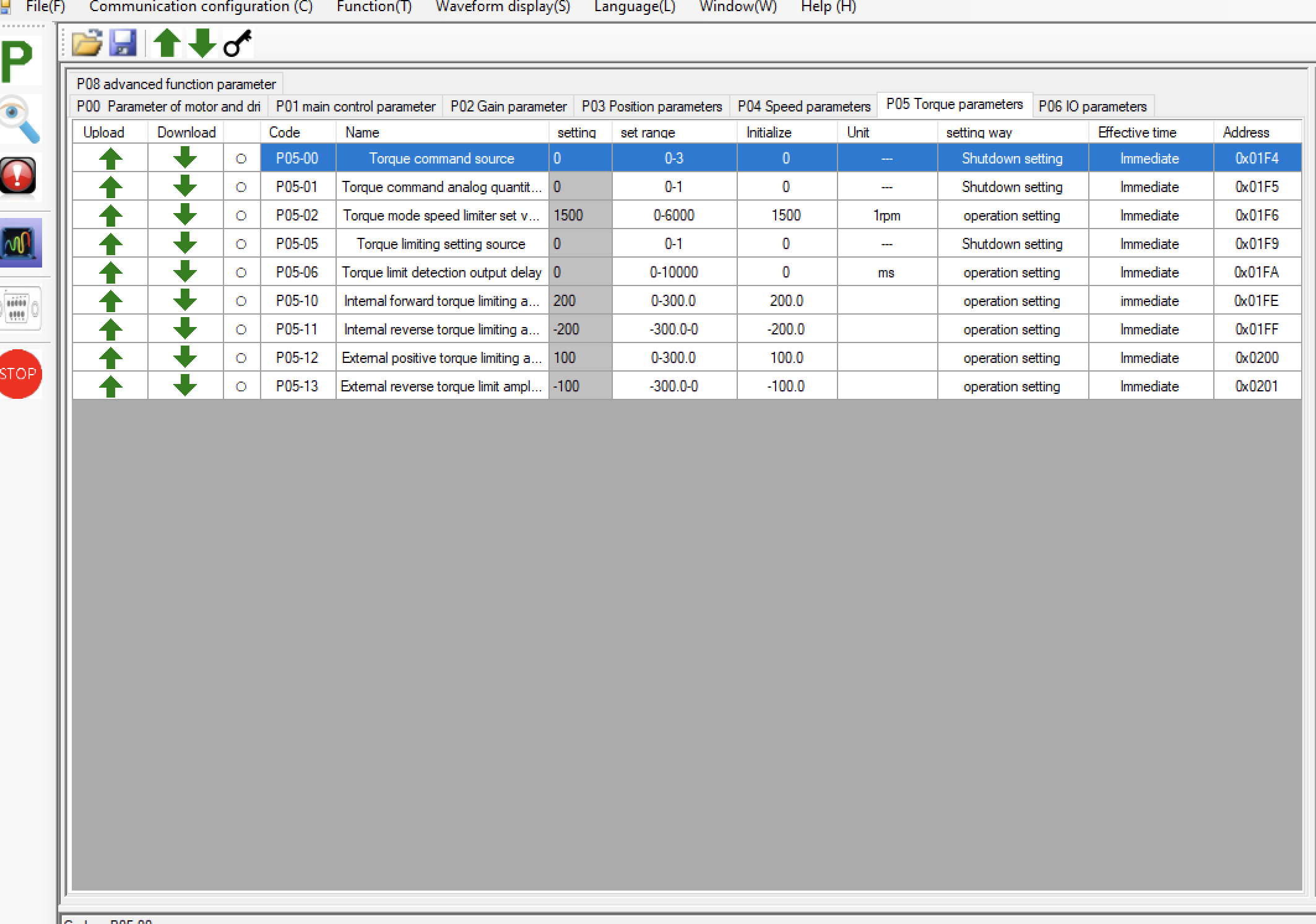
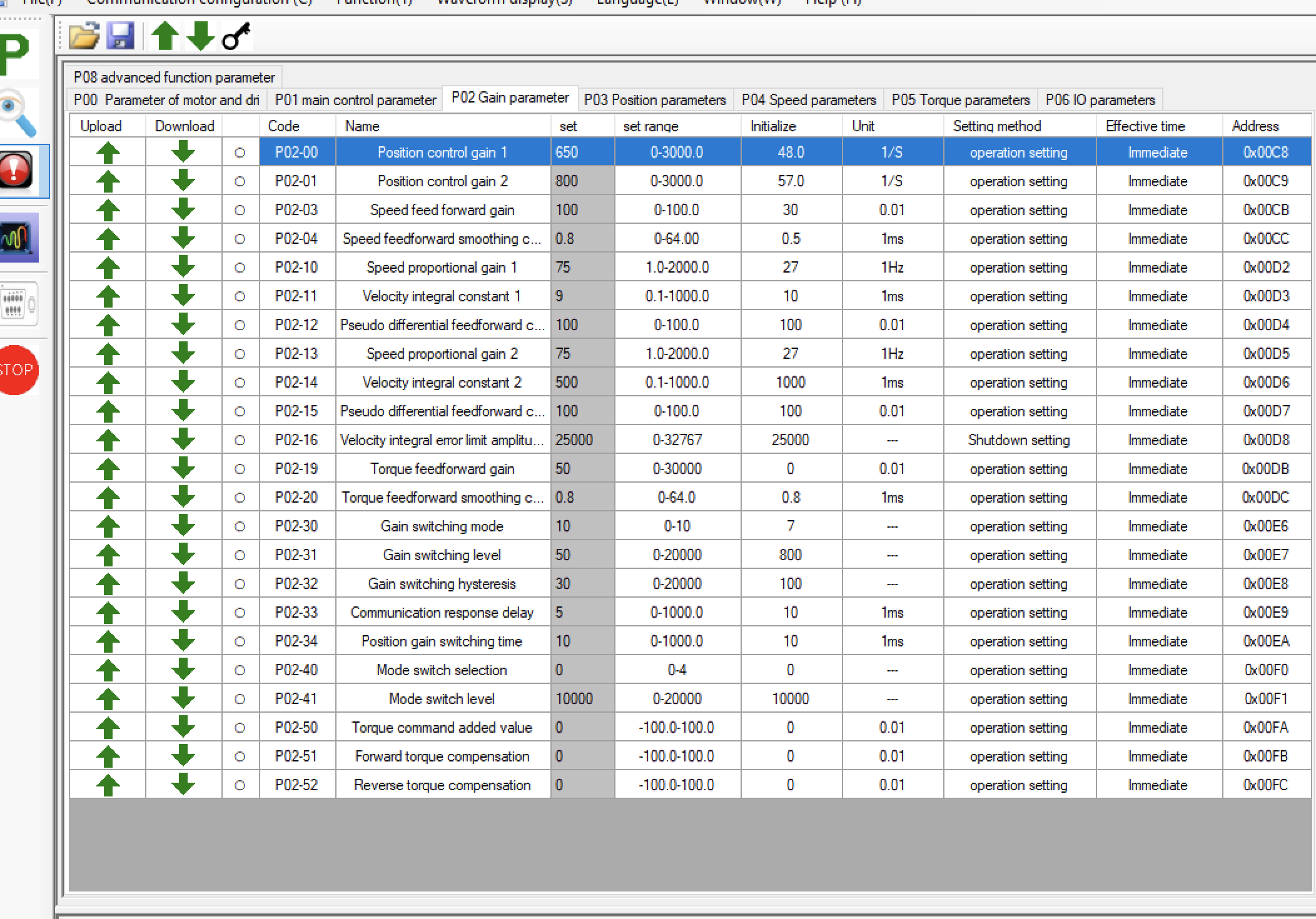
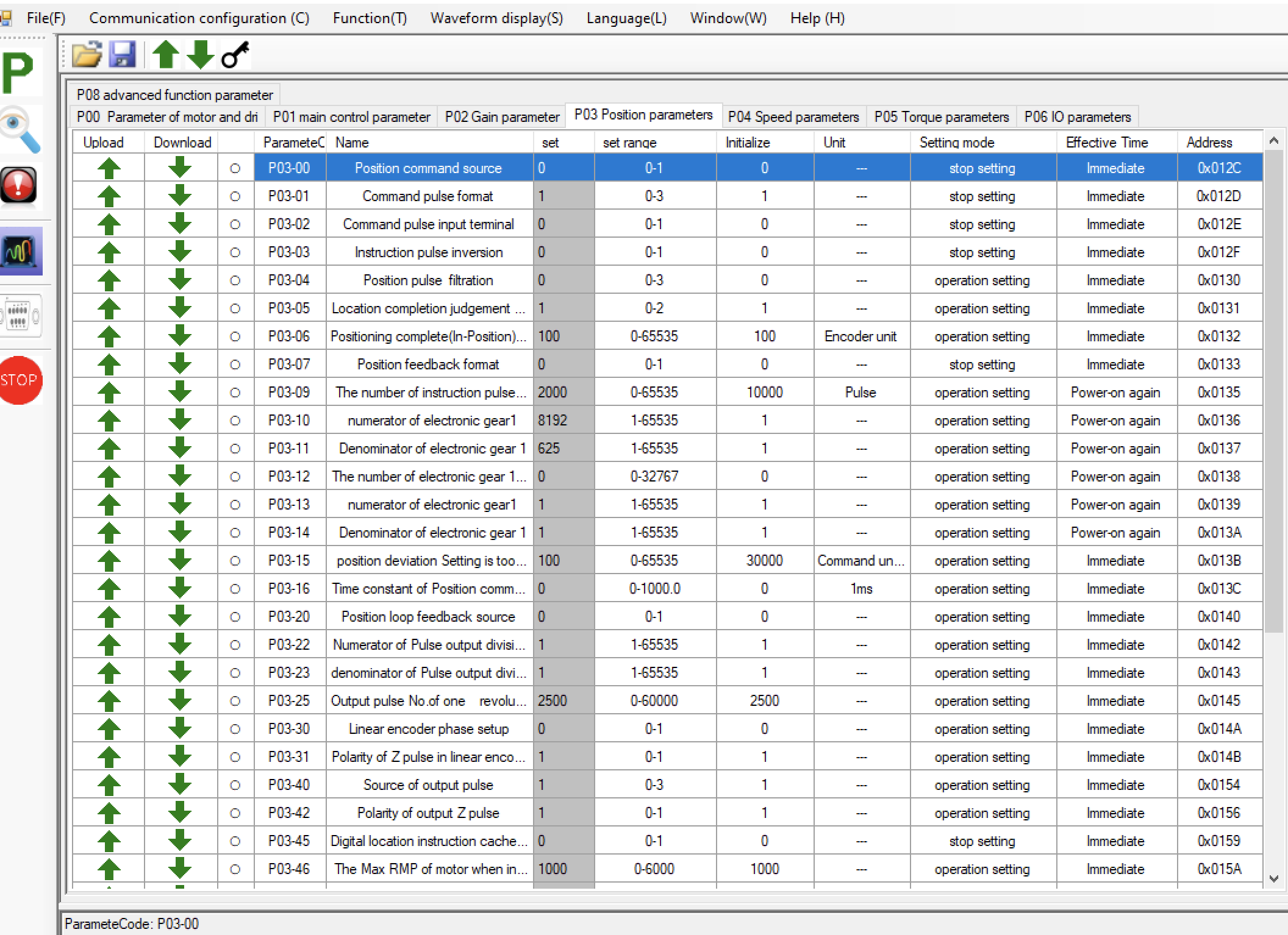
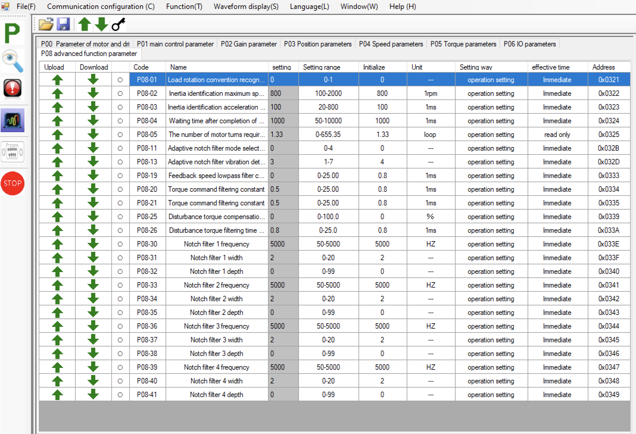
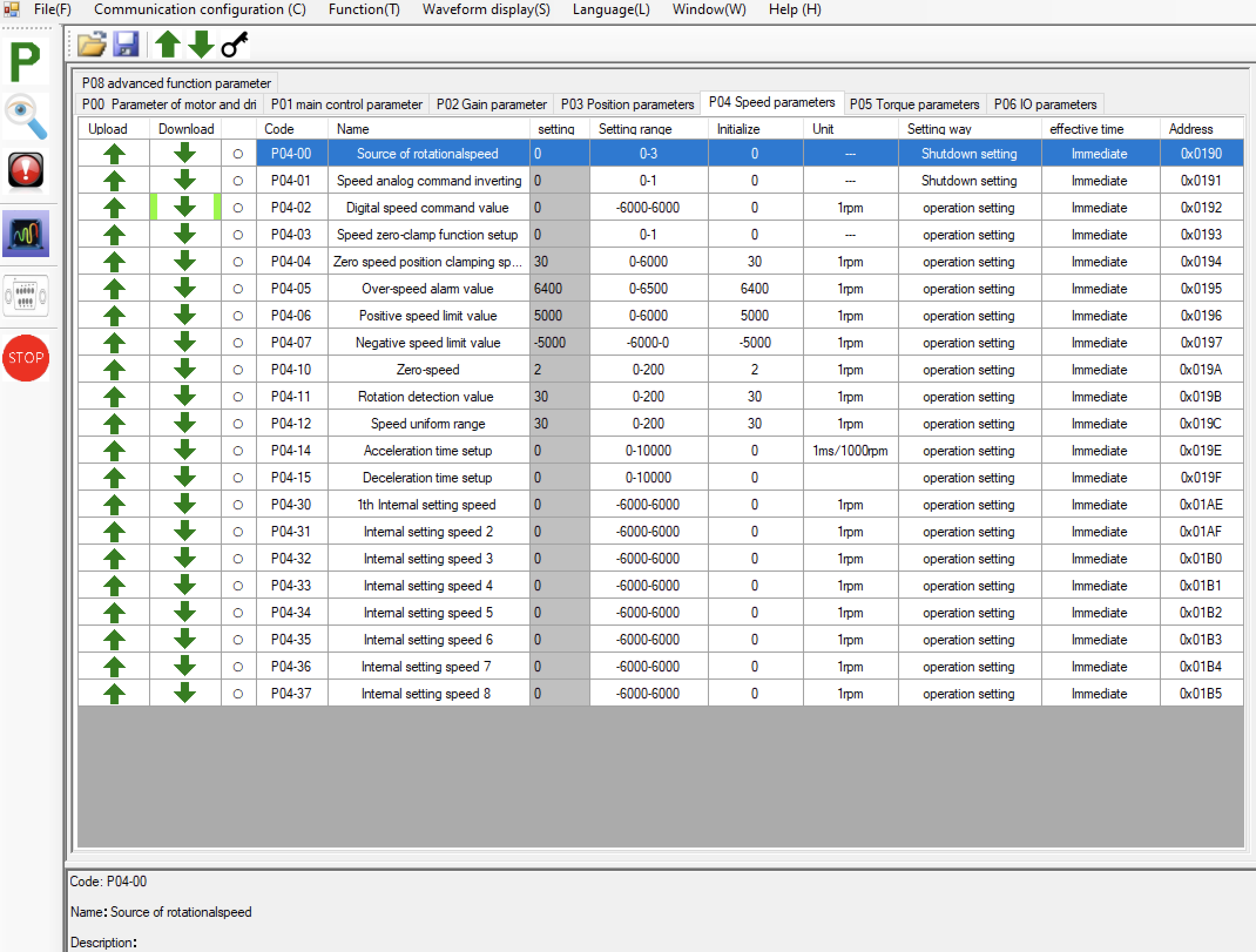
Here are some screenshots of the drive settings as I got them now. It's an AC 750W JMC servo. I mainly played with settings in the gain tab, mostly with the 3 first ones, which I understand as the P parameter. I'm not sure what the derivative would be here. It's pretty confusing. I also added a slight filtering in the advanced functions tab -> torque command filtering constant, to remove the last slight vibrations I had left. I also reduced the step amounts per revolution from 10000 to 2000, in order to be able to get a bit more velocity and acceleration out of LinuxCNC, I have a belt reduction between the motor and the axis of 2/3. Half a turn of the servo moves the table 1mm.
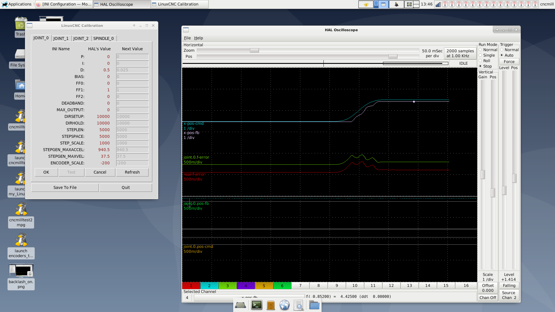
I also add a capture of the driver scopes. It shows a following error of +3 -3 units max at a speed of 1800mm/min. As I understand units are in encoder steps. If that is true and the encoder is 10000 per turn, then a millimeter movement of the table is 5000 units and so 3 units are under a micron following error.
Is that a problematic tuning? If so what would you change?
Thanks a lot I'm very new to this.

Todd, yes, this is open loop with only the "feedback from the linear scale to "joint.N.motor-pos-fb" (keep the stepgen's position feedback connected to the PID loop)", as per your suggestion, or I guess how I understood to implement it in hal. Was that correct?
Here are some screenshots of the drive settings as I got them now. It's an AC 750W JMC servo. I mainly played with settings in the gain tab, mostly with the 3 first ones, which I understand as the P parameter. I'm not sure what the derivative would be here. It's pretty confusing. I also added a slight filtering in the advanced functions tab -> torque command filtering constant, to remove the last slight vibrations I had left. I also reduced the step amounts per revolution from 10000 to 2000, in order to be able to get a bit more velocity and acceleration out of LinuxCNC, I have a belt reduction between the motor and the axis of 2/3. Half a turn of the servo moves the table 1mm.
I also add a capture of the driver scopes. It shows a following error of +3 -3 units max at a speed of 1800mm/min. As I understand units are in encoder steps. If that is true and the encoder is 10000 per turn, then a millimeter movement of the table is 5000 units and so 3 units are under a micron following error.
Is that a problematic tuning? If so what would you change?
Thanks a lot I'm very new to this.
Attachments:
Please Log in or Create an account to join the conversation.
- RotarySMP
-

- Offline
- Platinum Member
-

Less
More
- Posts: 1627
- Thank you received: 595
04 Oct 2022 17:23 #253460
by RotarySMP
Replied by RotarySMP on topic linear scale and AC servo set up - sanity check
I am also very new to this servo tuning stuff. If you are feeding back the position to LCNC from the linear scale, i am not sure how the the position loop is supposed to deal with the back lash. At the change in direction, the following error of LCNC is going to increase up to the backlash before the position starts moving, while the following error of the drive/motor is near nothing,
The following user(s) said Thank You: chienMouille
Please Log in or Create an account to join the conversation.
- chienMouille
- Offline
- Senior Member
-
Less
More
- Posts: 73
- Thank you received: 3
04 Oct 2022 17:30 #253461
by chienMouille
Replied by chienMouille on topic linear scale and AC servo set up - sanity check
yes totally, but as the drive doesn't see it as an error it will just swallow the command to move further as any other move command wouldn't it?
I was imagining the whole issue was the tuning of the feedback in LinuxCNC, or even the way the encoder is connected to it in Hal, which I don't quite get.
I was imagining the whole issue was the tuning of the feedback in LinuxCNC, or even the way the encoder is connected to it in Hal, which I don't quite get.
Please Log in or Create an account to join the conversation.
- andypugh
-

- Offline
- Moderator
-

Less
More
- Posts: 19875
- Thank you received: 4642
04 Oct 2022 20:18 #253465
by andypugh
Replied by andypugh on topic linear scale and AC servo set up - sanity check
Is the servo being controlled in position mode or velocity mode?
If the step-dir is position then I would start with an FF0 of 1.0 and everything else zero. That should be identical to not having the scale feedback at all.
Then slowly increase the I gain (not the P) to pull out the accumulated error.
With a position to position loop I would expect a very small amoiunt of P to act like D on a position-velocity loop, and I to act like P.
The following user(s) said Thank You: chienMouille
Please Log in or Create an account to join the conversation.
- chienMouille
- Offline
- Senior Member
-
Less
More
- Posts: 73
- Thank you received: 3
04 Oct 2022 22:24 #253478
by chienMouille
Replied by chienMouille on topic linear scale and AC servo set up - sanity check
Wow OK totally different from what I was trying. I'll give it a shot tomorrow. (Yes it's a step dir command)
But how should I connect the encoder to the pid in Hal? I saw version with the position being fed only, some with the velocity too, some with the velocity as the derivative...
But how should I connect the encoder to the pid in Hal? I saw version with the position being fed only, some with the velocity too, some with the velocity as the derivative...
Please Log in or Create an account to join the conversation.
- chienMouille
- Offline
- Senior Member
-
Less
More
- Posts: 73
- Thank you received: 3
05 Oct 2022 12:08 - 05 Oct 2022 12:10 #253520
by chienMouille
Replied by chienMouille on topic linear scale and AC servo set up - sanity check
I ran some test as suggested by AndyPugh.
Basically once I connect the scale to the feedback, which I do this way, let me know if wrong:
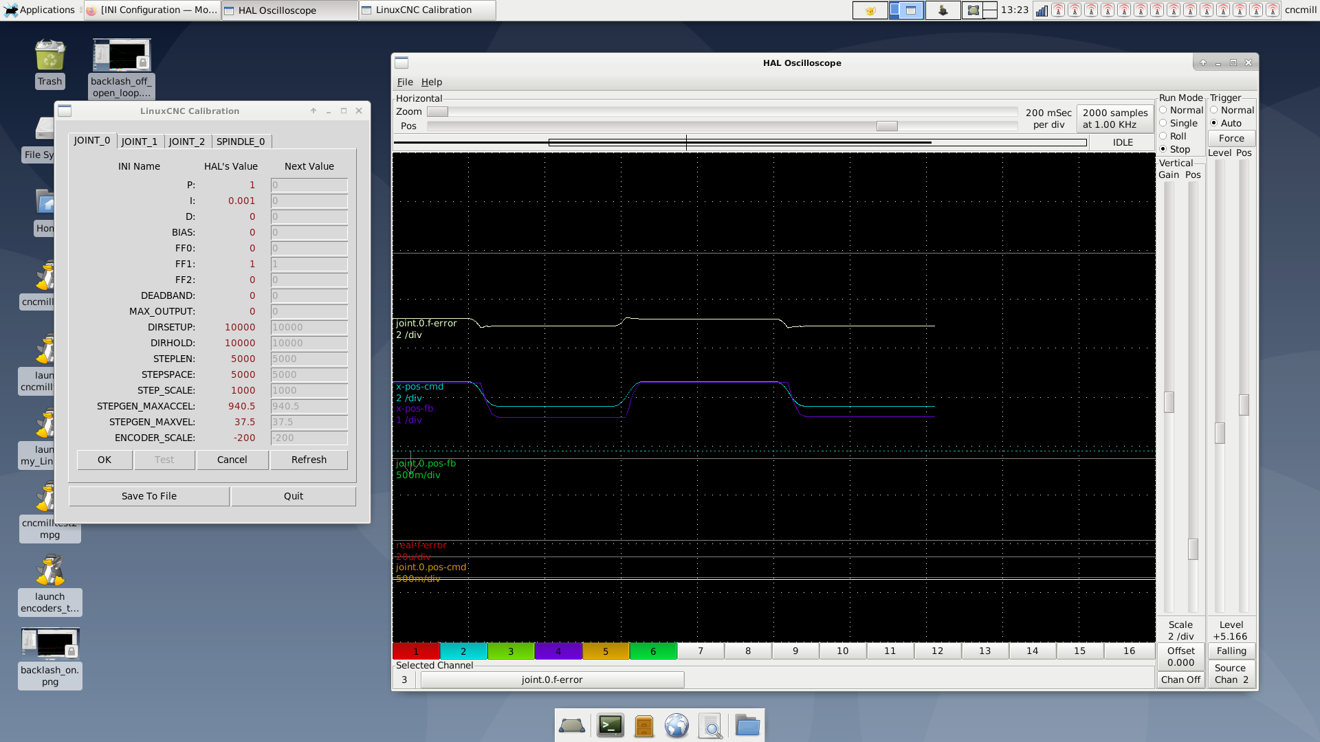
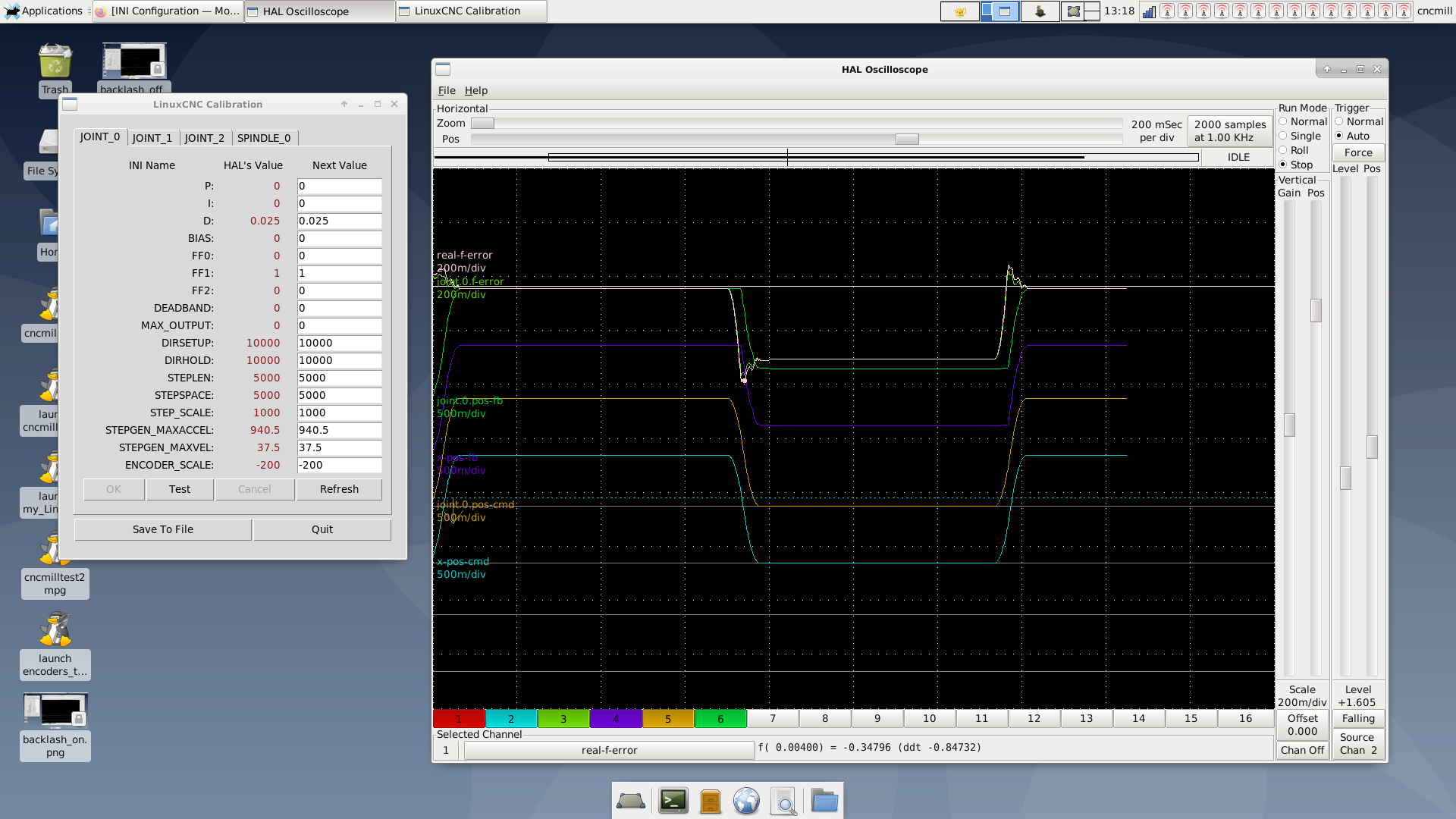
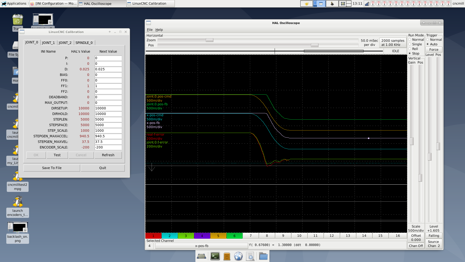
So once they are connected, if I put anything else than 0 for FF0, P or I, the axis starting running away. I doubled check that the encoder scale is in the right "orientation", it is.
FF1 at 1 and some small amount of D seems to help fight backlash and doesn't run away, but the axis becomes too stiff very fast and vibrates on long moves.
I really don't quite get what's going on with it.
any idea?
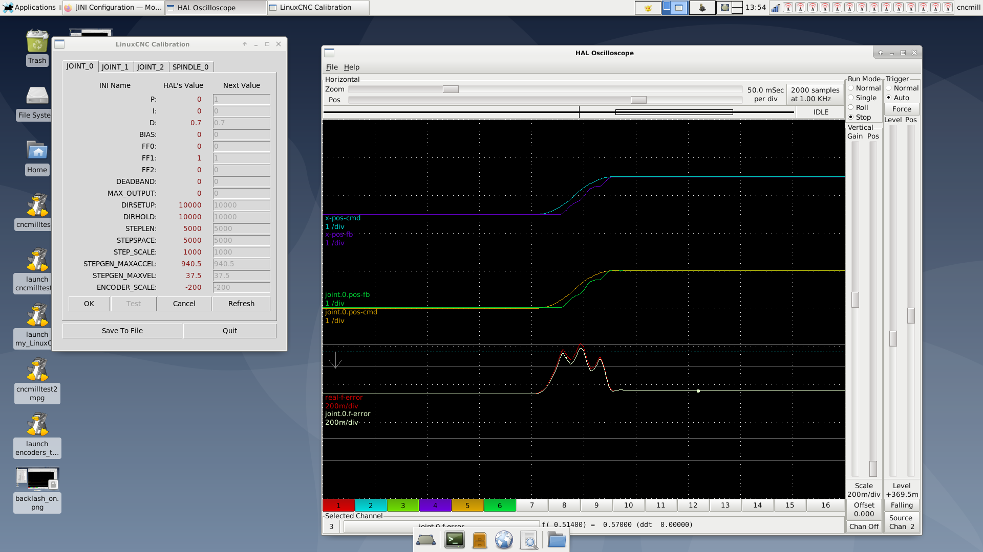
adding some scope captures with respective settings in calibration.
Basically once I connect the scale to the feedback, which I do this way, let me know if wrong:
net x-index-enable  <=> pid.x.index-enable
net x-enable        =>  pid.x.enable
net x-pos-cmd       =>  pid.x.command
net x-pos-fb        =>  pid.x.feedback
net x-output        <=  pid.x.output

setp    hm2_7i95.0.encoder.00.counter-mode 0
setp    hm2_7i95.0.encoder.00.filter 1
setp    hm2_7i95.0.encoder.00.index-invert 1
setp    hm2_7i95.0.encoder.00.index-mask 0
setp    hm2_7i95.0.encoder.00.index-mask-invert 0
setp    hm2_7i95.0.encoder.00.scale  [JOINT_0]ENCODER_SCALE

net x-pos-cmd    <= joint.0.motor-pos-cmd
net x-vel-cmd    <= joint.0.vel-cmd
net x-output     => hm2_7i95.0.stepgen.00.velocity-cmd
net x-pos-fb     => joint.0.motor-pos-fb
net x-enable     <= joint.0.amp-enable-out
net x-enable     => hm2_7i95.0.stepgen.00.enable

net x-pos-fb               <=  hm2_7i95.0.encoder.00.position
net x-vel-fb               <=  hm2_7i95.0.encoder.00.velocity
net x-pos-fb               =>  joint.0.motor-pos-fb
net x-index-enable    joint.0.index-enable  <=>  hm2_7i95.0.encoder.00.index-enable
net x-pos-rawcounts        <=  hm2_7i95.0.encoder.00.rawcounts
So once they are connected, if I put anything else than 0 for FF0, P or I, the axis starting running away. I doubled check that the encoder scale is in the right "orientation", it is.
FF1 at 1 and some small amount of D seems to help fight backlash and doesn't run away, but the axis becomes too stiff very fast and vibrates on long moves.
I really don't quite get what's going on with it.
any idea?
adding some scope captures with respective settings in calibration.
Attachments:
Last edit: 05 Oct 2022 12:10 by chienMouille.
Please Log in or Create an account to join the conversation.
- Todd Zuercher
-

- Offline
- Platinum Member
-
Less
More
- Posts: 4753
- Thank you received: 1458
05 Oct 2022 12:23 #253522
by Todd Zuercher
Andy,
That isn't what I've found with my servo drives. I have a machine running with position mode step/dir servos and encoder feedback being ran with a Mesa 5i25/7i85S set up. It behaves and tunes exactly like an ordinary velocity mode command servo set up. Because Linuxcnc still sees it as such because the Mesa stepgen is commanded with velocity commands and the PID is still working with velocity commands. The only difference with this persons install is that he is using a linear scale for position feedback to Linuxcnc and I'm using the motor's rotary encoder. The only difference that should cause will be potential instability and delays in responce at motor reversals due to backlash, but shouldn't change the basic tuning premise.
Replied by Todd Zuercher on topic linear scale and AC servo set up - sanity check
Is the servo being controlled in position mode or velocity mode?
If the step-dir is position then I would start with an FF0 of 1.0 and everything else zero. That should be identical to not having the scale feedback at all.
Then slowly increase the I gain (not the P) to pull out the accumulated error.
With a position to position loop I would expect a very small amoiunt of P to act like D on a position-velocity loop, and I to act like P.
Andy,
That isn't what I've found with my servo drives. I have a machine running with position mode step/dir servos and encoder feedback being ran with a Mesa 5i25/7i85S set up. It behaves and tunes exactly like an ordinary velocity mode command servo set up. Because Linuxcnc still sees it as such because the Mesa stepgen is commanded with velocity commands and the PID is still working with velocity commands. The only difference with this persons install is that he is using a linear scale for position feedback to Linuxcnc and I'm using the motor's rotary encoder. The only difference that should cause will be potential instability and delays in responce at motor reversals due to backlash, but shouldn't change the basic tuning premise.
Please Log in or Create an account to join the conversation.
- Todd Zuercher
-
- Offline
- Platinum Member
-
Less
More
- Posts: 4753
- Thank you received: 1458
05 Oct 2022 12:39 - 05 Oct 2022 12:39 #253523
by Todd Zuercher
Replied by Todd Zuercher on topic linear scale and AC servo set up - sanity check
I think you are on the right track with FF1=1, (that is what my setup uses.) Some small amount of D to help tame the oscillation at reversals due to backlash,
Use as much P as stability will allow, Also a little FF2 might help with the delay cause by the backlash.
So did adjusting the drive's tuning fix the big oscillations you were seeing with the open loop position commands like in the first Halscope traces you posted? I suspect that was the main source of your problems before. These last traces do look a lot better. Try following the steps for an ordinary velocity loop tuning tutorial. I think you should have better luck this time. But the delays from the backlash will still limit your systems potential. In other words you won't be able to tune it as stiff as you could if the backlash wasn't an issue.
Last edit: 05 Oct 2022 12:39 by Todd Zuercher.
Please Log in or Create an account to join the conversation.
- Todd Zuercher
-
- Offline
- Platinum Member
-
Less
More
- Posts: 4753
- Thank you received: 1458
05 Oct 2022 12:47 #253524
by Todd Zuercher
Replied by Todd Zuercher on topic linear scale and AC servo set up - sanity check
PS You shouldn't have needed to decrease your step pulse resolution to increase your speed and acceleration performance. The Mesa hardware is more than capable of generating MHz rate speed pulses. Personally I would choose to set the step pulse resolution equal to the resolution of either your motor encoder's resolution or your linearscale's resolution (with my personal preference being the motor's encoder resolution.) That is unless you were running into step timing and pulse width limitations with the drive reading the pulses.
Please Log in or Create an account to join the conversation.
- chienMouille
- Offline
- Senior Member
-
Less
More
- Posts: 73
- Thank you received: 3
05 Oct 2022 13:02 #253525
by chienMouille
Replied by chienMouille on topic linear scale and AC servo set up - sanity check
RE: step pulse resolution, I think I changed it cause LinuxCnC was warning me that my maxspeed was too high, when the actual speed of movement was under 1000mm/m. So I thought LinuxCNC couldn't deal with pulsing the drive fast enough. The drive never errored out, 10000 pulses is its default setting (same as the motor encoder)
Please Log in or Create an account to join the conversation.
Time to create page: 0.474 seconds