linear scale and AC servo set up - sanity check
- chienMouille
- Offline
- Senior Member
-

Less
More
- Posts: 73
- Thank you received: 3
05 Oct 2022 18:52 #253557
by chienMouille
Replied by chienMouille on topic linear scale and AC servo set up - sanity check
also why do some people use the pid.N.command-deriv pin?
should I connect this one?
should I connect this one?
Please Log in or Create an account to join the conversation.
- Todd Zuercher
-

- Offline
- Platinum Member
-

Less
More
- Posts: 4753
- Thank you received: 1458
06 Oct 2022 20:55 #253632
by Todd Zuercher
Replied by Todd Zuercher on topic linear scale and AC servo set up - sanity check
That pin you might want to connect the velocity feedback from the encoder (or what ever feedback devise.) If nothing is connected the value is calculated internally from the position feedback. There have been some historical bugs associated with this pin in the PID code. I am not sure if it is currently effective or beneficial to us it (it might be broken and has been in the past).
Please Log in or Create an account to join the conversation.
- Todd Zuercher
-
- Offline
- Platinum Member
-
Less
More
- Posts: 4753
- Thank you received: 1458
06 Oct 2022 21:18 #253637
by Todd Zuercher
That is called dithering, and is a normal servo condition. You may be able to stop it by setting a small deadband amount. Usually 1-2 encoder counts is enough to quiet it. So If your encoder scale is 200 set the deadband for maybe 0.0075.
Replied by Todd Zuercher on topic linear scale and AC servo set up - sanity check
ps: also now the axis goes back and forth between the two closest bits of the scale at rest (no command)
That is called dithering, and is a normal servo condition. You may be able to stop it by setting a small deadband amount. Usually 1-2 encoder counts is enough to quiet it. So If your encoder scale is 200 set the deadband for maybe 0.0075.
Please Log in or Create an account to join the conversation.
- andypugh
-

- Offline
- Moderator
-

Less
More
- Posts: 19871
- Thank you received: 4640
07 Oct 2022 10:31 #253667
by andypugh
Replied by andypugh on topic linear scale and AC servo set up - sanity check
I was rather assuming position-mode stepgen. It looks like you are actually running velocity-mode.
So once they are connected, if I put anything else than 0 for FF0, P or I, the axis starting running away. I doubled check that the encoder scale is in the right "orientation", it is.
Please Log in or Create an account to join the conversation.
- chienMouille
- Offline
- Senior Member
-
Less
More
- Posts: 73
- Thank you received: 3
07 Oct 2022 11:23 #253670
by chienMouille
Replied by chienMouille on topic linear scale and AC servo set up - sanity check
Im running in step/dir from a 7i95 mesa card, with the servo driver set in position mode.
Please Log in or Create an account to join the conversation.
- andypugh
-
- Offline
- Moderator
-
Less
More
- Posts: 19871
- Thank you received: 4640
07 Oct 2022 11:35 #253671
by andypugh
Yes, but you have the stepgen running in vocity mode, so the PID needs to output a velocity.
Now, what you could do (and it would be an interesting experiment) would be to run the normal Mesa-style velocity PID to close the stepgen position loop, and then add an outer loop like I described with the linear scale as feedback.
Parport setup:
Common Mesa config, using external velocity PID:
Alternative with scales:
Replied by andypugh on topic linear scale and AC servo set up - sanity check
Im running in step/dir from a 7i95 mesa card, with the servo driver set in position mode.
Yes, but you have the stepgen running in vocity mode, so the PID needs to output a velocity.
Now, what you could do (and it would be an interesting experiment) would be to run the normal Mesa-style velocity PID to close the stepgen position loop, and then add an outer loop like I described with the linear scale as feedback.
Parport setup:
joint.N.motor-pos.cmd -> stepgen.N.position-cmd
stepgen.N.pos-fb -> joint.N.motor-pos-fb
Common Mesa config, using external velocity PID:
joint.N.motor-pos.cmd -> pid.N.command
pid.N.output - > stepgen.N.velocity-cmd
stepgen.N.position-fb -> pid.N.feedback -> joint.N.pos-fb
Alternative with scales:
joint.N.motor-pos-cmd -> pid.M.command
pid.M.output -> pid.N.command
  pid.N.output - > stepgen.N.velocity-cmd
  stepgen.N.position-fb -> pid.N.feedback
scale.M.position -> pid.M.feedback -> joint.N.motor-pos-fb
Please Log in or Create an account to join the conversation.
- chienMouille
- Offline
- Senior Member
-
Less
More
- Posts: 73
- Thank you received: 3
07 Oct 2022 11:49 #253672
by chienMouille
Replied by chienMouille on topic linear scale and AC servo set up - sanity check
So it does seem that with command-deriv pin connected I get slightly better result (but maybe I'm imagining it, it's very minimal).
My current understanding is that what makes the PID hard to tune precisely is the difference between two situations: normal move forward and change of direction. The amount of movement required for the same command is pretty different, so would basically require different PID settings to be accurate and therefore trying to come up with a setting which would work for both requires the PID to be inaccurate (too wide ranging). Therefore the usual logic would be to try and close the gap between these two situations from a mechanical standpoint, aka removing the backlash.
I get this clearly now, and started CADing the machine to figure out how to replace the leadscrews for ball screws.
HOWEVER, for the sake of investigation and curiosity, here is something I wonder:
I get rather good results in open loop mode (without the scale feedback) and with Backlash Compensation on. (Mainly cause in exchange for a small position error I get much more responsiveness from the machine.) This, as I understand, is a blind software implementation: it watches for a change in direction and speeds through an added predefined distance blindly, before executing the actual move command. Of course backlash tending to be inconsistant between different parts of the screw, one would either need a lookup table with the screw modelled in, or contend with some drifting along the axis.
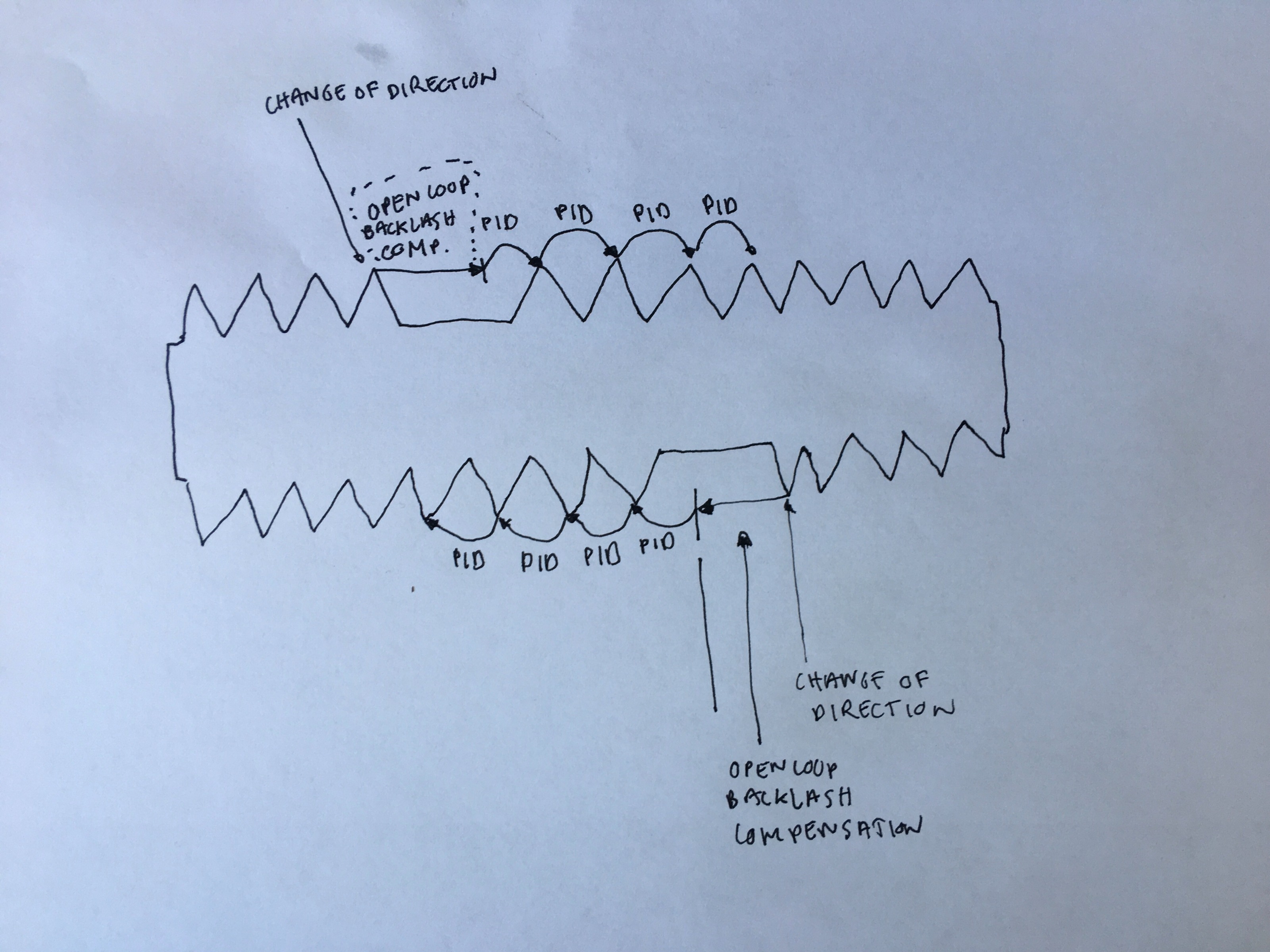
I might be delirious, but wouldn't pausing the PID on a direction change event for the time to speed forward the backlash distance and then switching back on to finalize the move work? It could have the advantage of keeping a singular situation for the PID to be tuned to. Basically keeping the closed loop for all forward movements, and opening the loop for the time of a forward jump at direction change. See illustration below.
I have tried to keep the backlash comp option on when set in closed loop, but it doesn't seem to do much, which I'm guessing is because of the constant PID calculations on top.
It doesn't theoretically seems difficult to implement in software as the event detection already exists (as shown by the open loop backlash compensation option).
Does it sound totally naive and stupid?
How would you go about writing a patch to test it? As a HAL component, or a LinuxCNC build?
My current understanding is that what makes the PID hard to tune precisely is the difference between two situations: normal move forward and change of direction. The amount of movement required for the same command is pretty different, so would basically require different PID settings to be accurate and therefore trying to come up with a setting which would work for both requires the PID to be inaccurate (too wide ranging). Therefore the usual logic would be to try and close the gap between these two situations from a mechanical standpoint, aka removing the backlash.
I get this clearly now, and started CADing the machine to figure out how to replace the leadscrews for ball screws.
HOWEVER, for the sake of investigation and curiosity, here is something I wonder:
I get rather good results in open loop mode (without the scale feedback) and with Backlash Compensation on. (Mainly cause in exchange for a small position error I get much more responsiveness from the machine.) This, as I understand, is a blind software implementation: it watches for a change in direction and speeds through an added predefined distance blindly, before executing the actual move command. Of course backlash tending to be inconsistant between different parts of the screw, one would either need a lookup table with the screw modelled in, or contend with some drifting along the axis.
I might be delirious, but wouldn't pausing the PID on a direction change event for the time to speed forward the backlash distance and then switching back on to finalize the move work? It could have the advantage of keeping a singular situation for the PID to be tuned to. Basically keeping the closed loop for all forward movements, and opening the loop for the time of a forward jump at direction change. See illustration below.
I have tried to keep the backlash comp option on when set in closed loop, but it doesn't seem to do much, which I'm guessing is because of the constant PID calculations on top.
It doesn't theoretically seems difficult to implement in software as the event detection already exists (as shown by the open loop backlash compensation option).
Does it sound totally naive and stupid?
How would you go about writing a patch to test it? As a HAL component, or a LinuxCNC build?
Attachments:
Please Log in or Create an account to join the conversation.
- andypugh
-
- Offline
- Moderator
-
Less
More
- Posts: 19871
- Thank you received: 4640
07 Oct 2022 11:55 #253675
by andypugh
Replied by andypugh on topic linear scale and AC servo set up - sanity check
I think that the idea I just posted (with FF0(M) = 1.0 and P(N) = 1000) would do that to an extent.
It is a standard (position mode) Mesa config with an additional correction loop.
It is a standard (position mode) Mesa config with an additional correction loop.
The following user(s) said Thank You: chienMouille
Please Log in or Create an account to join the conversation.
- chienMouille
- Offline
- Senior Member
-
Less
More
- Posts: 73
- Thank you received: 3
07 Oct 2022 11:56 #253676
by chienMouille
Replied by chienMouille on topic linear scale and AC servo set up - sanity check
Ok thanks Andy, I will try and implement this to test it.
[/code][/code][code][code]joint.N.motor-pos-cmd -> pid.M.command pid.M.output -> pid.N.command pid.N.output - > stepgen.N.velocity-cmd stepgen.N.position-fb -> pid.N.feedback scale.M.position -> pid.M.feedback -> joint.N.motor-pos-fb
Please Log in or Create an account to join the conversation.
- andypugh
-
- Offline
- Moderator
-
Less
More
- Posts: 19871
- Thank you received: 4640
07 Oct 2022 12:00 #253677
by andypugh
Replied by andypugh on topic linear scale and AC servo set up - sanity check
Start with the inner-loop exactly as pncconf set it up as a starting point.
Then check the system with PID.M.FF) = 1.0 and everything else in that PID set to zero, and it should be exactly the same as open-loop position mode.
Once you have confirmed that you can start adding some I (and maybe P) to the outer loop as a correction based on the scale.
Then check the system with PID.M.FF) = 1.0 and everything else in that PID set to zero, and it should be exactly the same as open-loop position mode.
Once you have confirmed that you can start adding some I (and maybe P) to the outer loop as a correction based on the scale.
Please Log in or Create an account to join the conversation.
Time to create page: 0.199 seconds