How to configure Horizontal Boring mill
- andypugh
-

- Offline
- Moderator
-

Less
More
- Posts: 19871
- Thank you received: 4640
15 Dec 2022 09:37 #259547
by andypugh
Replied by andypugh on topic How to configure Horizontal Boring mill
So it is probably hm2_5i24.0.pwm_frequency. But as I said, have a look at the pins of the running config to find out.
The following user(s) said Thank You: yrsiddhapura
Please Log in or Create an account to join the conversation.
- yrsiddhapura
- Offline
- Premium Member
-

Less
More
- Posts: 134
- Thank you received: 5
17 Dec 2022 17:13 - 17 Dec 2022 17:36 #259742
by yrsiddhapura
Replied by yrsiddhapura on topic How to configure Horizontal Boring mill
i tried to set
setp hm2_5i24.0.pwmgen.pwm_frequency 20000
to
setp hm2_5i24.0.pwmgen.pwm_frequency 3000 and even 2000 but its still same i am getting 60khz frequency and very minor changes in duty cycle as mine multi meter says(i dont have access to oscilloscope right now) i have checked PWM value and is 1100(mine required RPM) and Output rps is 18.36 (about 1100 RPM) but frequency cycle is above 60khz. And "halcmd show pin *pwm_frequency" shows nothing.
As following readhmid PIN 23 is PWMgen and as following 7i52s manual Pin 23 is TX5B and as following it i have connected PWM connection to P2 PIN No 21 of 7i52s and GND to P2 PIN No 17 of 7i52s for mine PWM to Voltage converter(Chines Generic module).does mine connections are wrong or i am missing any thing ?I am attaching mine HAL and INI files and readhmid output file.
setp hm2_5i24.0.pwmgen.pwm_frequency 20000
to
setp hm2_5i24.0.pwmgen.pwm_frequency 3000 and even 2000 but its still same i am getting 60khz frequency and very minor changes in duty cycle as mine multi meter says(i dont have access to oscilloscope right now) i have checked PWM value and is 1100(mine required RPM) and Output rps is 18.36 (about 1100 RPM) but frequency cycle is above 60khz. And "halcmd show pin *pwm_frequency" shows nothing.
HAL# Generated by PNCconf at Tue Dec 13 10:34:58 2022
# Using LinuxCNC version: 2.8
# If you make changes to this file, they will be
# overwritten when you run PNCconf again

loadrt [KINS]KINEMATICS
loadrt [EMCMOT]EMCMOT servo_period_nsec=[EMCMOT]SERVO_PERIOD num_joints=[KINS]JOINTS
loadrt hostmot2
loadrt hm2_pci config="firmware=hm2/Discovered:5i24/~/mesa0_discovered.xml.BIT num_encoders=12 num_pwmgens=1 num_stepgens=5 sserial_port_0=000100"
setp hm2_5i24.0.pwmgen.pwm_frequency 20000
setp hm2_5i24.0.pwmgen.pdm_frequency 6000000
setp hm2_5i24.0.watchdog.timeout_ns 5000000
setp hm2_5i24.0.gpio.000.is_output 1
setp hm2_5i24.0.gpio.023.is_output 1
loadrt pid names=pid.x,pid.y,pid.z,pid.w,pid.b,pid.s

addf hm2_5i24.0.read servo-thread
addf motion-command-handler servo-thread
addf motion-controller servo-thread
addf pid.x.do-pid-calcs servo-thread
addf pid.y.do-pid-calcs servo-thread
addf pid.z.do-pid-calcs servo-thread
addf pid.w.do-pid-calcs servo-thread
addf pid.b.do-pid-calcs servo-thread
addf pid.s.do-pid-calcs servo-thread
addf hm2_5i24.0.write servo-thread

# external output signals


# --- X-ENABLE ---
net x-enable => hm2_5i24.0.7i84.0.0.output-01

# --- Y-ENABLE ---
net y-enable => hm2_5i24.0.7i84.0.0.output-04

# --- Z-ENABLE ---
net z-enable => hm2_5i24.0.7i84.0.0.output-07

# --- W-ENABLE ---
net w-enable => hm2_5i24.0.7i84.0.0.output-10

# --- B-ENABLE ---
net b-enable => hm2_5i24.0.7i84.0.0.output-13

# --- COOLANT-FLOOD ---
net coolant-flood => hm2_5i24.0.7i84.0.1.output-06

# --- COOLANT-MIST ---
net coolant-mist => hm2_5i24.0.7i84.0.1.output-07

# --- SPINDLE-ENABLE ---
net spindle-enable => hm2_5i24.0.7i84.0.2.output-01

# --- SPINDLE-CW ---
net spindle-cw => hm2_5i24.0.7i84.0.2.output-03

# --- SPINDLE-CCW ---
net spindle-ccw => hm2_5i24.0.7i84.0.2.output-04

# external input signals


# --- MAX-X ---
net max-x <= hm2_5i24.0.7i84.0.1.input-01

# --- MIN-X ---
net min-x <= hm2_5i24.0.7i84.0.1.input-00

# --- HOME-X ---
net home-x <= hm2_5i24.0.7i84.0.1.input-02

# --- MAX-Y ---
net max-y <= hm2_5i24.0.7i84.0.1.input-03

# --- MIN-Y ---
net min-y <= hm2_5i24.0.7i84.0.1.input-04

# --- HOME-Y ---
net home-y <= hm2_5i24.0.7i84.0.1.input-05

# --- MAX-Z ---
net max-z <= hm2_5i24.0.7i84.0.1.input-06

# --- MIN-Z ---
net min-z <= hm2_5i24.0.7i84.0.1.input-07

# --- HOME-Z ---
net home-z <= hm2_5i24.0.7i84.0.1.input-08

# --- MAX-W ---
net max-W <= hm2_5i24.0.7i84.0.1.input-09

# --- MIN-W ---
net min-w <= hm2_5i24.0.7i84.0.1.input-10

# --- HOME-W ---
net home-w <= hm2_5i24.0.7i84.0.1.input-11


# --- MAX-B ---
#net max-b <= hm2_5i24.0.7i84.0.1.input-12

# --- MIN-B ---
#net min-b <= hm2_5i24.0.7i84.0.1.input-13

# --- HOME-B ---
net home-b <= hm2_5i24.0.7i84.0.1.input-15


# --- JOG-X-POS ---
net jog-x-pos <= hm2_5i24.0.7i84.0.2.input-09

# --- JOG-X-NEG ---
net jog-x-neg <= hm2_5i24.0.7i84.0.2.input-10

# --- JOG-Y-POS ---
net jog-y-pos <= hm2_5i24.0.7i84.0.2.input-11

# --- JOG-Y-NEG ---
net jog-y-neg <= hm2_5i24.0.7i84.0.2.input-12

# --- JOG-Z-POS ---
net jog-z-pos <= hm2_5i24.0.7i84.0.2.input-13

# --- JOG-Z-NEG ---
net jog-z-neg <= hm2_5i24.0.7i84.0.2.input-14

# --- ESTOP-EXT ---
net estop-ext <= hm2_5i24.0.7i84.0.2.input-20

#*******************
# AXIS X JOINT 0
#*******************

setp pid.x.Pgain [JOINT_0]P
setp pid.x.Igain [JOINT_0]I
setp pid.x.Dgain [JOINT_0]D
setp pid.x.bias [JOINT_0]BIAS
setp pid.x.FF0 [JOINT_0]FF0
setp pid.x.FF1 [JOINT_0]FF1
setp pid.x.FF2 [JOINT_0]FF2
setp pid.x.deadband [JOINT_0]DEADBAND
setp pid.x.maxoutput [JOINT_0]MAX_OUTPUT
setp pid.x.error-previous-target true
# This setting is to limit bogus stepgen
# velocity corrections caused by position
# feedback sample time jitter.
setp pid.x.maxerror 0.012700

net x-index-enable <=> pid.x.index-enable
net x-enable => pid.x.enable
net x-pos-cmd => pid.x.command
net x-pos-fb => pid.x.feedback
net x-output <= pid.x.output

# Step Gen signals/setup

setp hm2_5i24.0.stepgen.00.dirsetup [JOINT_0]DIRSETUP
setp hm2_5i24.0.stepgen.00.dirhold [JOINT_0]DIRHOLD
setp hm2_5i24.0.stepgen.00.steplen [JOINT_0]STEPLEN
setp hm2_5i24.0.stepgen.00.stepspace [JOINT_0]STEPSPACE
setp hm2_5i24.0.stepgen.00.position-scale [JOINT_0]STEP_SCALE
setp hm2_5i24.0.stepgen.00.step_type 0
setp hm2_5i24.0.stepgen.00.control-type 1
setp hm2_5i24.0.stepgen.00.maxaccel [JOINT_0]STEPGEN_MAXACCEL
setp hm2_5i24.0.stepgen.00.maxvel [JOINT_0]STEPGEN_MAXVEL

# ---closedloop stepper signals---

net x-pos-cmd <= joint.0.motor-pos-cmd
net x-vel-cmd <= joint.0.vel-cmd
net x-output <= hm2_5i24.0.stepgen.00.velocity-cmd
net x-pos-fb <= hm2_5i24.0.stepgen.00.position-fb
net x-pos-fb => joint.0.motor-pos-fb
net x-enable <= joint.0.amp-enable-out
net x-enable => hm2_5i24.0.stepgen.00.enable

# ---setup home / limit switch signals---

net home-x => joint.0.home-sw-in
net min-x => joint.0.neg-lim-sw-in
net max-x => joint.0.pos-lim-sw-in

#*******************
# AXIS Y JOINT 1
#*******************

setp pid.y.Pgain [JOINT_1]P
setp pid.y.Igain [JOINT_1]I
setp pid.y.Dgain [JOINT_1]D
setp pid.y.bias [JOINT_1]BIAS
setp pid.y.FF0 [JOINT_1]FF0
setp pid.y.FF1 [JOINT_1]FF1
setp pid.y.FF2 [JOINT_1]FF2
setp pid.y.deadband [JOINT_1]DEADBAND
setp pid.y.maxoutput [JOINT_1]MAX_OUTPUT
setp pid.y.error-previous-target true
# This setting is to limit bogus stepgen
# velocity corrections caused by position
# feedback sample time jitter.
setp pid.y.maxerror 0.012700

net y-index-enable <=> pid.y.index-enable
net y-enable => pid.y.enable
net y-pos-cmd => pid.y.command
net y-pos-fb => pid.y.feedback
net y-output <= pid.y.output

# Step Gen signals/setup

setp hm2_5i24.0.stepgen.01.dirsetup [JOINT_1]DIRSETUP
setp hm2_5i24.0.stepgen.01.dirhold [JOINT_1]DIRHOLD
setp hm2_5i24.0.stepgen.01.steplen [JOINT_1]STEPLEN
setp hm2_5i24.0.stepgen.01.stepspace [JOINT_1]STEPSPACE
setp hm2_5i24.0.stepgen.01.position-scale [JOINT_1]STEP_SCALE
setp hm2_5i24.0.stepgen.01.step_type 0
setp hm2_5i24.0.stepgen.01.control-type 1
setp hm2_5i24.0.stepgen.01.maxaccel [JOINT_1]STEPGEN_MAXACCEL
setp hm2_5i24.0.stepgen.01.maxvel [JOINT_1]STEPGEN_MAXVEL

# ---closedloop stepper signals---

net y-pos-cmd <= joint.1.motor-pos-cmd
net y-vel-cmd <= joint.1.vel-cmd
net y-output <= hm2_5i24.0.stepgen.01.velocity-cmd
net y-pos-fb <= hm2_5i24.0.stepgen.01.position-fb
net y-pos-fb => joint.1.motor-pos-fb
net y-enable <= joint.1.amp-enable-out
net y-enable => hm2_5i24.0.stepgen.01.enable

# ---setup home / limit switch signals---

net home-y => joint.1.home-sw-in
net min-y => joint.1.neg-lim-sw-in
net max-y => joint.1.pos-lim-sw-in

#*******************
# AXIS Z JOINT 2
#*******************

setp pid.z.Pgain [JOINT_2]P
setp pid.z.Igain [JOINT_2]I
setp pid.z.Dgain [JOINT_2]D
setp pid.z.bias [JOINT_2]BIAS
setp pid.z.FF0 [JOINT_2]FF0
setp pid.z.FF1 [JOINT_2]FF1
setp pid.z.FF2 [JOINT_2]FF2
setp pid.z.deadband [JOINT_2]DEADBAND
setp pid.z.maxoutput [JOINT_2]MAX_OUTPUT
setp pid.z.error-previous-target true
# This setting is to limit bogus stepgen
# velocity corrections caused by position
# feedback sample time jitter.
setp pid.z.maxerror 0.012700

net z-index-enable <=> pid.z.index-enable
net z-enable => pid.z.enable
net z-pos-cmd => pid.z.command
net z-pos-fb => pid.z.feedback
net z-output <= pid.z.output

# Step Gen signals/setup

setp hm2_5i24.0.stepgen.02.dirsetup [JOINT_2]DIRSETUP
setp hm2_5i24.0.stepgen.02.dirhold [JOINT_2]DIRHOLD
setp hm2_5i24.0.stepgen.02.steplen [JOINT_2]STEPLEN
setp hm2_5i24.0.stepgen.02.stepspace [JOINT_2]STEPSPACE
setp hm2_5i24.0.stepgen.02.position-scale [JOINT_2]STEP_SCALE
setp hm2_5i24.0.stepgen.02.step_type 0
setp hm2_5i24.0.stepgen.02.control-type 1
setp hm2_5i24.0.stepgen.02.maxaccel [JOINT_2]STEPGEN_MAXACCEL
setp hm2_5i24.0.stepgen.02.maxvel [JOINT_2]STEPGEN_MAXVEL

# ---closedloop stepper signals---

net z-pos-cmd <= joint.2.motor-pos-cmd
net z-vel-cmd <= joint.2.vel-cmd
net z-output <= hm2_5i24.0.stepgen.02.velocity-cmd
net z-pos-fb <= hm2_5i24.0.stepgen.02.position-fb
net z-pos-fb => joint.2.motor-pos-fb
net z-enable <= joint.2.amp-enable-out
net z-enable => hm2_5i24.0.stepgen.02.enable

# ---setup home / limit switch signals---

net home-z => joint.2.home-sw-in
net min-z => joint.2.neg-lim-sw-in
net max-z => joint.2.pos-lim-sw-in

#*******************
# AXIS W JOINT 3
#*******************

setp pid.w.Pgain [JOINT_3]P
setp pid.w.Igain [JOINT_3]I
setp pid.w.Dgain [JOINT_3]D
setp pid.w.bias [JOINT_3]BIAS
setp pid.w.FF0 [JOINT_3]FF0
setp pid.w.FF1 [JOINT_3]FF1
setp pid.w.FF2 [JOINT_3]FF2
setp pid.w.deadband [JOINT_3]DEADBAND
setp pid.w.maxoutput [JOINT_3]MAX_OUTPUT
setp pid.w.error-previous-target true
# This setting is to limit bogus stepgen
# velocity corrections caused by position
# feedback sample time jitter.
setp pid.w.maxerror 0.012700

net w-index-enable <=> pid.w.index-enable
net w-enable => pid.w.enable
net w-pos-cmd => pid.w.command
net w-pos-fb => pid.w.feedback
net w-output <= pid.w.output

# Step Gen signals/setup

setp hm2_5i24.0.stepgen.03.dirsetup [JOINT_3]DIRSETUP
setp hm2_5i24.0.stepgen.03.dirhold [JOINT_3]DIRHOLD
setp hm2_5i24.0.stepgen.03.steplen [JOINT_3]STEPLEN
setp hm2_5i24.0.stepgen.03.stepspace [JOINT_3]STEPSPACE
setp hm2_5i24.0.stepgen.03.position-scale [JOINT_3]STEP_SCALE
setp hm2_5i24.0.stepgen.03.step_type 0
setp hm2_5i24.0.stepgen.03.control-type 1
setp hm2_5i24.0.stepgen.03.maxaccel [JOINT_3]STEPGEN_MAXACCEL
setp hm2_5i24.0.stepgen.03.maxvel [JOINT_3]STEPGEN_MAXVEL

# ---closedloop stepper signals---

net w-pos-cmd <= joint.3.motor-pos-cmd
net w-vel-cmd <= joint.3.vel-cmd
net w-output <= hm2_5i24.0.stepgen.03.velocity-cmd
net w-pos-fb <= hm2_5i24.0.stepgen.03.position-fb
net w-pos-fb => joint.3.motor-pos-fb
net w-enable <= joint.3.amp-enable-out
net w-enable => hm2_5i24.0.stepgen.03.enable

# ---setup home / limit switch signals---

net home-w => joint.3.home-sw-in
net min-w => joint.3.neg-lim-sw-in
net max-w => joint.3.pos-lim-sw-in

#*******************
# AXIS B JOINT 4
#*******************

setp pid.b.Pgain [JOINT_4]P
setp pid.b.Igain [JOINT_4]I
setp pid.b.Dgain [JOINT_4]D
setp pid.b.bias [JOINT_4]BIAS
setp pid.b.FF0 [JOINT_4]FF0
setp pid.b.FF1 [JOINT_4]FF1
setp pid.b.FF2 [JOINT_4]FF2
setp pid.b.deadband [JOINT_4]DEADBAND
setp pid.b.maxoutput [JOINT_4]MAX_OUTPUT
setp pid.b.error-previous-target true
# This setting is to limit bogus stepgen
# velocity corrections caused by position
# feedback sample time jitter.
setp pid.b.maxerror 0.012700

net b-index-enable <=> pid.b.index-enable
net b-enable => pid.b.enable
net b-pos-cmd => pid.b.command
net b-pos-fb => pid.b.feedback
net b-output <= pid.b.output

# Step Gen signals/setup

setp hm2_5i24.0.stepgen.04.dirsetup [JOINT_4]DIRSETUP
setp hm2_5i24.0.stepgen.04.dirhold [JOINT_4]DIRHOLD
setp hm2_5i24.0.stepgen.04.steplen [JOINT_4]STEPLEN
setp hm2_5i24.0.stepgen.04.stepspace [JOINT_4]STEPSPACE
setp hm2_5i24.0.stepgen.04.position-scale [JOINT_4]STEP_SCALE
setp hm2_5i24.0.stepgen.04.step_type 0
setp hm2_5i24.0.stepgen.04.control-type 1
setp hm2_5i24.0.stepgen.04.maxaccel [JOINT_4]STEPGEN_MAXACCEL
setp hm2_5i24.0.stepgen.04.maxvel [JOINT_4]STEPGEN_MAXVEL

# ---closedloop stepper signals---

net b-pos-cmd <= joint.4.motor-pos-cmd
net b-vel-cmd <= joint.4.vel-cmd
net b-output <= hm2_5i24.0.stepgen.04.velocity-cmd
net b-pos-fb <= hm2_5i24.0.stepgen.04.position-fb
net b-pos-fb => joint.4.motor-pos-fb
net b-enable <= joint.4.amp-enable-out
net b-enable => hm2_5i24.0.stepgen.04.enable

# ---setup home / limit switch signals---
net home-b => joint.4.home-sw-in
#net min-b => joint.4.neg-lim-sw-in
#net max-b => joint.4.pos-lim-sw-in

#net b-home-sw => joint.4.home-sw-in
net b-neg-limit => joint.4.neg-lim-sw-in
net b-pos-limit => joint.4.pos-lim-sw-in


#*******************
# SPINDLE
#*******************

setp pid.s.Pgain [SPINDLE_0]P
setp pid.s.Igain [SPINDLE_0]I
setp pid.s.Dgain [SPINDLE_0]D
setp pid.s.bias [SPINDLE_0]BIAS
setp pid.s.FF0 [SPINDLE_0]FF0
setp pid.s.FF1 [SPINDLE_0]FF1
setp pid.s.FF2 [SPINDLE_0]FF2
setp pid.s.deadband [SPINDLE_0]DEADBAND
setp pid.s.maxoutput [SPINDLE_0]MAX_OUTPUT
setp pid.s.error-previous-target true

net spindle-index-enable <=> pid.s.index-enable
net spindle-enable => pid.s.enable
net spindle-vel-cmd-rpm => pid.s.command
net spindle-vel-fb-rpm => pid.s.feedback
net spindle-output <= pid.s.output

# ---PWM Generator signals/setup---

setp hm2_5i24.0.pwmgen.00.output-type 1
setp hm2_5i24.0.pwmgen.00.scale [SPINDLE_0]OUTPUT_SCALE


net spindle-vel-cmd-rpm => hm2_5i24.0.pwmgen.00.value
net spindle-enable => hm2_5i24.0.pwmgen.00.enable

# ---setup spindle control signals---

net spindle-vel-cmd-rps <= spindle.0.speed-out-rps
net spindle-vel-cmd-rps-abs <= spindle.0.speed-out-rps-abs
net spindle-vel-cmd-rpm <= spindle.0.speed-out
net spindle-vel-cmd-rpm-abs <= spindle.0.speed-out-abs
net spindle-enable <= spindle.0.on
net spindle-cw <= spindle.0.forward
net spindle-ccw <= spindle.0.reverse
net spindle-brake <= spindle.0.brake
net spindle-revs => spindle.0.revs
net spindle-at-speed => spindle.0.at-speed
net spindle-vel-fb-rps => spindle.0.speed-in
net spindle-index-enable <=> spindle.0.index-enable

# ---Setup spindle at speed signals---

sets spindle-at-speed true


#******************************
# connect miscellaneous signals
#******************************

# ---HALUI signals---

net axis-select-x halui.axis.x.select
net jog-x-pos halui.axis.x.plus
net jog-x-neg halui.axis.x.minus
net jog-x-analog halui.axis.x.analog
net x-is-homed halui.joint.0.is-homed
net axis-select-y halui.axis.y.select
net jog-y-pos halui.axis.y.plus
net jog-y-neg halui.axis.y.minus
net jog-y-analog halui.axis.y.analog
net y-is-homed halui.joint.1.is-homed
net axis-select-z halui.axis.z.select
net jog-z-pos halui.axis.z.plus
net jog-z-neg halui.axis.z.minus
net jog-z-analog halui.axis.z.analog
net z-is-homed halui.joint.2.is-homed
net axis-select-w halui.axis.w.select
net jog-w-pos halui.axis.w.plus
net jog-w-neg halui.axis.w.minus
net jog-w-analog halui.axis.w.analog
net w-is-homed halui.joint.3.is-homed
net jog-selected-pos halui.axis.selected.plus
net jog-selected-neg halui.axis.selected.minus
net spindle-manual-cw halui.spindle.0.forward
net spindle-manual-ccw halui.spindle.0.reverse
net spindle-manual-stop halui.spindle.0.stop
net machine-is-on halui.machine.is-on
net jog-speed halui.axis.jog-speed
net MDI-mode halui.mode.is-mdi

# ---coolant signals---

net coolant-mist <= iocontrol.0.coolant-mist
net coolant-flood <= iocontrol.0.coolant-flood

# ---probe signal---

net probe-in => motion.probe-input

# ---motion control signals---

net in-position <= motion.in-position
net machine-is-enabled <= motion.motion-enabled

# ---digital in / out signals---

# ---estop signals---

net estop-out <= iocontrol.0.user-enable-out
net estop-ext => iocontrol.0.emc-enable-in

# ---manual tool change signals---

loadusr -W hal_manualtoolchange
net tool-change-request iocontrol.0.tool-change => hal_manualtoolchange.change
net tool-change-confirmed iocontrol.0.tool-changed <= hal_manualtoolchange.changed
net tool-number iocontrol.0.tool-prep-number => hal_manualtoolchange.number
net tool-prepare-loopback iocontrol.0.tool-prepare => iocontrol.0.tool-prepared
INI# Generated by PNCconf at Tue Dec 13 10:34:58 2022
# Using LinuxCNC version: 2.8
# If you make changes to this file, they will be
# overwritten when you run PNCconf again
[EMC]
MACHINE = HBMMEC80
DEBUG = 0
VERSION = 1.1
[DISPLAY]
DISPLAY = axis
POSITION_OFFSET = RELATIVE
POSITION_FEEDBACK = ACTUAL
MAX_FEED_OVERRIDE = 2.000000
MAX_SPINDLE_OVERRIDE = 1.000000
MIN_SPINDLE_OVERRIDE = 0.500000
INTRO_GRAPHIC = linuxcnc.gif
INTRO_TIME = 5
PROGRAM_PREFIX = /home/lcnc/linuxcnc/nc_files
INCREMENTS = 5mm 1mm .5mm .1mm .05mm .01mm .005mm
POSITION_FEEDBACK = ACTUAL
DEFAULT_LINEAR_VELOCITY = 6.000000
MAX_LINEAR_VELOCITY = 100.000000
MIN_LINEAR_VELOCITY = 0.000167
DEFAULT_ANGULAR_VELOCITY = 3.000000
MAX_ANGULAR_VELOCITY = 12.000000
MIN_ANGULAR_VELOCITY = 0.006
EDITOR = gedit
GEOMETRY = bxyzw
[FILTER]
PROGRAM_EXTENSION = .png,.gif,.jpg Greyscale Depth Image
PROGRAM_EXTENSION = .py Python Script
png = image-to-gcode
gif = image-to-gcode
jpg = image-to-gcode
py = python
[TASK]
TASK = milltask
CYCLE_TIME = 0.010
[RS274NGC]
PARAMETER_FILE = linuxcnc.var
[EMCMOT]
EMCMOT = motmod
COMM_TIMEOUT = 1.0
SERVO_PERIOD = 1000000
[HMOT]
# **** This is for info only ****
CARD0=hm2_5i24.0
[HAL]
HALUI = halui
HALFILE = HBMMEC80.hal
HALFILE = custom.hal
POSTGUI_HALFILE = postgui_call_list.hal
SHUTDOWN = shutdown.hal
[HALUI]
[KINS]
JOINTS = 5
KINEMATICS = trivkins coordinates=XYZWB
[TRAJ]
COORDINATES = XYZWB
LINEAR_UNITS = mm
ANGULAR_UNITS = degree
DEFAULT_LINEAR_VELOCITY = 10.00
MAX_LINEAR_VELOCITY = 100.00
[EMCIO]
EMCIO = io
CYCLE_TIME = 0.100
TOOL_TABLE = tool.tbl
#******************************************
[AXIS_X]
MAX_VELOCITY = 100.0
MAX_ACCELERATION = 750.0
MIN_LIMIT = -0.01
MAX_LIMIT = 1200.0
[JOINT_0]
TYPE = LINEAR
HOME = 0.0
FERROR = 10.0
MIN_FERROR = 1.0
MAX_VELOCITY = 100.0
MAX_ACCELERATION = 750.0
# The values below should be 25% larger than MAX_VELOCITY and MAX_ACCELERATION
# If using BACKLASH compensation STEPGEN_MAXACCEL should be 100% larger.
STEPGEN_MAXVEL = 125.00
STEPGEN_MAXACCEL = 937.50
P = 1000.0
I = 0.0
D = 0.0
FF0 = 0.0
FF1 = 1.0
FF2 = 0.0
BIAS = 0.0
DEADBAND = 0.0
MAX_OUTPUT = 0.0
# these are in nanoseconds
DIRSETUP = 10000
DIRHOLD = 10000
STEPLEN = 2000
STEPSPACE = 2000
STEP_SCALE = 2000.0
MIN_LIMIT = -0.01
MAX_LIMIT = 1200.0
HOME_OFFSET = 0.000000
HOME_SEARCH_VEL = -1.000000
HOME_LATCH_VEL = -0.500000
HOME_FINAL_VEL = 0.000000
HOME_USE_INDEX = NO
HOME_SEQUENCE = 1
#******************************************
#******************************************
[AXIS_Y]
MAX_VELOCITY = 100.0
MAX_ACCELERATION = 750.0
MIN_LIMIT = -0.01
MAX_LIMIT = 1200.0
[JOINT_1]
TYPE = LINEAR
HOME = 0.0
FERROR = 10.0
MIN_FERROR = 1.0
MAX_VELOCITY = 100.0
MAX_ACCELERATION = 750.0
# The values below should be 25% larger than MAX_VELOCITY and MAX_ACCELERATION
# If using BACKLASH compensation STEPGEN_MAXACCEL should be 100% larger.
STEPGEN_MAXVEL = 125.00
STEPGEN_MAXACCEL = 937.50
P = 1000.0
I = 0.0
D = 0.0
FF0 = 0.0
FF1 = 1.0
FF2 = 0.0
BIAS = 0.0
DEADBAND = 0.0
MAX_OUTPUT = 0.0
# these are in nanoseconds
DIRSETUP = 10000
DIRHOLD = 10000
STEPLEN = 2000
STEPSPACE = 2000
STEP_SCALE = 2000.0
MIN_LIMIT = -0.01
MAX_LIMIT = 1200.0
HOME_OFFSET = 0.000000
HOME_SEARCH_VEL = -1.000000
HOME_LATCH_VEL = -0.500000
HOME_FINAL_VEL = 0.000000
HOME_USE_INDEX = NO
HOME_SEQUENCE = 2
#******************************************
#******************************************
[AXIS_Z]
MAX_VELOCITY = 100.0
MAX_ACCELERATION = 750.0
MIN_LIMIT = -1000.0
MAX_LIMIT = 0.01
[JOINT_2]
TYPE = LINEAR
HOME = 0.0
FERROR = 10.0
MIN_FERROR = 1.0
MAX_VELOCITY = 100.0
MAX_ACCELERATION = 750.0
# The values below should be 25% larger than MAX_VELOCITY and MAX_ACCELERATION
# If using BACKLASH compensation STEPGEN_MAXACCEL should be 100% larger.
STEPGEN_MAXVEL = 125.00
STEPGEN_MAXACCEL = 937.50
P = 1000.0
I = 0.0
D = 0.0
FF0 = 0.0
FF1 = 1.0
FF2 = 0.0
BIAS = 0.0
DEADBAND = 0.0
MAX_OUTPUT = 0.0
# these are in nanoseconds
DIRSETUP = 10000
DIRHOLD = 10000
STEPLEN = 2000
STEPSPACE = 2000
STEP_SCALE = 2000.0
MIN_LIMIT = -1000.0
MAX_LIMIT = 0.01
HOME_OFFSET = 0.000000
HOME_SEARCH_VEL = -1.000000
HOME_LATCH_VEL = -0.500000
HOME_FINAL_VEL = 0.000000
HOME_USE_INDEX = NO
HOME_SEQUENCE = 0
#******************************************
#******************************************
#******************************************
[AXIS_W]
MAX_VELOCITY = 100.0
MAX_ACCELERATION = 750.0
MIN_LIMIT = -0.01
MAX_LIMIT = 600.0
[JOINT_3]
TYPE = LINEAR
HOME = 0.0
FERROR = 10.0
MIN_FERROR = 1.0
MAX_VELOCITY = 100.0
MAX_ACCELERATION = 750.0
# The values below should be 25% larger than MAX_VELOCITY and MAX_ACCELERATION
# If using BACKLASH compensation STEPGEN_MAXACCEL should be 100% larger.
STEPGEN_MAXVEL = 125.00
STEPGEN_MAXACCEL = 937.50
P = 1000.0
I = 0.0
D = 0.0
FF0 = 0.0
FF1 = 1.0
FF2 = 0.0
BIAS = 0.0
DEADBAND = 0.0
MAX_OUTPUT = 0.0
# these are in nanoseconds
DIRSETUP = 10000
DIRHOLD = 10000
STEPLEN = 2000
STEPSPACE = 2000
STEP_SCALE = 2000.0
MIN_LIMIT = -0.01
MAX_LIMIT = 600.0
HOME_OFFSET = 0.000000
HOME_SEARCH_VEL = -1.000000
HOME_LATCH_VEL = -0.500000
HOME_FINAL_VEL = 0.000000
HOME_USE_INDEX = NO
HOME_SEQUENCE = 4
#******************************************
#******************************************
[AXIS_B]
MAX_VELOCITY = 12.0
MAX_ACCELERATION = 1200.0
MIN_LIMIT = -9999.0
MAX_LIMIT = 9999.0
[JOINT_4]
TYPE = ANGULAR
HOME = 0.0
FERROR = 0.5
MIN_FERROR = 0.05
MAX_VELOCITY = 12.0
MAX_ACCELERATION = 1200.0
# The values below should be 25% larger than MAX_VELOCITY and MAX_ACCELERATION
# If using BACKLASH compensation STEPGEN_MAXACCEL should be 100% larger.
STEPGEN_MAXVEL = 37.50
STEPGEN_MAXACCEL = 1500.00
P = 1000.0
I = 0.0
D = 0.0
FF0 = 0.0
FF1 = 1.0
FF2 = 0.0
BIAS = 0.0
DEADBAND = 0.0
MAX_OUTPUT = 0.0
# these are in nanoseconds
DIRSETUP = 10000
DIRHOLD = 10000
STEPLEN = 1500
STEPSPACE = 1500
STEP_SCALE = -7200
MIN_LIMIT = -9999.0
MAX_LIMIT = 9999.0
HOME_OFFSET = 0.000000
HOME_SEARCH_VEL = -2.000000
HOME_LATCH_VEL = -0.500000
HOME_FINAL_VEL = 0.000000
HOME_USE_INDEX = NO
#HOME_OFFSET = 0.0
#******************************************
[SPINDLE_0]
P = 0.0
I = 0.0
D = 0.0
FF0 = 1.0
FF1 = 0.0
FF2 = 0.0
BIAS = 0.0
DEADBAND = 0.0
MAX_OUTPUT = 1100.0
OUTPUT_SCALE = 1100
OUTPUT_MIN_LIMIT = 0
OUTPUT_MAX_LIMIT = 1100READHMID
General configuration information:
BoardName : MESA5I24
FPGA Size: 25 KGates
FPGA Pins: 256
Number of IO Ports: 3
Width of one I/O port: 24
Clock Low frequency: 33.3333 MHz
Clock High frequency: 200.0000 MHz
IDROM Type: 3
Instance Stride 0: 4
Instance Stride 1: 64
Register Stride 0: 256
Register Stride 1: 256
Modules in configuration:
Module: DPLL
There are 1 of DPLL in configuration
Version: 0
Registers: 7
BaseAddress: 7000
ClockFrequency: 33.333 MHz
Register Stride: 256 bytes
Instance Stride: 4 bytes
Module: WatchDog
There are 1 of WatchDog in configuration
Version: 0
Registers: 3
BaseAddress: 0C00
ClockFrequency: 33.333 MHz
Register Stride: 256 bytes
Instance Stride: 4 bytes
Module: IOPort
There are 3 of IOPort in configuration
Version: 0
Registers: 5
BaseAddress: 1000
ClockFrequency: 33.333 MHz
Register Stride: 256 bytes
Instance Stride: 4 bytes
Module: MuxedQCount
There are 12 of MuxedQCount in configuration
Version: 4
Registers: 5
BaseAddress: 3600
ClockFrequency: 33.333 MHz
Register Stride: 256 bytes
Instance Stride: 4 bytes
Module: MuxedQCountSel
There are 1 of MuxedQCountSel in configuration
Version: 0
Registers: 0
BaseAddress: 0000
ClockFrequency: 33.333 MHz
Register Stride: 256 bytes
Instance Stride: 4 bytes
Module: PWM
There are 1 of PWM in configuration
Version: 0
Registers: 5
BaseAddress: 4100
ClockFrequency: 200.000 MHz
Register Stride: 256 bytes
Instance Stride: 4 bytes
Module: SSerial
There are 1 of SSerial in configuration
Version: 0
Registers: 6
BaseAddress: 5B00
ClockFrequency: 33.333 MHz
Register Stride: 256 bytes
Instance Stride: 64 bytes
Module: StepGen
There are 5 of StepGen in configuration
Version: 2
Registers: 10
BaseAddress: 2000
ClockFrequency: 33.333 MHz
Register Stride: 256 bytes
Instance Stride: 4 bytes
Module: LED
There are 1 of LED in configuration
Version: 0
Registers: 1
BaseAddress: 0200
ClockFrequency: 33.333 MHz
Register Stride: 256 bytes
Instance Stride: 4 bytes
Configuration pin-out:
IO Connections for P4
Pin# I/O Pri. func Sec. func Chan Sec. Pin func Sec. Pin Dir
1 0 IOPort None
3 1 IOPort MuxedQCount 0 MuxQ-A (In)
5 2 IOPort MuxedQCount 0 MuxQ-B (In)
7 3 IOPort MuxedQCount 0 MuxQ-IDX (In)
9 4 IOPort MuxedQCount 1 MuxQ-A (In)
11 5 IOPort MuxedQCount 1 MuxQ-B (In)
13 6 IOPort MuxedQCount 1 MuxQ-IDX (In)
15 7 IOPort MuxedQCount 2 MuxQ-A (In)
17 8 IOPort MuxedQCount 2 MuxQ-B (In)
19 9 IOPort MuxedQCount 2 MuxQ-IDX (In)
21 10 IOPort MuxedQCountSel 0 MuxSel0 (Out)
23 11 IOPort PWM 0 PWM (Out)
25 12 IOPort None
27 13 IOPort StepGen 4 Step/Table1 (Out)
29 14 IOPort StepGen 4 Dir/Table2 (Out)
31 15 IOPort StepGen 3 Step/Table1 (Out)
33 16 IOPort StepGen 3 Dir/Table2 (Out)
35 17 IOPort StepGen 2 Step/Table1 (Out)
37 18 IOPort StepGen 2 Dir/Table2 (Out)
39 19 IOPort StepGen 1 Step/Table1 (Out)
41 20 IOPort StepGen 1 Dir/Table2 (Out)
43 21 IOPort StepGen 0 Step/Table1 (Out)
45 22 IOPort StepGen 0 Dir/Table2 (Out)
47 23 IOPort None
IO Connections for P3
Pin# I/O Pri. func Sec. func Chan Sec. Pin func Sec. Pin Dir
1 24 IOPort SSerial 0 TXEn3 (Out)
3 25 IOPort MuxedQCount 3 MuxQ-A (In)
5 26 IOPort MuxedQCount 3 MuxQ-B (In)
7 27 IOPort MuxedQCount 3 MuxQ-IDX (In)
9 28 IOPort MuxedQCount 4 MuxQ-A (In)
11 29 IOPort MuxedQCount 4 MuxQ-B (In)
13 30 IOPort MuxedQCount 4 MuxQ-IDX (In)
15 31 IOPort MuxedQCount 5 MuxQ-A (In)
17 32 IOPort MuxedQCount 5 MuxQ-B (In)
19 33 IOPort MuxedQCount 5 MuxQ-IDX (In)
21 34 IOPort MuxedQCountSel 6 MuxSel0 (Out)
23 35 IOPort SSerial 0 TXData5 (Out)
25 36 IOPort SSerial 0 RXData5 (In)
27 37 IOPort SSerial 0 TXData4 (Out)
29 38 IOPort SSerial 0 RXData4 (In)
31 39 IOPort SSerial 0 TXData3 (Out)
33 40 IOPort SSerial 0 RXData3 (In)
35 41 IOPort SSerial 0 TXData2 (Out)
37 42 IOPort SSerial 0 RXData2 (In)
39 43 IOPort SSerial 0 TXData1 (Out)
41 44 IOPort SSerial 0 RXData1 (In)
43 45 IOPort SSerial 0 TXData0 (Out)
45 46 IOPort SSerial 0 RXData0 (In)
47 47 IOPort SSerial 0 TXEn0 (Out)
IO Connections for P2
Pin# I/O Pri. func Sec. func Chan Sec. Pin func Sec. Pin Dir
1 48 IOPort None
3 49 IOPort None
5 50 IOPort None
7 51 IOPort None
9 52 IOPort None
11 53 IOPort None
13 54 IOPort None
15 55 IOPort None
17 56 IOPort None
19 57 IOPort None
21 58 IOPort None
23 59 IOPort None
25 60 IOPort None
27 61 IOPort None
29 62 IOPort None
31 63 IOPort None
33 64 IOPort None
35 65 IOPort None
37 66 IOPort None
39 67 IOPort None
41 68 IOPort None
43 69 IOPort None
45 70 IOPort None
47 71 IOPort NoneAs following readhmid PIN 23 is PWMgen and as following 7i52s manual Pin 23 is TX5B and as following it i have connected PWM connection to P2 PIN No 21 of 7i52s and GND to P2 PIN No 17 of 7i52s for mine PWM to Voltage converter(Chines Generic module).does mine connections are wrong or i am missing any thing ?I am attaching mine HAL and INI files and readhmid output file.
Last edit: 17 Dec 2022 17:36 by andypugh.
Please Log in or Create an account to join the conversation.
- andypugh
-
- Offline
- Moderator
-
Less
More
- Posts: 19871
- Thank you received: 4640
17 Dec 2022 17:41 #259747
by andypugh
Maybe it is using PDM mode? (though from this line in the HAL I would expect 6 MHz)
Add
linuxcnc.org/docs/stable/html/man/man9/hostmot2.9.html#pwmgen
Replied by andypugh on topic How to configure Horizontal Boring mill
setp hm2_5i24.0.pwmgen.pwm_frequency 3000 and even 2000 but its still same i am getting 60khz frequency
...setp hm2_5i24.0.pwmgen.pwm_frequency 20000 setp hm2_5i24.0.pwmgen.pdm_frequency 6000000
Maybe it is using PDM mode? (though from this line in the HAL I would expect 6 MHz)
Add
setp hm2_5i24.0.pwmgen.output-type 1linuxcnc.org/docs/stable/html/man/man9/hostmot2.9.html#pwmgen
The following user(s) said Thank You: yrsiddhapura
Please Log in or Create an account to join the conversation.
- yrsiddhapura
- Offline
- Premium Member
-
Less
More
- Posts: 134
- Thank you received: 5
17 Dec 2022 18:53 #259755
by yrsiddhapura
Replied by yrsiddhapura on topic How to configure Horizontal Boring mill
I think it's type-1 is pwm according to manual
output-type
This emulates the output_type load-time argument to the software pwmgen component. This parameter may be changed at runtime, but most of the time you probably want to set it at startup and then leave it alone. Accepted values are 1 (PWM on Out0 and Direction on Out1), 2 (Up on Out0 and Down on Out1), 3 (PDM mode, PDM on Out0 and Dir on Out1), and 4 (Direction on Out0 and PWM on Out1, "for locked antiphase").
As novice i am not sure which type is suitable for me could you pls suggest ?
Please Log in or Create an account to join the conversation.
- andypugh
-
- Offline
- Moderator
-
Less
More
- Posts: 19871
- Thank you received: 4640
17 Dec 2022 19:41 #259763
by andypugh
Replied by andypugh on topic How to configure Horizontal Boring mill
Yes, you want type 1.
Also try just deleting the PDM frequency line.
Also try just deleting the PDM frequency line.
The following user(s) said Thank You: yrsiddhapura
Please Log in or Create an account to join the conversation.
- yrsiddhapura
- Offline
- Premium Member
-
Less
More
- Posts: 134
- Thank you received: 5
18 Dec 2022 06:16 #259799
by yrsiddhapura
Replied by yrsiddhapura on topic How to configure Horizontal Boring mill
No changes after deleting pdm line still not able to get 2khz pwm afters settings pwm_frequancy to 2000 it's still got about. But according to mine volt meter it change voltages 0-5v so it is safe to use it as analogue my drive supports both 10v and 5v analogue input or i should connect/TX5B => pwm in and TX5B => GND , currently i have connected TX5B => pwm in and GND to GND of 7i52s
Please Log in or Create an account to join the conversation.
- andypugh
-
- Offline
- Moderator
-
Less
More
- Posts: 19871
- Thank you received: 4640
18 Dec 2022 10:09 #259810
by andypugh
Replied by andypugh on topic How to configure Horizontal Boring mill
The multimeter is averaging the PWM. The drive _might_ accept the 60kHz, but really you should set the PWM frequency to what the manual says.
With LinuxCNC running, what is the value shown on the pwm_frequency pin? (Use halmeter or "show hal configuration" from the "machine" menu to check this.
How are you measuring the PWM frequency and duty cycle? Maybe the measurement is wrong?
With LinuxCNC running, what is the value shown on the pwm_frequency pin? (Use halmeter or "show hal configuration" from the "machine" menu to check this.
How are you measuring the PWM frequency and duty cycle? Maybe the measurement is wrong?
Please Log in or Create an account to join the conversation.
- yrsiddhapura
- Offline
- Premium Member
-
Less
More
- Posts: 134
- Thank you received: 5
18 Dec 2022 18:25 #259842
by yrsiddhapura
Replied by yrsiddhapura on topic How to configure Horizontal Boring mill
Hal meter shows value of pwm_value 1100 @ 18.35 rps(1100 rpm) spindle out and to measure pwm frequency and duty i am using mine kaiweets ht118a which supports 10mhz frequency and duty cycle. Well yes I am also believe measurements are wrong so try to get access to ocilloscope
Please Log in or Create an account to join the conversation.
- andypugh
-
- Offline
- Moderator
-
Less
More
- Posts: 19871
- Thank you received: 4640
19 Dec 2022 23:21 #259909
by andypugh
Replied by andypugh on topic How to configure Horizontal Boring mill
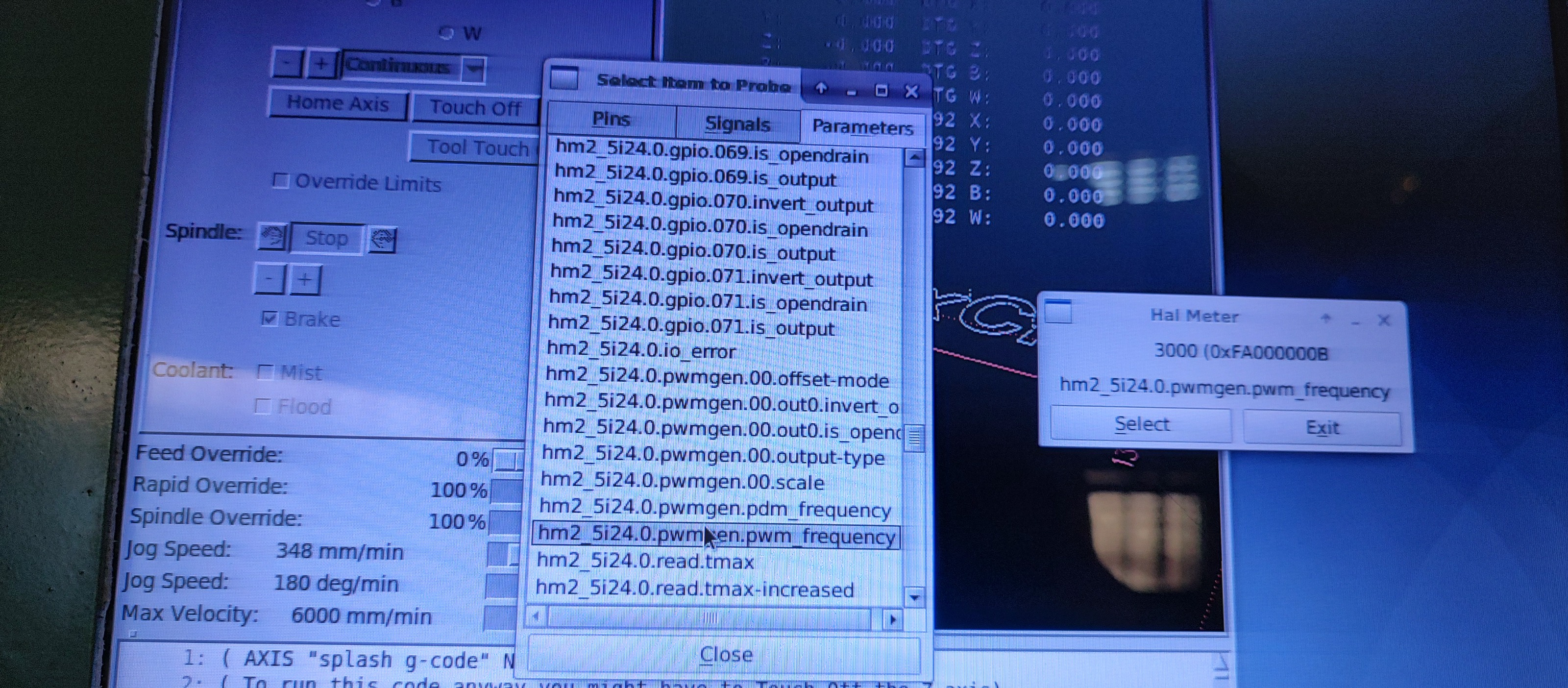
I asked about the pwm_frequency pin, to see if it really was being set to the right value (and not being set to another value elsewhere in the HAL files)
The following user(s) said Thank You: yrsiddhapura
Please Log in or Create an account to join the conversation.
- yrsiddhapura
- Offline
- Premium Member
-
Less
More
- Posts: 134
- Thank you received: 5
22 Dec 2022 11:23 #260072
by yrsiddhapura
Replied by yrsiddhapura on topic How to configure Horizontal Boring mill
pwm_frequency says 3000
Attachments:
Please Log in or Create an account to join the conversation.
Time to create page: 0.552 seconds