- Hardware & Machines
- CNC Machines
- Milling Machines
- Set up using AMC AB15A100 drives, brushed DC motor Prototrak Plus with Encoders
Set up using AMC AB15A100 drives, brushed DC motor Prototrak Plus with Encoders
- new2linux
- Offline
- Platinum Member
-

Less
More
- Posts: 711
- Thank you received: 9
12 Aug 2022 15:17 - 12 Aug 2022 16:08 #249596
by new2linux
Replied by new2linux on topic Set up using AMC AB15A100 drives, brushed DC motor Prototrak Plus with Encoders
Todd, thanks! I have 3 of the 4 probes calibrated, 1 of them is stuck or something, plastic screw will not turn. To be clear in my mind, your suggestion:
"The probe for channel#1 on the scope would be connected to pins #4 and #5 (along with the analog output of the 7i77.)"
For channel 1, as follows. This is P1(on A-M-C drive) pin 4 = +REF IN; pin 5 = -REF IN; in addition to the 7i77 card TB5 (the 4th (A OUT) & last spot). As per my diagram (page1, posted here: 06 Dec 2021 15:22 - 13 Jun 2022 18:25 #228440) pin 4 (on TB5 Drv) is going to pin 4 on P1 (the A-M-C drive) all ready. Am I to put scope between this, a temporary wire between the 2 points described?
Channel 2 is the probe connected at pin 8, (current monitor on P1, on A-M-C drive) & pin 2 (Signal GND) on same P1 (Signal Connector).
Many thanks!
Edit: Quick review; SW1 settings are: 1, 2, & 4 = OFF & 3 = ON. The factory default for 5 & 6 is ON. Pot 2 stays at 11.0 turns CW (as per equation in earlier post). Should Pot 1 & 3 & 4 be set to full CCW, this is factory settings?
Last edit: 12 Aug 2022 16:08 by new2linux. Reason: Review
Please Log in or Create an account to join the conversation.
- Todd Zuercher
-

- Offline
- Platinum Member
-
Less
More
- Posts: 4753
- Thank you received: 1458
12 Aug 2022 16:05 #249600
by Todd Zuercher
Replied by Todd Zuercher on topic Set up using AMC AB15A100 drives, brushed DC motor Prototrak Plus with Encoders
You may not need add a temporary wire to connect the probe, if there is already a wire there. All you need is enough space of exposed wire without insulation to clip the probe onto the existing wire. (Just be careful not to short anything out with the larger alligator clip for the ground, a bit of extra wire might be helpful for that.)
The following user(s) said Thank You: new2linux
Please Log in or Create an account to join the conversation.
- new2linux
- Offline
- Platinum Member
-
Less
More
- Posts: 711
- Thank you received: 9
12 Aug 2022 16:52 - 12 Aug 2022 18:10 #249603
by new2linux
Replied by new2linux on topic Set up using AMC AB15A100 drives, brushed DC motor Prototrak Plus with Encoders
Todd, Thanks! I understand channel 2, on AMC drive, pin 8 has the probe connected, alligator clip goes to pin 2 GND.
Now channel 1; pin 4 = +REF IN; and pin 5 = -REF IN in addition to analog output (A-OUT) of the 7i77. Do the pins 4 & 5 & A-OUT go to the probe, & the alligator goes to GND or the A-OUT? I am shore it is me, but I am not shore of the probe vs. the alligator clip and 3 places it need to connect or monitor.
Does Pot 1, 3 & 4, need to be to factory settings? Pot 2 is set to motor requirements and SW1-5 & 6 stay OFF. Looking at SW1, only one that is ON is 3, all the others are OFF.
Many thanks!
Edit: Todd, thanks for all of your help. It's late in the week as to hope to finish all the set-up. I will get my temp wires sorted over the weekend, it only looks to be a few, this way I can know with some confidence that all is correct. I will try the settings as per YouTube on scope, knowing that as per your suggestion that these may need tweaking. Next week, I will start the comparison of the traces to the App note 15, as to see what necessary dip switches are required, hopefully. I have not been able to open the LinuxCnc "test" as to generate test signal, but will over the weekend and see what develops, I am not seeing a way to start or run.
Many thanks!
Last edit: 12 Aug 2022 18:10 by new2linux.
Please Log in or Create an account to join the conversation.
- Todd Zuercher
-
- Offline
- Platinum Member
-
Less
More
- Posts: 4753
- Thank you received: 1458
12 Aug 2022 18:57 #249612
by Todd Zuercher
Replied by Todd Zuercher on topic Set up using AMC AB15A100 drives, brushed DC motor Prototrak Plus with Encoders
Yes, connect the channel#1 probe to pin4(+REF IN)/7i77(A-OUT), and the probe's ground to pin5(-REF IN)/7i77(GND).
I'm not sure that pot1 matters. (It is disabled when you switch the dip switches to current mode.)
Pot2 should be set for your motor's current limit.
Pot3 I have no idea. (factory default is probably as good of a setting as any.)
Pot 4 should be set for approximately zero offset. (Not sure it matters a whole lot.)
SW1-3 should be the only switch that you need to change to change from velocity to current mode for the current loop tuning. The rest of the SW1 switches should stay where they were.
The following user(s) said Thank You: new2linux
Please Log in or Create an account to join the conversation.
- new2linux
- Offline
- Platinum Member
-
Less
More
- Posts: 711
- Thank you received: 9
15 Aug 2022 12:16 #249774
by new2linux
Replied by new2linux on topic Set up using AMC AB15A100 drives, brushed DC motor Prototrak Plus with Encoders
Todd, thanks for all the help! Attached is a diagram as to how the scope is attached. Considering that the probes need to be calibrated & used only with the channel that the probe was calibrated with, the temporary wires that will be necessary should be as short as possible, so no error is introduced, is my thinking.
The "test .zip" after coping the files to the directory, I am not able to see a screen like the one at this post: 16 Jun 2022 14:37 - 16 Jun 2022 15:58 #245270. I am not shore how to open the file or maybe how to access it.
Many thanks!
The "test .zip" after coping the files to the directory, I am not able to see a screen like the one at this post: 16 Jun 2022 14:37 - 16 Jun 2022 15:58 #245270. I am not shore how to open the file or maybe how to access it.
Many thanks!
Please Log in or Create an account to join the conversation.
- Todd Zuercher
-
- Offline
- Platinum Member
-
Less
More
- Posts: 4753
- Thank you received: 1458
15 Aug 2022 12:45 #249776
by Todd Zuercher
Replied by Todd Zuercher on topic Set up using AMC AB15A100 drives, brushed DC motor Prototrak Plus with Encoders
The diagram looks fine.
Did you make the file "test.demo" executable?
There are two ways to open the file, the first is choose it from the Linuxcnc Config Picker, the 2nd is to type "~/linuxcnc/configs/test/test.demo" at the command prompt. (Assuming you have it saved to that dir.)
Did you make the file "test.demo" executable?
There are two ways to open the file, the first is choose it from the Linuxcnc Config Picker, the 2nd is to type "~/linuxcnc/configs/test/test.demo" at the command prompt. (Assuming you have it saved to that dir.)
The following user(s) said Thank You: new2linux
Please Log in or Create an account to join the conversation.
- Todd Zuercher
-
- Offline
- Platinum Member
-
Less
More
- Posts: 4753
- Thank you received: 1458
15 Aug 2022 12:50 #249778
by Todd Zuercher
Replied by Todd Zuercher on topic Set up using AMC AB15A100 drives, brushed DC motor Prototrak Plus with Encoders
The directory should look like this:
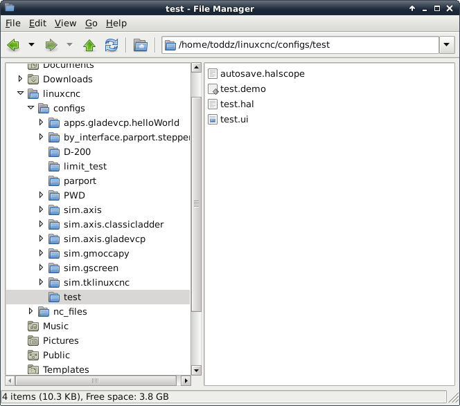
Attachments:
The following user(s) said Thank You: new2linux
Please Log in or Create an account to join the conversation.
- new2linux
- Offline
- Platinum Member
-
Less
More
- Posts: 711
- Thank you received: 9
15 Aug 2022 14:24 #249786
by new2linux
Replied by new2linux on topic Set up using AMC AB15A100 drives, brushed DC motor Prototrak Plus with Encoders
Todd, many thanks! A pic of the error message from opening "test" in terminal. The screen is long so 2 pics.
I am working attaching the short temp wires to TB5 & the P1 connector.
Many thanks!
I am working attaching the short temp wires to TB5 & the P1 connector.
Many thanks!
Please Log in or Create an account to join the conversation.
- Todd Zuercher
-
- Offline
- Platinum Member
-
Less
More
- Posts: 4753
- Thank you received: 1458
15 Aug 2022 16:01 #249794
by Todd Zuercher
Replied by Todd Zuercher on topic Set up using AMC AB15A100 drives, brushed DC motor Prototrak Plus with Encoders
Sorry about that. There is a typo on line 10 of the hal file (test.hal)
The hal file should be
The hal file should be
loadrt threads name1=fast fp1=0 period1=250000 name2=slow period2=1000000

loadrt siggen
loadrt hostmot2
loadrt hm2_pci config=" num_encoders=6 num_pwmgens=0 num_stepgens=5 sserial_port_0=00000x"
setp    hm2_5i25.0.watchdog.timeout_ns 5000000

#loadusr test.ui gladevcp ./test.ui

addf siggen.0.update    slow
addf hm2_5i25.0.read    slow
addf hm2_5i25.0.write    slow

net enable <= test.enable => hm2_5i25.0.7i77.0.1.analogena

setp hm2_5i25.0.encoder.00.counter-mode     0
setp hm2_5i25.0.encoder.00.filter         1
setp hm2_5i25.0.encoder.00.index-invert     0
setp hm2_5i25.0.encoder.00.index-mask         0
setp hm2_5i25.0.encoder.00.index-mask-invert     0
setp hm2_5i25.0.encoder.00.scale          -27500

net x-output <= siggen.0.square => hm2_5i25.0.7i77.0.1.analogout0

net freq <= test.frequency-f => siggen.0.frequency
net amp    <= test.amplitude-f => siggen.0.amplitude
net offset <= test.offset-f => siggen.0.offset

start

loadusr halscope
The following user(s) said Thank You: new2linux
Please Log in or Create an account to join the conversation.
- Todd Zuercher
-
- Offline
- Platinum Member
-
Less
More
- Posts: 4753
- Thank you received: 1458
15 Aug 2022 16:06 #249795
by Todd Zuercher
Replied by Todd Zuercher on topic Set up using AMC AB15A100 drives, brushed DC motor Prototrak Plus with Encoders
The unknown command "ddf" on line 10, should have been an "addf". The "a" was left off.
The following user(s) said Thank You: tommylight, new2linux
Please Log in or Create an account to join the conversation.
Moderators: piasdom
- Hardware & Machines
- CNC Machines
- Milling Machines
- Set up using AMC AB15A100 drives, brushed DC motor Prototrak Plus with Encoders
Time to create page: 1.522 seconds