- Configuring LinuxCNC
- Configuration Tools
- StepConf Wizard
- Need help setting up parallel port on new build
×
Forum Header
Need help setting up parallel port on new build
- phillc54
-

- Offline
- Platinum Member
-

Less
More
- Posts: 5711
- Thank you received: 2100
19 Aug 2021 08:06 #218122
by phillc54
Replied by phillc54 on topic Need help setting up parallel port on new build
Just one is enough for testing.
Please Log in or Create an account to join the conversation.
- CNCApples
- Offline
- Junior Member
-

Less
More
- Posts: 22
- Thank you received: 0
19 Aug 2021 10:50 #218128
by CNCApples
Replied by CNCApples on topic Need help setting up parallel port on new build
Sorry, the photos didn't attach the photo in my previous reply.
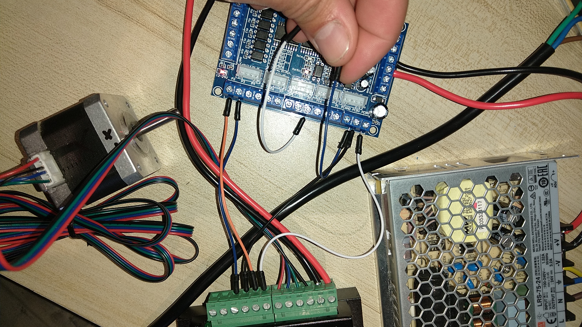
here is a photo of my wiring diagram
here is a photo of my wiring diagram
Please Log in or Create an account to join the conversation.
- phillc54
-
- Offline
- Platinum Member
-
Less
More
- Posts: 5711
- Thank you received: 2100
19 Aug 2021 12:43 #218138
by phillc54
Replied by phillc54 on topic Need help setting up parallel port on new build
Try it with the wire removed from P14.
Please Log in or Create an account to join the conversation.
- CNCApples
- Offline
- Junior Member
-
Less
More
- Posts: 22
- Thank you received: 0
20 Aug 2021 01:25 #218193
by CNCApples
Replied by CNCApples on topic Need help setting up parallel port on new build
So I tried removing ENA- from pin 14,
removing ENA+ from PC5V,
Removing one and not the other, removing both etc with no success yet.
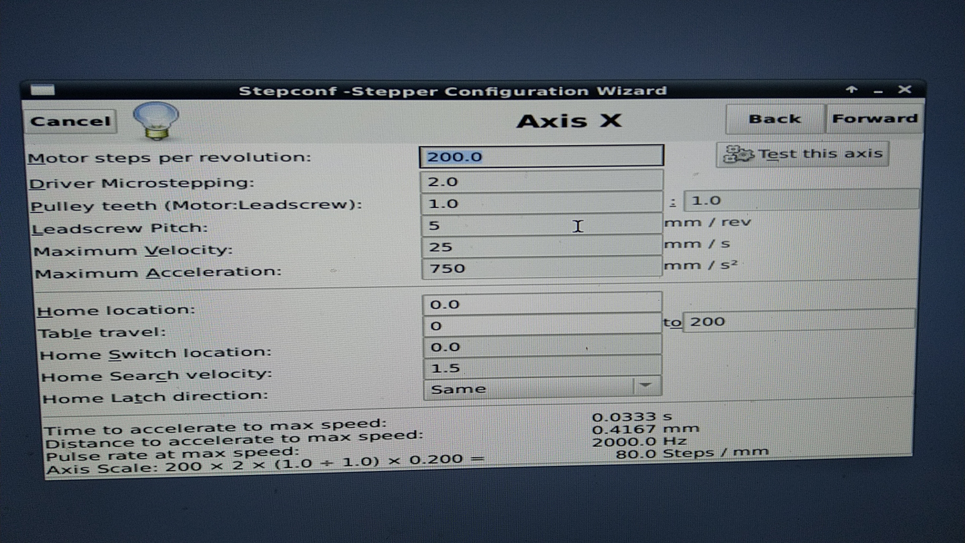
At one point, each time I clicked on "test this axis" the red led on the BOB would light up, I have not been able to recreate this since I powered down to make some connection changes.
Ive backed off a bit since the beginning and am just trying to get one axis moving before I connect more but have hit a wall.
Does my wiring for a single motor look ok? There's 2 photos, one with the ENA +/- connected and one without (I've tried other combinations as well)
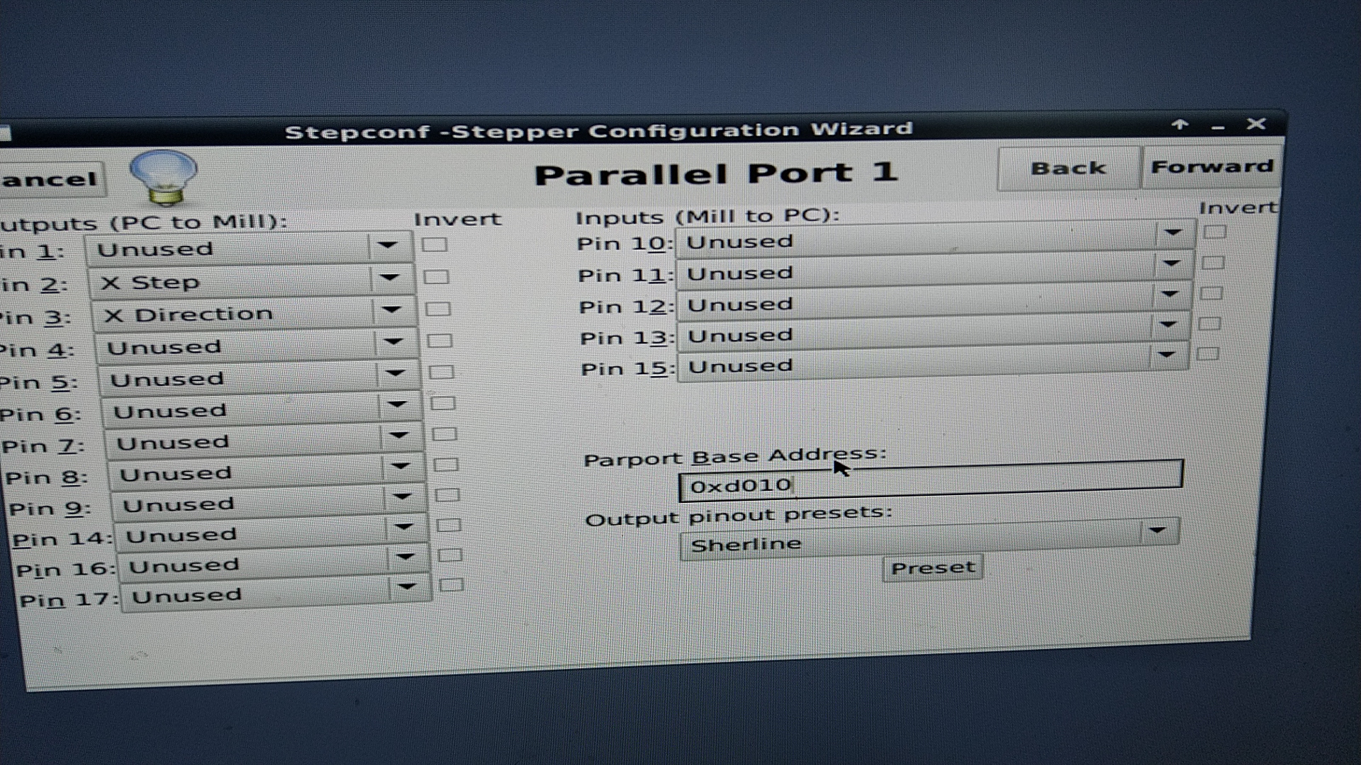
I can't say I know much about Linux but could the pins be addressed wrong on the parallel port card? How would I go about seeing this?
removing ENA+ from PC5V,
Removing one and not the other, removing both etc with no success yet.
At one point, each time I clicked on "test this axis" the red led on the BOB would light up, I have not been able to recreate this since I powered down to make some connection changes.
Ive backed off a bit since the beginning and am just trying to get one axis moving before I connect more but have hit a wall.
Does my wiring for a single motor look ok? There's 2 photos, one with the ENA +/- connected and one without (I've tried other combinations as well)
I can't say I know much about Linux but could the pins be addressed wrong on the parallel port card? How would I go about seeing this?
Please Log in or Create an account to join the conversation.
- CNCApples
- Offline
- Junior Member
-
Less
More
- Posts: 22
- Thank you received: 0
20 Aug 2021 01:30 #218194
by CNCApples
Replied by CNCApples on topic Need help setting up parallel port on new build
Attachments:
Please Log in or Create an account to join the conversation.
- CNCApples
- Offline
- Junior Member
-
Less
More
- Posts: 22
- Thank you received: 0
20 Aug 2021 01:35 #218195
by CNCApples
Replied by CNCApples on topic Need help setting up parallel port on new build
Apologies for the terrible image quality, I realised one of my previous photos didn't include the driver pinout labels
Please Log in or Create an account to join the conversation.
- phillc54
-
- Offline
- Platinum Member
-
Less
More
- Posts: 5711
- Thank you received: 2100
20 Aug 2021 04:35 - 20 Aug 2021 04:35 #218201
by phillc54
Replied by phillc54 on topic Need help setting up parallel port on new build
I use the opposite polarity to you, I don't know if that makes any difference.
This is how my X axis is connected.
Also don't forget to connect the USB port as well as the power supply.
This is how my X axis is connected.
P2 > PUL+
P3 > DIR+
PCGND > PUL- & DIR-
Also don't forget to connect the USB port as well as the power supply.
Last edit: 20 Aug 2021 04:35 by phillc54.
Please Log in or Create an account to join the conversation.
- CNCApples
- Offline
- Junior Member
-
Less
More
- Posts: 22
- Thank you received: 0
20 Aug 2021 04:39 #218202
by CNCApples
Replied by CNCApples on topic Need help setting up parallel port on new build
Cheers for that, try wire it up that way and see how we get on.
Are both your enable pins not connected?
Are both your enable pins not connected?
Please Log in or Create an account to join the conversation.
- phillc54
-
- Offline
- Platinum Member
-
Less
More
- Posts: 5711
- Thank you received: 2100
20 Aug 2021 04:44 #218204
by phillc54
Replied by phillc54 on topic Need help setting up parallel port on new build
They are but only because I use them to switch between a lathe config and a mill config. If I didn't do that then I would leave them disconnected permanently.
Have you also checked that the motor windings are correct. If you disconnect the wires from the driver then the motor should spin by hand easily, if you short the red and blue together it should be hard to move and also if you short the green and black it should be hard to move.
Have you also checked that the motor windings are correct. If you disconnect the wires from the driver then the motor should spin by hand easily, if you short the red and blue together it should be hard to move and also if you short the green and black it should be hard to move.
Please Log in or Create an account to join the conversation.
- CNCApples
- Offline
- Junior Member
-
Less
More
- Posts: 22
- Thank you received: 0
20 Aug 2021 06:35 #218207
by CNCApples
Replied by CNCApples on topic Need help setting up parallel port on new build
The motor spins freely when connected to the drive already. I used a multimeter to check continuity and can confirm the two pairs are correct, red/blue and green/black.
I Have wired the motor with PUL+ on pin2 and DIR+ on pin like in your setup but still no motion.
Instead when I attempt to test the X axis there is a clicking sound and the red relay light on the BOB turns on. Light turns off after I close the test window.
I Have wired the motor with PUL+ on pin2 and DIR+ on pin like in your setup but still no motion.
Instead when I attempt to test the X axis there is a clicking sound and the red relay light on the BOB turns on. Light turns off after I close the test window.
Please Log in or Create an account to join the conversation.
- Configuring LinuxCNC
- Configuration Tools
- StepConf Wizard
- Need help setting up parallel port on new build
Time to create page: 0.677 seconds