Remora - ethernet NVEM cnc board

This is why I need to spend some time cleaning up the repos. The config file you are uploading is not intended for the RT1052 board. Please use the config that correctly selects the GPIO port number.So four development environments later I can now build Remora from source and create my own bin file (just in case anyone else want to give it a go you need the mxuxpresso IDE).
While looking at the source I discovered it is a single bin file for all hardware boards and the config is what defines which hardware variant is used - I was expecting #ifdefs in the code for the hardware. (So now I am confused about why their are different bin files and why remora-rt1052-3.1.2.bin does not work on my NVEM board).
Anyway my new bin created from the main branch at github.com/scottalford75/Remora-RT1052-cpp generates more debug info and allows a config file to upload via TFTP. But there is still an issue. Basically the unit hangs when nvem-full-config.txt or nvem-basic-config.txt is uploaded (it even stops responding to pings). The unit then needs to be erased and flashed to recover (the config survives a power cycle).
This is the output from the debug port. Obviously the ASSERT is being called leading to the unit hanging but why did the X joint load and not the Y joint:1. Loading JSON configuration file from Flash memory
2. Parsing JSON configuration file
Config deserialisation - Deserialization succeeded
3. Board Type: NVEM
4. Configuring threads
Creating timer ISR thread 40000
Creating timer ISR thread 1000
Creating DMA thread 500000
5. Loading modules
Creating a std module
Creating an Ethernet communication monitoring module
Creating Pin @
port = GPIO3
pin = 0
Base thread object
X - Joint 0 step generator
Creating a std module
Creating Pin @
port = GPIO21
pin = 15
Creating Pin @
port = GPIO21
pin = 14
Base thread object
Y - Joint 1 step generator
Creating a std module
Creating Pin @
port = GPIO21
pin = 13
Creating Pin @
port = GPIO21
pin = 12
ASSERT ERROR " instance < ARRAY_SIZE(s_gpioBases) ": file "fsl_gpio.c" Line "60" function name "GPIO_GetInstance"
github.com/scottalford75/Remora-RT1052-c...xCNC/nvem-rt1052.txt
Please Log in or Create an account to join the conversation.
Cool, I'll take a look at the new file. I did get your previous bin file to decompile in Ghidra after playing with starting addresses etc. I'll need to go back and forth between the earlier decompilation and reverse engineering I did to see if the communication protocol has been changed.Thanks Scott,
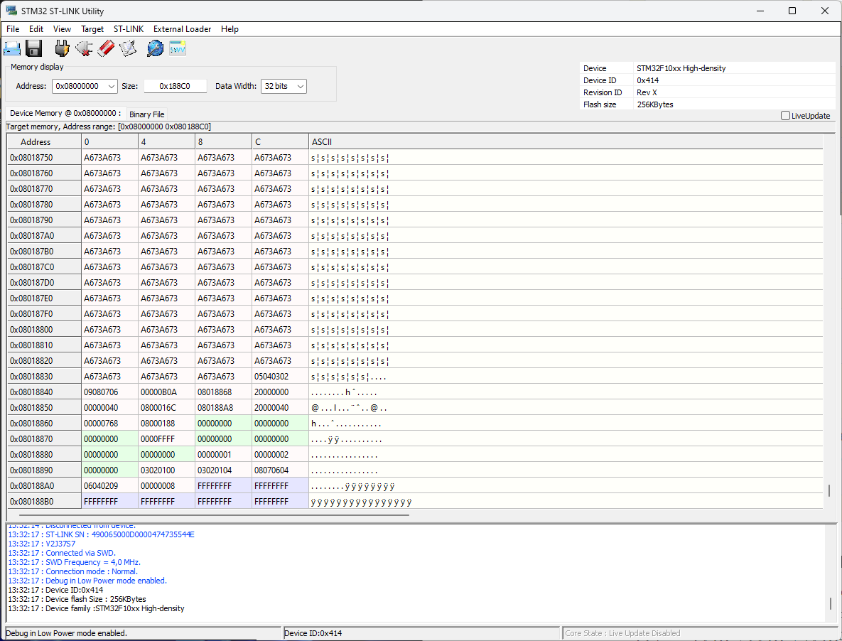
I noticed your image your length is different than mine. After 0x000188B0 in my readout all the data displays as FFFFFFFF. so I set the data size as 0x188C0, which creates a ~236KB hex file. Attaching here and photos of what Isee.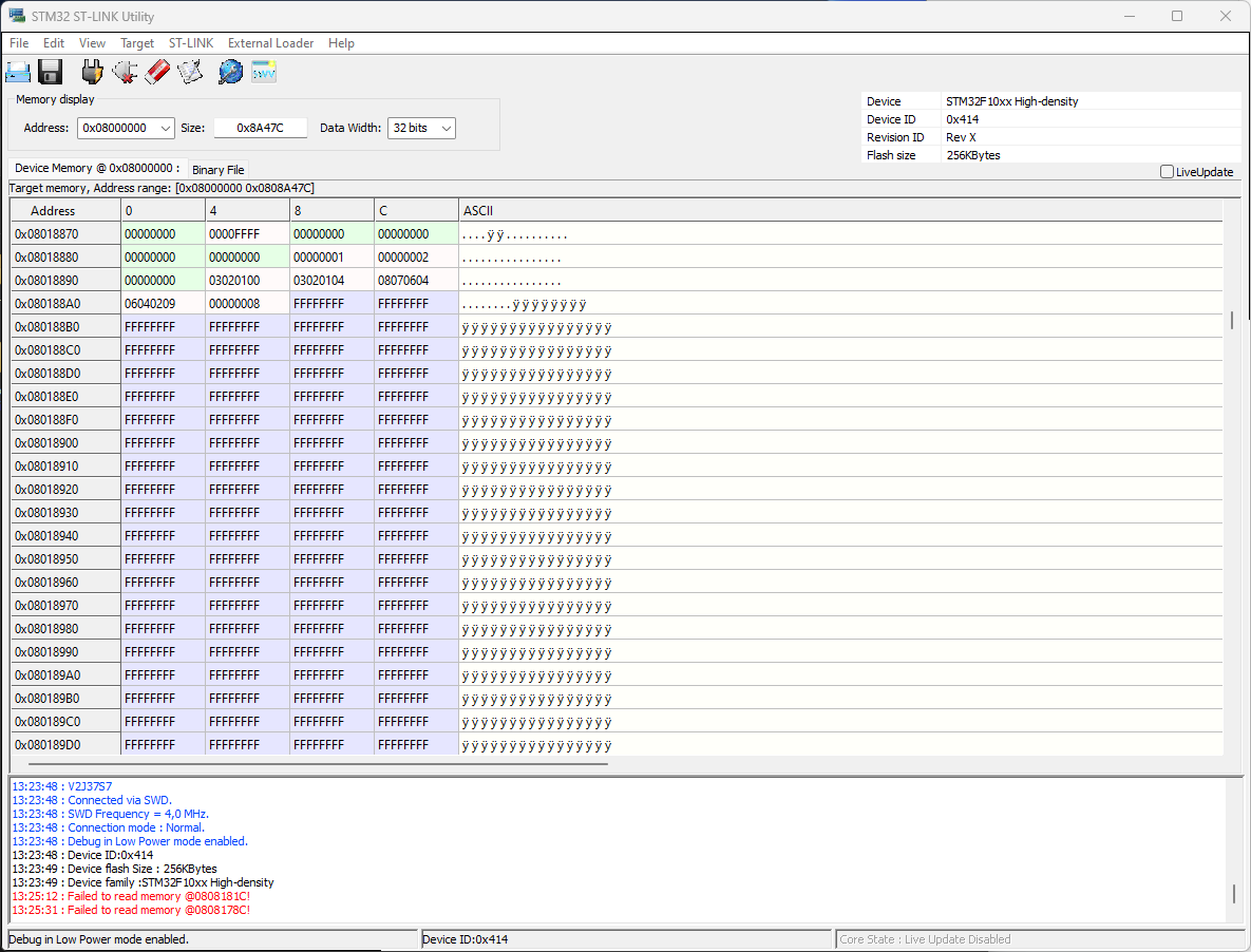
refresh with new size:
Please Log in or Create an account to join the conversation.
Please Log in or Create an account to join the conversation.
I have flashed an RT1052 based NVEM (Marked V5) with the remora-rt1052-3.1.2.bin firmware and uploaded the nvem-rt1052.txt config file to it (minus the NVMPG component).
On boot the debug port shows:
Initializing PHY...
## Entering SETUP state
1. Loading JSON configuration file from Flash memory
2. Parsing JSON configuration file
Config deserialisation - Deserialization succeeded
3. Board Type: NVEM
4. Configuring threads
Creating timer ISR thread 40000
Creating timer ISR thread 1000
Creating DMA thread 500000
5. Loading modules
Creating a std module
Creating an Ethernet communication monitoring module
Creating Pin @
port = GPIO3
pin = 0
Base thread object
X - Joint 0 step generator
Creating a std module
Creating Pin @
port = GPIO1
pin = 22
Creating Pin @
port = GPIO1
pin = 17
Base thread object
Y - Joint 1 step generator
Creating a std module
Creating Pin @
port = GPIO1
pin = 24
Creating Pin @
port = GPIO1
pin = 31
Base thread object
Z - Joint 2 step generator
Creating a std module
Creating Pin @
port = GPIO1
pin = 18
Creating Pin @
port = GPIO1
pin = 25
Base thread object
A - Joint 3 step generator
Creating a std module
Creating Pin @
port = GPIO1
pin = 27
Creating Pin @
port = GPIO1
pin = 21
Base thread object
B - Joint 4 step generator
Creating a std module
Creating Pin @
port = GPIO1
pin = 16
Creating Pin @
port = GPIO1
pin = 23
Base thread object
C - Joint 5 step generator
Creating a std module
Creating Pin @
port = GPIO1
pin = 20
Creating Pin @
port = GPIO1
pin = 19
Servo thread object
FHA
Make Digital Input at pin P3_26
Creating a std module
Creating Pin @
port = GPIO3
pin = 26
Servo thread object
FHB
Make Digital Input at pin P4_30
Creating a std module
Creating Pin @
port = GPIO4
pin = 30
Servo thread object
SRO
Make Digital Input at pin P3_19
Creating a std module
Creating Pin @
port = GPIO3
pin = 19
Servo thread object
SRJ
Make Digital Input at pin P4_20
Creating a std module
Creating Pin @
port = GPIO4
pin = 20
Servo thread object
IN01
Make Digital Input at pin P4_26
Creating a std module
Creating Pin @
port = GPIO4
pin = 26
Servo thread object
IN02
Make Digital Input at pin P4_27
Creating a std module
Creating Pin @
port = GPIO4
pin = 27
Servo thread object
IN03
Make Digital Input at pin P4_21
Creating a std module
Creating Pin @
port = GPIO4
pin = 21
Servo thread object
IN04
Make Digital Input at pin P4_24
Creating a std module
Creating Pin @
port = GPIO4
pin = 24
Servo thread object
IN05
Make Digital Input at pin P4_28
Creating a std module
Creating Pin @
port = GPIO4
pin = 28
Servo thread object
IN06
Make Digital Input at pin P4_25
Creating a std module
Creating Pin @
port = GPIO4
pin = 25
Servo thread object
IN07
Make Digital Input at pin P4_29
Creating a std module
Creating Pin @
port = GPIO4
pin = 29
Servo thread object
IN08
Make Digital Input at pin P4_23
Creating a std module
Creating Pin @
port = GPIO4
pin = 23
Servo thread object
IN09
Make Digital Input at pin P4_31
Creating a std module
Creating Pin @
port = GPIO4
pin = 31
Servo thread object
IN10
Make Digital Input at pin P3_18
Creating a std module
Creating Pin @
port = GPIO3
pin = 18
Servo thread object
IN11
Make Digital Input at pin P3_21
Creating a std module
Creating Pin @
port = GPIO3
pin = 21
Servo thread object
IN12
Make Digital Input at pin P3_20
Creating a std module
Creating Pin @
port = GPIO3
pin = 20
Servo thread object
CIN
Make Digital Input at pin P4_18
Creating a std module
Creating Pin @
port = GPIO4
pin = 18
Servo thread object
XIN
Make Digital Input at pin P4_17
Creating a std module
Creating Pin @
port = GPIO4
pin = 17
Servo thread object
YIN
Make Digital Input at pin P4_16
Creating a std module
Creating Pin @
port = GPIO4
pin = 16
Servo thread object
ZIN
Make Digital Input at pin P4_15
Creating a std module
Creating Pin @
port = GPIO4
pin = 15
Servo thread object
AIN
Make Digital Input at pin P4_14
Creating a std module
Creating Pin @
port = GPIO4
pin = 14
Servo thread object
X100IN
Make Digital Input at pin P4_13
Creating a std module
Creating Pin @
port = GPIO4
pin = 13
Servo thread object
X10IN
Make Digital Input at pin P4_12
Creating a std module
Creating Pin @
port = GPIO4
pin = 12
Servo thread object
EP
Make Digital Input at pin P4_11
Creating a std module
Creating Pin @
port = GPIO4
pin = 11
Servo thread object
INDEX
Make Digital Input at pin P3_22
Creating a std module
Creating Pin @
port = GPIO3
pin = 22
Servo thread object
WHA
Make Digital Input at pin P3_16
Creating a std module
Creating Pin @
port = GPIO3
pin = 16
Servo thread object
WHB
Make Digital Input at pin P3_17
Creating a std module
Creating Pin @
port = GPIO3
pin = 17
Servo thread object
OT01
Make Digital Output at pin P4_01
Creating a std module
Creating Pin @
port = GPIO4
pin = 1
Servo thread object
OT02
Make Digital Output at pin P4_02
Creating a std module
Creating Pin @
port = GPIO4
pin = 2
Servo thread object
OT03
Make Digital Output at pin P4_03
Creating a std module
Creating Pin @
port = GPIO4
pin = 3
Servo thread object
OT04
Make Digital Output at pin P4_04
Creating a std module
Creating Pin @
port = GPIO4
pin = 4
Servo thread object
OT05
Make Digital Output at pin P4_05
Creating a std module
Creating Pin @
port = GPIO4
pin = 5
Servo thread object
OT06
Make Digital Output at pin P4_06
Creating a std module
Creating Pin @
port = GPIO4
pin = 6
Servo thread object
OT07
Make Digital Output at pin P4_07
Creating a std module
Creating Pin @
port = GPIO4
pin = 7
Servo thread object
OT08
Make Digital Output at pin P4_08
Creating a std module
Creating Pin @
port = GPIO4
pin = 8
Servo thread object
OT09
Make Digital Output at pin P4_09
Creating a std module
Creating Pin @
port = GPIO4
pin = 9
Servo thread object
OT10
Make Digital Output at pin P4_10
Creating a std module
Creating Pin @
port = GPIO4
pin = 10
Servo thread object
Spindle PWM
Creating a std module
## Entering START state
Starting the BASE thread
Registering interrupt for interrupt number = 100
configuring Timer 1
timer started
Starting the SERVO thread
Registering interrupt for interrupt number = 101
configuring Timer 2
timer started
## Entering IDLE state
I install the remora-eth-3.0.c component and can start Linuxcnc using the remora-rt1052-basic profile (having changed the hal file to use remora-eth3.0 module rather than the (old?) remora-nv module).
I can then connect linuxcnc to the NVEM and one of the LED's on the NVEM board turns on or off depending on if I enable or disable linuxcnc.
But when I try to move the x or y stepper nothing happens. Also if I view the remora.inputs I do not see any changes in response to pulling the inputs to gnd. If I look at the remora.status using the hal viewer it shows the board as connected. If I look at the remora counters using the HAL viewer I can see them incrementing.
So on the face of it it looks like the board is connected but not actually doing anything.
So what have I missed?
Note: I am assuming the remora.inputs should be updated in the hal viewer even if the hal file was wrong.
Please Log in or Create an account to join the conversation.
If LinuxCNC is showing motion in the gremlin view then I would suspect a driver wiring issue.
For the IO this only works when the board is not in E-stop condition. ie connection active.
Please Log in or Create an account to join the conversation.
I have a problem with my STM32F207 board. I cannot get the voltage on physical out pin cnahged. When I for example setp remora.output.3 to logical "1" the voltage does not change on a physical pin, while in HAL Configuration it sets to "True".
The board is configured with "nvem-full-config.txt" from github.com/scottalford75/Remora-NVEM/blo...nvem-full-config.txt
Does anyone knows what may be a reason for this behaviour?
Please Log in or Create an account to join the conversation.
Please Log in or Create an account to join the conversation.