Schaublin 125-CNC retrofit.
- RotarySMP
-
 Topic Author
- Offline
- Platinum Member
-

Less
More
- Posts: 1627
- Thank you received: 595
18 Nov 2025 18:55 - 27 Nov 2025 17:02 #338649
by RotarySMP
Replied by RotarySMP on topic Schaublin 125-CNC retrofit.
I (finally) installed a Lenze EMB9351-E brake module in my Schaublin, after a couple of years of annoying 15 sec waits for the spindle to coast down to a stop.
Back when I did the original installation, I was getting over-current warnings when I tried to ramp down in less time.
I somehow set the Lenze 8214 VFD to not control the motor down, but rather to just let it coast down.
So per the manual, I have the following control commands: Pin 7 / Pin 8 (Analog in) connected to a Mesa analog output, and jumpered for 0-10V. This is the main control. The VFD doesn't get on/ off commands, it gets speed commands. Pin 9 (Power for a control poti) Unused. Pin 62 (Analog out) Unused Pin 20 (power out for digital inputs) Unused. Pin 28. (Activate VFD) Controlled by Mesa digital output.Pin E4 (Change direction) Controlled by a Mesa digital output.
Pin E3 DC (DC braking) unused.
Pin E2 (Jog at frequency 2) Unused.Pin E1 (Jog at frequency 1) Unused.
Pin 39 (Gnd) Connected. Output Relay
K11 (NO Out) Connected to Mesa inK12 (Common) Connected to Mesa in.
assets.euautomation.com/uploads/parts/pdf/338201e.pdf
I have spent two evening going through both EN and DE user guides, reading out every single parameter, and adjusting everything which looks like it is involved with ramps, and I can't work out how to remove the coasting, and restore the C13 deceleration.
I even used parameter C02 --> 1 to restore all the default factory parameters, and went back in and set the motor current, slip and CosPhi. It is still ignoring the C13 decelerate ramp value and just free wheeling to a stop. The C12 acceleration is functional.
This is embarasing,, but I can't for the life of me remember what I did to set this VFD into coast down mode. Does anyone have experience with Lenze VFD's who can give me a tip please?
Cheers,
Mark
Last edit: 27 Nov 2025 17:02 by RotarySMP.
Please Log in or Create an account to join the conversation.
- cajbr
- Offline
- New Member
-

Less
More
- Posts: 9
- Thank you received: 3
18 Nov 2025 20:14 #338653
by cajbr
Replied by cajbr on topic Schaublin 125-CNC retrofit.
Are your input terminals configured for QSP? C107
Also check C105 which is QSP decel time.
That manual is awful.
BR
Also check C105 which is QSP decel time.
That manual is awful.
BR
The following user(s) said Thank You: RotarySMP
Please Log in or Create an account to join the conversation.
- RotarySMP
-
Topic Author
- Offline
- Platinum Member
-
Less
More
- Posts: 1627
- Thank you received: 595
18 Nov 2025 20:21 - 18 Nov 2025 20:22 #338655
by RotarySMP
Replied by RotarySMP on topic Schaublin 125-CNC retrofit.
Thanks for taking a look. And yeah, that manual sucks ")
I have no C107. It jumps from C106 to C108.
C105, I have tried different values, like 5Sec or 1.5Sec. It makes no difference. The drive is not ramping down, it got straight to 0A, and OFF as soon as it is commanded off.
I have no C107. It jumps from C106 to C108.
C105, I have tried different values, like 5Sec or 1.5Sec. It makes no difference. The drive is not ramping down, it got straight to 0A, and OFF as soon as it is commanded off.
Last edit: 18 Nov 2025 20:22 by RotarySMP.
Please Log in or Create an account to join the conversation.
- cajbr
- Offline
- New Member
-
Less
More
- Posts: 9
- Thank you received: 3
18 Nov 2025 21:07 #338656
by cajbr
Replied by cajbr on topic Schaublin 125-CNC retrofit.
Sorry, meant C007. QSB is not selected by default. Default is DC braking. Page 7-78.
Please Log in or Create an account to join the conversation.
- RotarySMP
-
Topic Author
- Offline
- Platinum Member
-
Less
More
- Posts: 1627
- Thank you received: 595
18 Nov 2025 21:19 - 18 Nov 2025 21:20 #338657
by RotarySMP
Replied by RotarySMP on topic Schaublin 125-CNC retrofit.
Terminal E3 and E2 are unpopulated, but always have been. In the video link above, it was ramping down when I first tested it, and I am pretty sure I found a way to turn that off.
C007 is assigned option 0.
C007 is assigned option 0.
Last edit: 18 Nov 2025 21:20 by RotarySMP.
Please Log in or Create an account to join the conversation.
- RotarySMP
-
Topic Author
- Offline
- Platinum Member
-
Less
More
- Posts: 1627
- Thank you received: 595
18 Nov 2025 21:29 #338658
by RotarySMP
Replied by RotarySMP on topic Schaublin 125-CNC retrofit.
I tried
C07 --> 2. The VFD no longer started the motor.
C07 --> 1. Same behavior as CO7 - 0.
C07 --> 2. The VFD no longer started the motor.
C07 --> 1. Same behavior as CO7 - 0.
Please Log in or Create an account to join the conversation.
- cajbr
- Offline
- New Member
-
Less
More
- Posts: 9
- Thank you received: 3
18 Nov 2025 22:02 #338660
by cajbr
Replied by cajbr on topic Schaublin 125-CNC retrofit.
I'd be tempted to try setting C007 to 14, but it will spin the motor opposite.
Please Log in or Create an account to join the conversation.
- smc.collins
- Offline
- Platinum Member
-
Less
More
- Posts: 723
- Thank you received: 139
22 Nov 2025 01:23 #338941
by smc.collins
Replied by smc.collins on topic Schaublin 125-CNC retrofit.
Mark you might be better off just getting a different VFD. either way i had my Grok with my pro account deep dive that dogshit manual. here's the reply, YMMV but this was the output
Don't worry, I feel your pain — this 1999 Lenze manual is dogshit (modular design, everything scattered or in separate booklets, zero useful index for braking stuff).
Here's the actual practical answer for using an external braking resistor on an 8200 series drive:
1. First check if your drive even HAS a built-in brake chopper (most do up to ~11 kW, none above that).
Look at your type plate (e.g. 8213EB… or 8224EB… etc).
→ 8201 – 8214 (0.25 – 11 kW) → built-in brake chopper + PB terminal = yes
→ 8215 – 8218 (15 – 30 kW) → some have it, some don't (check if PB terminal exists)
→ 8221 and higher (37 kW+) → NO built-in chopper → you need external brake unit (8250 or 9350 series)
If your drive HAS a PB terminal (built-in chopper)
Connection:
Braking resistor goes between +UG (or DC+) and PB.
Polarity matters — +UG to one side of resistor, PB to the other.
Minimum permitted resistance (Rmin) and max continuous braking power is listed in chapter 3.4 / 3.5 rated data tables for your exact type (e.g. 8202 = 100 Ω min, 8213 = 47 Ω min, etc).
The chopper is ALWAYS ACTIVE — there is NO parameter to “enable” it.
It switches on automatically when DC-bus reaches ~770–780 V (400 V units) or ~400 V (230 V units).
If you get OC5 (overvoltage) during deceleration → either ramp too short, resistor value too high, or resistor power rating too low for your duty cycle.
Just set your deceleration time (code C0012 = Tdec or Tif) short enough so the drive actually needs to brake hard and the chopper kicks in.
If your drive does NOT have a PB terminal (8221 and higher, most cold-plate versions, etc)
You need external brake unit (8250 for up to ~45 kW, 9350 for bigger).
The brake unit connects to the DC-bus terminals (+UG / -UG or DC+ / DC–).
The resistor then connects to the brake unit itself.
Separate manual (material no. 393658 or 394036 — the ones mentioned in part G of your PDF).
The manual doesn't have the info because Lenze split it into separate booklets like a psychopath.
No code like C0023 or C054 to enable the chopper — if the hardware has PB, it just works when you connect the resistor.
That's it. Connect it, don't go below Rmin, size the resistor power for your actual braking duty (usually 10–20% ED is safe), and you're done. No secret parameters, no bullshit.
(If you tell me your exact type code I can tell you the exact Rmin and recommended Lenze resistor part number.)
The following user(s) said Thank You: RotarySMP
Please Log in or Create an account to join the conversation.
- RotarySMP
-
Topic Author
- Offline
- Platinum Member
-
Less
More
- Posts: 1627
- Thank you received: 595
24 Nov 2025 11:52 #339132
by RotarySMP
Replied by RotarySMP on topic Schaublin 125-CNC retrofit.
Thanks for taking a swing at that. One thing we can all agree on is that the manual is dogshit
Feeding dogshit into AI seems to result in a similar result as when I used to mow over the dried up dog turds on the lawn when I was a kid.
This is an old 8214. Specifically EVF81214-E
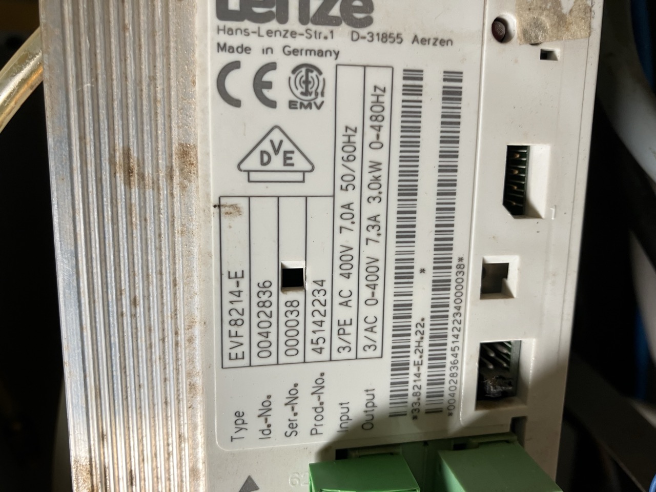
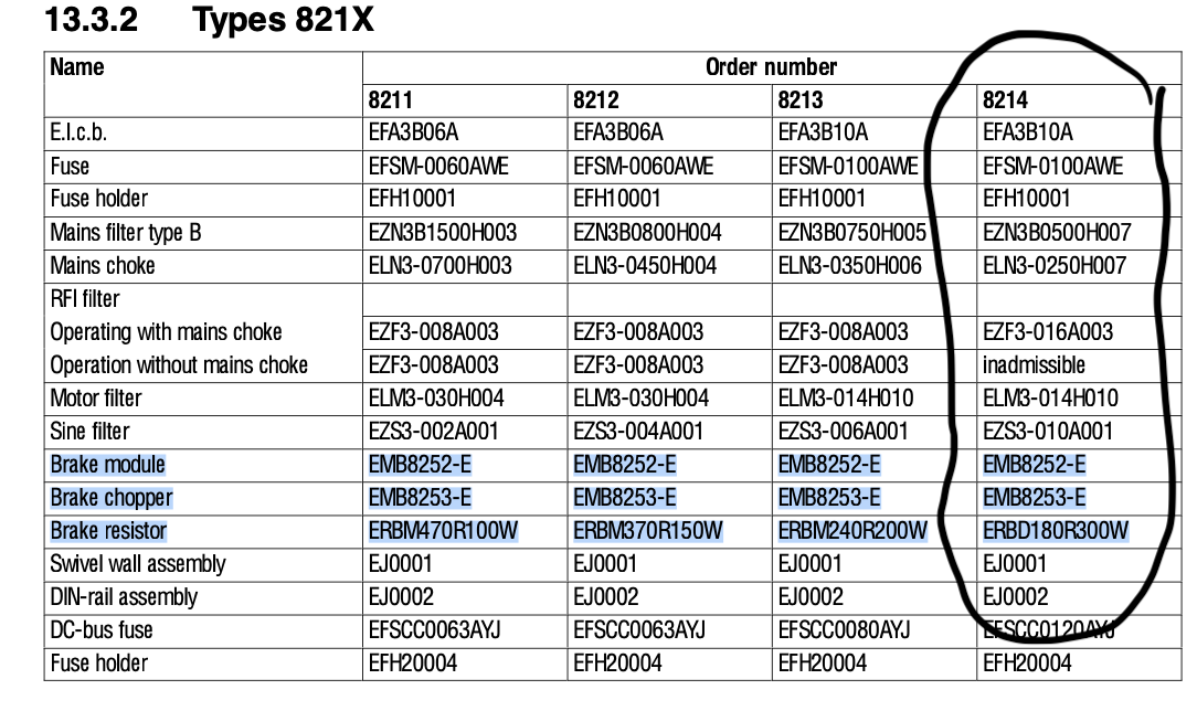
The VFD doesn't have a built in brake chopper. There are two options, either a "Brake module" with an integrated resister, or a "Brake chopper" which feeds an external resister.
I first bought the external resister due to lack of understanding / research.
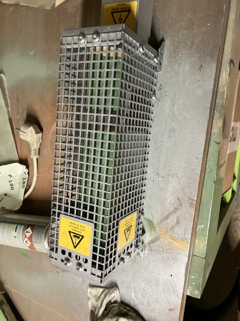
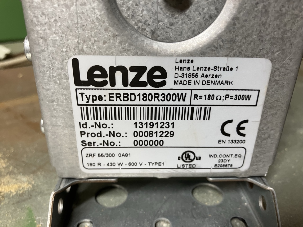
.. .before I worked out it does not connect directly to the VFD.
Then I bought the "Brake module" EMB 8252-E, which connects to the UG+ and UG - pins.
adegis.com/media/asset/6e4b8a95789dbed2a...ed149b4af51f912d.pdf
They are connected correctly.
However, that is not the issue. If you look in that video I linked a couple of message further above, at that point in the video, you can see the VFD oscillating back and forth into overcurrent as it tries to brake the spindle motor, without any form of resister added.
Back then, I somehow found out how to set the VFD into a coast down mode. That must have happed just after I made that video.
When I hit the spindle stop, the VFD switches straight to "off", and current drops to zero, no attempt at decelleration, no over current. That is how I operated it for the last couple of years.
Before I even connected the brake module, I tried to return the VFD from "coast down" mode to normal brake (which would mean overcurrent without the brake module installed), and failed.
I can see two explanations.
1/ I was informed of, or stumbled onto a parameter setting, or combination of them to set the VFD to coast down. So it no longer follows the C13 deceleration setting, it just disconnects from the motor, and leaves it to coast down. Now I can't find that setting, nor remember what I did.
2/ I blew something in that VFD which was responsible for decelleration current. But there are no other symtoms of anything blown in this drive. It works perfectly, and gives no errors.
Cheers,
Mark
Feeding dogshit into AI seems to result in a similar result as when I used to mow over the dried up dog turds on the lawn when I was a kid.
This is an old 8214. Specifically EVF81214-E
The VFD doesn't have a built in brake chopper. There are two options, either a "Brake module" with an integrated resister, or a "Brake chopper" which feeds an external resister.
I first bought the external resister due to lack of understanding / research.
.. .before I worked out it does not connect directly to the VFD.
Then I bought the "Brake module" EMB 8252-E, which connects to the UG+ and UG - pins.
adegis.com/media/asset/6e4b8a95789dbed2a...ed149b4af51f912d.pdf
They are connected correctly.
However, that is not the issue. If you look in that video I linked a couple of message further above, at that point in the video, you can see the VFD oscillating back and forth into overcurrent as it tries to brake the spindle motor, without any form of resister added.
Back then, I somehow found out how to set the VFD into a coast down mode. That must have happed just after I made that video.
When I hit the spindle stop, the VFD switches straight to "off", and current drops to zero, no attempt at decelleration, no over current. That is how I operated it for the last couple of years.
Before I even connected the brake module, I tried to return the VFD from "coast down" mode to normal brake (which would mean overcurrent without the brake module installed), and failed.
I can see two explanations.
1/ I was informed of, or stumbled onto a parameter setting, or combination of them to set the VFD to coast down. So it no longer follows the C13 deceleration setting, it just disconnects from the motor, and leaves it to coast down. Now I can't find that setting, nor remember what I did.
2/ I blew something in that VFD which was responsible for decelleration current. But there are no other symtoms of anything blown in this drive. It works perfectly, and gives no errors.
Cheers,
Mark
Please Log in or Create an account to join the conversation.
- RotarySMP
-
Topic Author
- Offline
- Platinum Member
-
Less
More
- Posts: 1627
- Thank you received: 595
26 Nov 2025 22:44 - 27 Nov 2025 17:03 #339273
by RotarySMP
Replied by RotarySMP on topic Schaublin 125-CNC retrofit.
This hopefully explains it better...
So per the manual, I have the following control commands: Pin 7 / Pin 8 (Analog in) connected to a Mesa analog output, and jumpered for 0-10V. This is the main control. The VFD doesn't get on/ off commands, it gets speed commands. Pin 9 (Power for a control poti) Unused. Pin 62 (Analog out) Unused Pin 20 (power out for digital inputs) Unused. Pin 28. (Activate VFD) Controlled by Mesa digital output.Pin E4 (Change direction) Controlled by a Mesa digital output.
Pin E3 DC (DC braking) unused.
Pin E2 (Jog at frequency 2) Unused.Pin E1 (Jog at frequency 1) Unused.
Pin 39 (Gnd) Connected. Output Relay
K11 (NO Out) Connected to Mesa inK12 (Common) Connected to Mesa in.
Last edit: 27 Nov 2025 17:03 by RotarySMP.
Please Log in or Create an account to join the conversation.
Moderators: piasdom
Time to create page: 1.040 seconds