Is the Ecoca EL4610e a good candidate for a retrofit?
- MulBe039
- Offline
- New Member
-

- Posts: 13
- Thank you received: 4
the machine seems to have a gearbox spindle and though the spindle drive mostly handles it transparently for the controller, i will probably need to add a few HAL pins to the driver for gear selection
The gears are shifted manually via two levers:
one that has two positions H, ML
the other has three positions L, M, H
There are however only three valid lever combinations that are printed on the lathe itself.
With the documentation that came with this machine there was also a booklet called "Parameter List" - dm17ry indicated in one of his mails that these are needed to properly set up the servo drives. I will scan and upload this document as soon as possible so that anyone can acces it.
I also have mechanical drawings and a spare parts manual for the machine, however some of the drawings are a3 format and would be problematic to scan on my home scanner, so i will only upload those if there is real interest in them.
and porting/re-implementing the ladder will require some effort... but all should be doable
I hadn't even considered that option, in my mind I was already preparing to start from scratch, pull out all the wiring and see what I could come up with myself. But this sounds indeed like the much more sensible option.
Do you have any links/information/documentation that I could check out to learn about how to do this?
Also, given that the controller in this lathe is currently in working condition, do you know if there is a way to maybe backup/extract the ladder from the machine? Is this worth doing? Would this help in any way with the porting? Do any of you think this information could be useful to anyone?
Please Log in or Create an account to join the conversation.
- dm17ry
-

- Offline
- Elite Member
-

- Posts: 203
- Thank you received: 88
i'm far from being a big fan of that ladder logic notation. it's far easier for me to rewrite everything in c or python. so i myself would definitely would start from scratch and won't try to port anything from the meldasmagic64 to the linuxcnc. but being able to look at what they have there would be useful.
and yeah, please post that "parameter list" tables - it should give a good idea about the machine configuration and i will probably be able to give some more specific suggestions how to get at it with the linuxcnc retrofit.
Please Log in or Create an account to join the conversation.
- MulBe039
- Offline
- New Member
-
- Posts: 13
- Thank you received: 4
i'm far from being a big fan of that ladder logic notation. it's far easier for me to rewrite everything in c or python. so i myself would definitely would start from scratch and won't try to port anything from the meldasmagic64 to the linuxcnc. but being able to look at what they have there would be useful.
Yeah not a huge fan either. I get why the notation was invented and why it was popular at the time, but it really should have been phased out about 40 years ago. It is obviously good that the knowledge about this is still out there if you need it for working on old equipment, but I honestly don't get why we even bother teaching this stuff anymore.
So correct me if I got anything wrong here:
The servodrives and the encoders will be handled by your board&.software. These receive instructions from linuxCNC based on the entered gcode.
This includes selected gear detection, absolute position of the machine and the spindle index pulse as well as the pulse generation.
As far as operation-critical stuff goes, that leaves:
E-stops
safetyswitches on the Door and the Chuck-guard
Limitswitch on the tailstock
Coolant pump
Sensors for pressure temperature and oil level for the headstock lubrication as well as the associated pump
" " " for the ways lubrication " " "
I'd like to handle the E-stops outside of software, so that they work reliably even when the computer has problems. For this I will take a closer look at the relay board that they are currently wired into and see if I can't reuse anything around there.
Or is there a sort of 'standard procedure' here that is used with linuxcnc?
I will need to identify how these pressure- temperature- and oil-level sensors operate and figure out how to easily inteface these with the new controller. I'm assuming they're probably analog.
Do yo perhaps recognize in the parameter list (attached below) what the treshold values for these sensors are for which they trigger?
Then there are a few features that have proven to be quite useful on the physical interface and which I would like to preserve:
Two integrated MPGs and a Joystick to position the machine and do basic 'manual' operations
A selector for the jog increments of the MPGs
for this I have already seen tutorials on how to implement it around here on the forum, so figuring this out shouldn't be too hard.
A button which indexes the spindle and holds it in place
A physical button to stop the spindle
The rest of the I/O really is only is a bunch of buttons to facilitate operation in semi-automated mode and in manual mode.
It would be nice to maintain the functionality, but they are not very far on top of my priority list.
The way I currently see it, I think the most sensible way to go about this would be to take out the BASE I/O unit & the REMOTE I/O UNIT, hook up a step down converter to the 24VDC that energize all these circuits to prevent it from frying the control electronics and hook up all the buttons from the console directly to an I/O card or a parallel port.
If I understand correclty, what I would then need to do, would be to igure out how to add and configure the corresponding pins to the HAL and have them deploy macros when they are pressed.
Am I thinking in the right direction or am I making a major rookie mistake here?
Parameter list for the Ecoca 460 Series:
drive.google.com/file/d/1T9jkDEeHv4I-D1q...P3Q/view?usp=sharing
By the way, I had a look around in the usual places for used electronics, and found someone offering:
mesa 5i24-16 Anything I/O PCI card + MESA 7i42TA Breakout/Protection card
Apparently they are unopened, and the price was right, so apparently this is what I am working with now
Please Log in or Create an account to join the conversation.
- dm17ry
-
- Offline
- Elite Member
-
- Posts: 203
- Thank you received: 88
The servodrives and the encoders will be handled by your board&.software. These receive instructions from linuxCNC based on the entered gcode.
This includes selected gear detection, absolute position of the machine and the spindle index pulse as well as the pulse generation.
servos are in position control mode. they accept a 32-bit position command and return a 32-bit feedback. plus a number of boolean flags. interfacing to linuxcnc is really straightforward, no linuxcnc's PIDs or stepgens are used. basically a few HAL connections like:
joint.x.amp-enable-out => nyx.0.servo-xx.enable
joint.x.motor-pos-cmd => nyx.0.servo-xx.pos-cmd
joint.x.motor-pos-fb <= nyx.0.servo-xx.pos-fb
joint.x.amp-fault-in <= nyx.0.servo-xx.alarm
the spindle is similar, but with a speed command instead. the driver also provides a spindle encoder interface in linuxcnc style with a index-enable pin. see sample configs...
there're number of points where the e-stop can be wired... yeah, have a look first at the machine schematics and ladder how they do it.I'd like to handle the E-stops outside of software, so that they work reliably even when the computer has problems. For this I will take a closer look at the relay board that they are currently wired into and see if I can't reuse anything around there.
Or is there a sort of 'standard procedure' here that is used with linuxcnc?
i doubt there's any analog sensors - pretty sure they all end up with a discrete 24VDC outputsI will need to identify how these pressure- temperature- and oil-level sensors operate and figure out how to easily inteface these with the new controller. I'm assuming they're probably analog. Do yo perhaps recognize in the parameter list (attached below) what the treshold values for these sensors are for which they trigger?
i would definitely keep 24VDC circuits as they are and use compatible I/O cards. mesa or my YIO.The way I currently see it, I think the most sensible way to go about this would be to take out the BASE I/O unit & the REMOTE I/O UNIT, hook up a step down converter to the 24VDC that energize all these circuits to prevent it from frying the control electronics and hook up all the buttons from the console directly to an I/O card or a parallel port.
another compelling option i'm thinking about is to keep the base and RIO units in place and interface them directly. they use a half-duplex serial rs-485 interface, just like my YIO modules. i have an idea about the protocol used. so theoretically i can implement it in the card firmware...
Please Log in or Create an account to join the conversation.
- MulBe039
- Offline
- New Member
-
- Posts: 13
- Thank you received: 4
servos are in position control mode. they accept a 32-bit position command and return a 32-bit feedback. plus a number of boolean flags. interfacing to linuxcnc is really straightforward, no linuxcnc's PIDs or stepgens are used. basically a few HAL connections like:
joint.x.amp-enable-out => nyx.0.servo-xx.enable
joint.x.motor-pos-cmd => nyx.0.servo-xx.pos-cmd
joint.x.motor-pos-fb <= nyx.0.servo-xx.pos-fb
joint.x.amp-fault-in <= nyx.0.servo-xx.alarm
the spindle is similar, but with a speed command instead. the driver also provides a spindle encoder interface in linuxcnc style with a index-enable pin. see sample configs...
Out of curisosity: Would it be possible to put the spindle in absolute position mode as well? Further down the line I was wondering if it might then be possible to use the spindle as an A axis and an active tool on the toolpost to do some basic milling on parts?
I guess to maintain proper positioning I'd have to add a physical break at some point to maintain the exact spindle position- that is something I will worry about when I come to that point, just wondering if it is possible in software to position the spindle to a precise position, or if the drives will not support this?
I would definitely keep 24VDC circuits as they are and use compatible I/O cards. mesa or my YIO.1
Yeah the thing is that while this might be the most straightforward option, it also seems like a very expensive option.
There's a total of 54 "buttons" (counting each position of the rotary switches as one button) on the two consoles. So that means I'd need 54 24V tolerant I/O ports. If I understand correctly, the correct MESA board for this application would be a 7i64 which costs ~200$ plus shipping and I would theoretically need 3 of those.
Now I could drop the number of pins down to 48 by omitting some of the 'less useful' features, then I would only need 2 Boards, but that is still 400$.
Plus I'd be paying for 48 Outputs that I don't "really" need. Currently the machine is set up in a way that some buttons are illuminated when pressed their mode is activated so I guess I could use them for that, but it seems like a biit of a waste to be honest.
If I went with your YIO cards, the cost comes to:
Base YIO Module 80$
3* 16 Channel Input board (48 Cannels) 240$
Total 320$ - a bit cheaper than the MESA solution, but then again I wouldn't have the outputs if I ever did decide to use them.
It just seems like a lot of money for something as basic as detecting and processing simple button-presses, which could ultimately also all be added as virtual buttons in the interface with custom macros.
Since none of these button-presses are super timing-critical and only serve to simplify user-interaction with the machine, I was wondering if it might not be possible to build a board with a few (7 in my case) 74HC166D daisy-chained together (PISO shift registers) and optically isolate their inputs.
You could then read the state of this board periodically as a string of bits and put the output trough a state-machine which tells linuxCNC what buttons are currently pressed and how to treat these outputs.
For the buttons that have lights in them, these could be replaced with daisy-chained WS2812B LEDs. Would also add the possibility to indicate different machine-states via color-codes.
This solution would come out at a fraction of the price, only use 6 I/O pins which could be hooked up directly to an FPGA card and could be scaled almost indefintely. Perhaps this is also something that the entire community could benefit from in the long run?
I am however not sure if this is something that can easily be interfaced with linuxcnc, I know assembly and have played around with a few arduinos etc. but have basically zero knowledge about linux. I would assume it shouldn't be that hard and is probably something that you can do already, you just need to know where to look.
another compelling option i'm thinking about is to keep the base and RIO units in place and interface them directly. they use a half-duplex serial rs-485 interface, just like my YIO modules. i have an idea about the protocol used. so theoretically i can implement it in the card firmware...
The idea is indeed very compelling, especially in the short term, and it will certainly make your card even more useful to anyone who is looking for a drop-in replacement for their MELDAS cards.
If this is something that you are willing/able to do, I will gladly assist you in any way that I can.
However, the main reason for this entire project is to get the machine to a point where I don't have to rely on the availability of legacy hardware anymore if something ever decides to fail. So I'm not sure if this is necessarily the right option to persue long-term. I will have a look at the state of these boards and their layout, potentially assesing how failure-proof they look to me.
This will however have to wait at least until the 20th of January, before that I have no access to the machine's electrical cabinet.
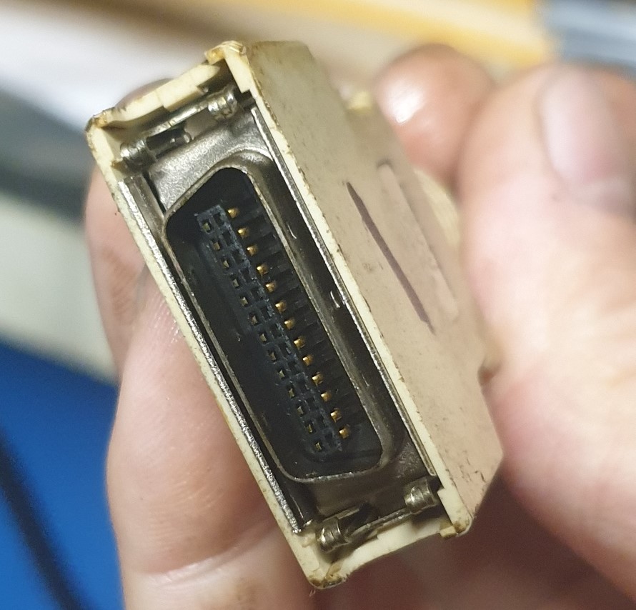
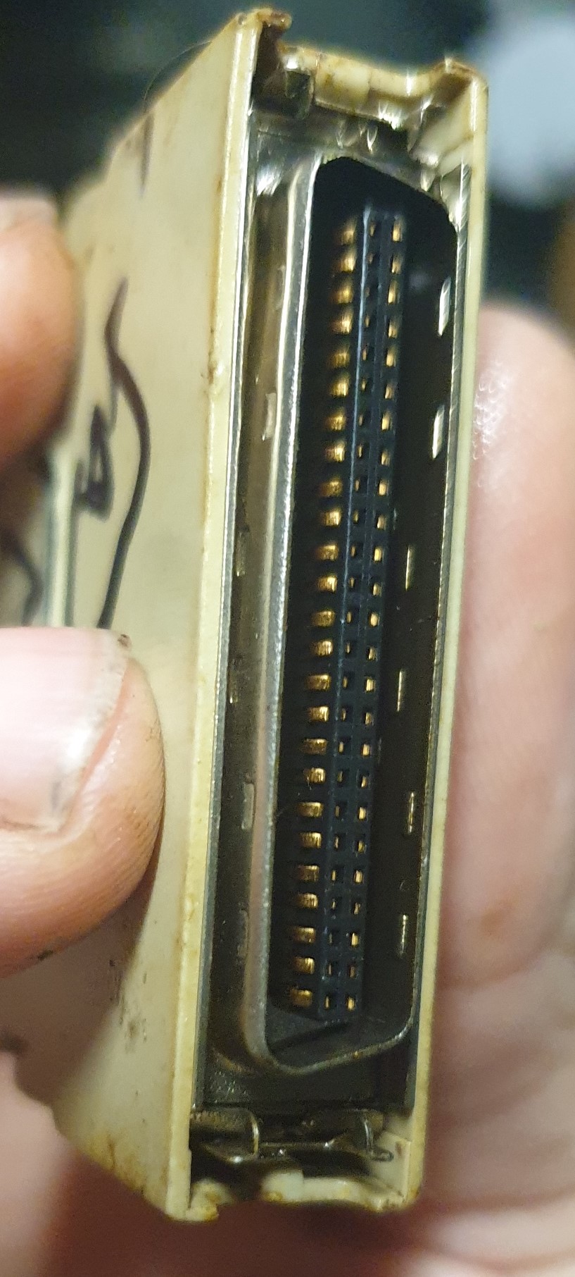
Until then, if it is of any help, here are pictures of the two connectors that currently connect the MELDASMAGIC64 to the BASE I/O unit and the Relay unit. Those are the two only connections that currently exist between the controller and the machine.
Please Log in or Create an account to join the conversation.
- dm17ry
-
- Offline
- Elite Member
-
- Posts: 203
- Thank you received: 88
yeah, the common practice to use generic 24V I/O modules is kinda wasteful price-wise. with all those input optocouplers and protected driver ICs. i wanted to come up with something more optimal, but it hasn't happen so far.
") i did a control panel controller a while ago using a $2 STM32 controller, a piece of breadboard and bunch of wires. ADC for a rotary witch and joystick, hw quadrature decoder for MPG, WS2812B serial LEDs for indicator lights. buttons arranged in like 8X6 matrix... i can share the code and configs, but the are not documented apart from some comments in the code...
i did a control panel controller a while ago using a $2 STM32 controller, a piece of breadboard and bunch of wires. ADC for a rotary witch and joystick, hw quadrature decoder for MPG, WS2812B serial LEDs for indicator lights. buttons arranged in like 8X6 matrix... i can share the code and configs, but the are not documented apart from some comments in the code...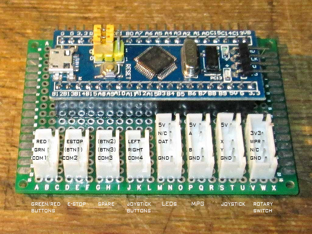
i can also share my YIO modules firmware which use STM32F030 MCUs. it's a really simple serial protocol on RS-485 half-duplex bus @5Mbps. if you're willing to make your own interface hardware - it is surely doable, no problem
those MM64 connectors are documented in the manual. i believe 64ins/64outs on the base I/O card should be present on the RIO1 bus.
Please Log in or Create an account to join the conversation.
- MulBe039
- Offline
- New Member
-
- Posts: 13
- Thank you received: 4
In position control mode the commanded resolution is 23,040,000 cpr regardless of what kind of encoder is used.
Is this a limitation imposed by linuxCNC or the Mitsubishi Drives?
when the spindle is used as a C-axis they usually use a really high resolution encoder. also, the controller explicitly signals the spindle drive that it is currently in C-axis mode. i believe to set PID gains which match other axes to achieve better synchronicity.
This sounds to me like it would only be a matter of putting a spider into the spindlebore with an appropriate encoder, and initiating the drives with different parameters when they are starting up.
Plus as I said, maybe some kind of hydraulic break which holds the spindle in place if it reaches the desired position.
I probably wouldn't use this for synchronized motion between the A axis and other axies, all the operations would be:
rotate A by X degrees--> lock spindle-->machine feature--> unlock spindle --> rotate ....
yeah, the common practice to use generic 24V I/O modules is kinda wasteful price-wise. with all those input optocouplers and protected driver ICs. i wanted to come up with something more optimal, but it hasn't happen so far.
Hence why I wanted to simply step-down the supply voltage and perhaps go with the 7i42TA i found on sale.
Maybe I wasn't entirely clear on this part: I would only drop the supplyvoltage for all the buttons in the console, so that I can directly hook them up to a board without the risk of frying it.
The sensors will remain at 24V
i did a control panel controller a while ago using a $2 STM32 controller [...] i can share the code and configs, but they are not documented apart from some comments in the code...
I wasn't sure if this was something that is possible. If this is feasible at my current skilllevel, I will probably end up doing this at some point for sure. If I understand correctly, it has the big advantage of being infinitely flexible if I ever want to add any functionality/buttons to my panel/machine.
What I really need to know is how the communication between the MCU and linuxcnc is done, and how you set up linuxcnc to have individual responses to certain events from the MCU. From a brief search in the wiki it seems that this can be done via HIDcomp and/or halui if I figure out how to get an MCU to act as an USB device. (there should be plenty of tutorials available online to do just that)
Is this what you have done here?
If so please do post your code and config, it will certainly help to have a working example that works on a recent-ish version of linuxcnc.
If not, could you still post the code, and I will have a look at it and see if I can figure out what you have done.
i can also share my YIO modules firmware which use STM32F030 MCUs. it's a really simple serial protocol on RS-485 half-duplex bus @5Mbps. if you're willing to make your own interface hardware - it is surely doable, no problem
Not sure what you mean by this?
Are you suggesting I build your YIO modules myself?
Or that I use that firmware to build a 'clone' for the baseIo & RemoteI/O boards?
those MM64 connectors are documented in the manual. i believe 64ins/64outs on the base I/O card should be present on the RIO1 bus.
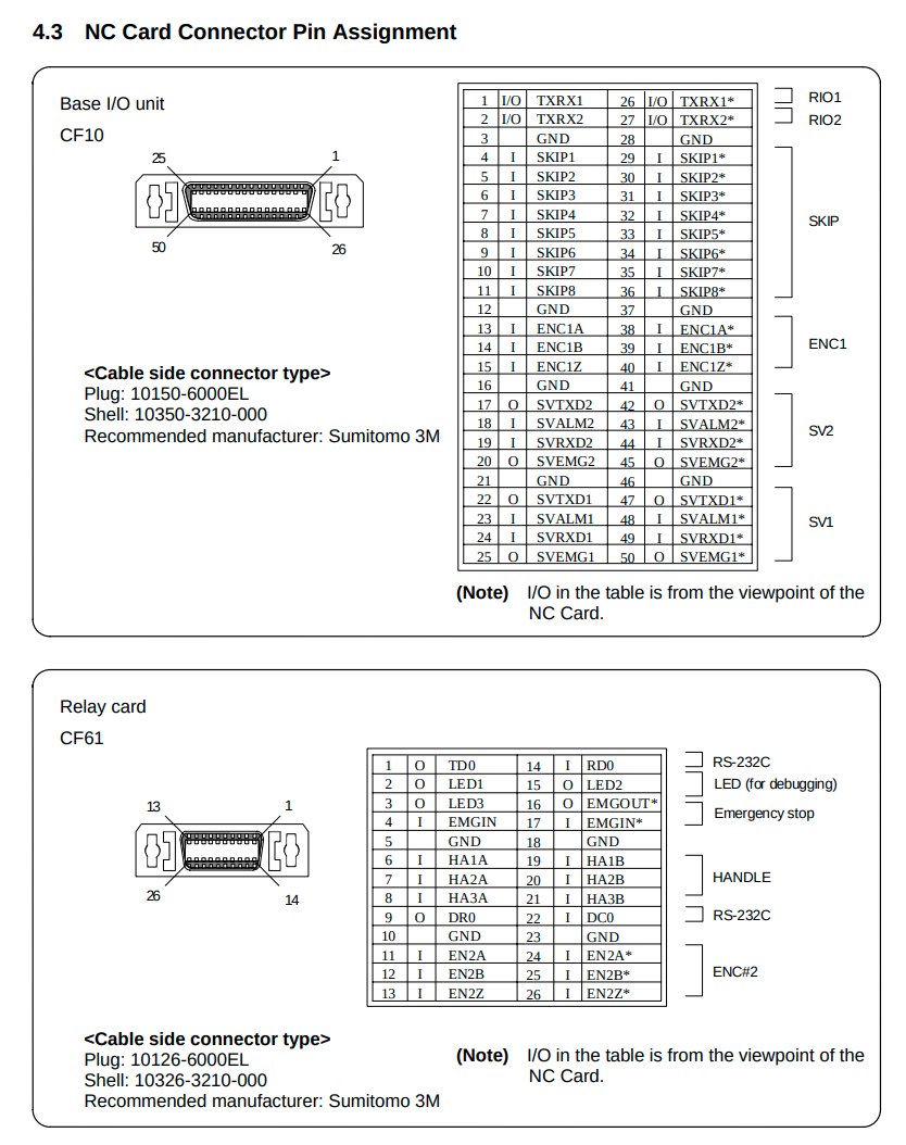
Have a look at page 14 of the electronics manual I uploaded. II'm not sure how cf31-34 are supposed to be adressed trough that cf10 connection, but if I see this correclty, we could ignore most of the pins, as they are already being handled trough the sh21 port on your card.
As I said, if you really think we can make this work with your card, we can also try that. But if we do, that will have to happen under your direction. I've never reversed engineered anything like this before, and I think it might be outside of the scope of things that I am capable of, without outside help.
However, I suggest we only do this if you actually WANT to do that. I am aware that I am basically a stranger who came onto this forum asking for free help with a problem. I don't want anyone doing work which he doesn't want to do, just because that was the more convenient solution for me.
But if we can give back to the community and somehow help others in the future who might run into a similar problem, I will gladly do my part to make that happen.
P.S. I know i've probably already asked a few questions here that are already answered in the wiki. I will familiarize myself with that as soon as possible, I have a few things coming up in the next weeks that will take up the majority of my time and I really needed to have a rough idea of the size of this project before that so that I know how long my machine is going to be non-operational once I start working on this.
Once I know that, I will probably be much less active until 19th of january, at which point I can dedicate most of my time to this project for a few weeks.
Please Log in or Create an account to join the conversation.
- dm17ry
-
- Offline
- Elite Member
-
- Posts: 203
- Thank you received: 88
it's the spindle drive and its control protocol.
Is this a limitation imposed by linuxCNC or the Mitsubishi Drives?In position control mode the commanded resolution is 23,040,000 cpr regardless of what kind of encoder is used.
does the lathe has a spindle encoder connected to the spindle drive? in addition to the PLG on the spindle motor...I probably wouldn't use this for synchronized motion between the A axis and other axies, all the operations would be:
rotate A by X degrees--> lock spindle-->machine feature--> unlock spindle --> rotate ....
kinda. the MCU presents itself as a composite USB HID device. it emulates a normal PC keyboard, a wheel mouse (with joystick and MPG) and a few more buttons. linuxcnc gets them using the hidcomp. i wanted to have an ability to use the alphanumeric membrane keyboard anywhere including BIOS SETUP. is the goal is only a few buttons - i think it will be easier to implement a custom HID device and a userspace linuxcnc component which will poll it for keypresses...Is this what you have done here? If so please do post your code and config, it will certainly help to have a working example that works on a recent-ish version of linuxcnc.
If not, could you still post the code, and I will have a look at it and see if I can figure out what you have done.
i will publish the code to the github in a few days after a bit of cleanup
if you want more I/O points than available on the card you'll need some way to bring them to the PC. the parallel port is kinda limited. adding another PCI/ethernet card may bring some compatibility issues. there's a serial YIO protocol already present in the firmware which supports up to 256 I/O points at 0.88ms poll cycle. so yes, i think you can use a $2 MCU to talk to the card and any I/O interfaces you like. with shift registers as you suggested, or whatever...Not sure what you mean by this?
Are you suggesting I build your YIO modules myself?
Or that I use that firmware to build a 'clone' for the baseIo & RemoteI/O boards?
not really. my card only implements the "SV1" part of the CF10 connectorHave a look at page 14 of the electronics manual I uploaded. II'm not sure how cf31-34 are supposed to be adressed trough that cf10 connection, but if I see this correclty, we could ignore most of the pins, as they are already being handled trough the sh21 port on your card.
i'd like to implement it, because i think it will save a lot of rewiring and keep the possibility to instantly fall back to the original control for whatever reason... but need to evaluate how much time it will take. recently i've got a retrofit candidate with similar base I/O and RIO. will do some tests in week or two and decide if it's feasible.However, I suggest we only do this if you actually WANT to do that. I am aware that I am basically a stranger who came onto this forum asking for free help with a problem. I don't want anyone doing work which he doesn't want to do, just because that was the more convenient solution for me.
Please Log in or Create an account to join the conversation.
- MulBe039
- Offline
- New Member
-
- Posts: 13
- Thank you received: 4
does the lathe has a spindle encoder connected to the spindle drive? in addition to the PLG on the spindle motor...
not that I am aware of, but that should be something that is doable. Anyways- it is a project for another day. I was just wondering if the drives natively supported those kinds of shenanigans.
i will publish the code to the github in a few days after a bit of cleanup
Okay thank you very much for that
if you want more I/O points than available on the card you'll need some way to bring them to the PC. the parallel port is kinda limited. adding another PCI/ethernet card may bring some compatibility issues. there's a serial YIO protocol already present in the firmware which supports up to 256 I/O points at 0.88ms poll cycle. so yes, i think you can use a $2 MCU to talk to the card and any I/O interfaces you like. with shift registers as you suggested, or whatever...
Okay that sounds indeed like something that I should try once the card arrives. Am I correct in assuming that any board which can be programmed in C and is capable of half-duplex RS-485 should work with your firmware with perhaps a few minor mods, or should I stick to stm32 architecture? I'm asking because I have a whole bunch of esp32 and STM32F103C8T6 boards lying around.
not really. my card only implements the "SV1" part of the CF10 connector
yeah but sv2 isn't hooked up, the encoders are reached trough to linuxcnc by your board directly from the drives if I understand correctly, RIO2 isn't hooked up, and the way I see it, RIO1 is reached trough directly to the RIO Board.
i'd like to implement it, because i think it will save a lot of rewiring and keep the possibility to instantly fall back to the original control for whatever reason... but need to evaluate how much time it will take. recently i've got a retrofit candidate with similar base I/O and RIO. will do some tests in week or two and decide if it's feasible.
That is of course true- I also wanted to try and work around irreversible changes as much as possible. Hence why I liked the idea of the HID controller so much- simply building a new console that I can put in front of the old one. Arguably not very elegant, but at least reversible should I ever have the need to do so.
Please Log in or Create an account to join the conversation.
- MulBe039
- Offline
- New Member
-
- Posts: 13
- Thank you received: 4
Here is a complete Backup of the Drive mounted in the Control PC of the Ecoca El-4610-E.
The control, as mentioned is a Mitsubishi Meldasmagic64.
The PC is an IPC of the Type MWS-842 and was running Windows NT 4.0 on Servicepack 5 build 1381
The Backup was made, and can be accessed with the freeware version of AOMEI Backupper. Simply use the explore Backup tool to mount the partitions.
What might be of interest to tommylight and others working on Meldasmagic64 controls, is that the drive contains all the software necessary to communicate and backup the NC Card. A rudamentary internet search showed that tools like magictrs.exe etc are not easy to come by.
I also found the PARAMET.bin file which I assume to be a backup of the paramters stored on the card and what I assume to be the ladder file USERPLC.LAD - haven't had any success in properly opening/editing/reading/porting this. Any approaches/references to useful software is appreciated.
These two files, since they are the most relevant for such a retrofit as this one, are already exracted from the drive image and were uploaded separately.
Everything can be found here:
drive.google.com/drive/folders/1ENcGRNDR...d5pFOblP?usp=sharing
Please Log in or Create an account to join the conversation.