

- Posts: 189
- Thank you received: 44
Bridgeport Torq-Cut TC4G Retrofit
5 years 8 months ago #198813
by chopper79
Replied by chopper79 on topic Bridgeport Torq-Cut TC4G Retrofit
Thinking about this a bit more and looking over the prints for the machine. (Posted on a previous post on this thread)
The original wiring used the following:
* +/-10vdc = Pin 3 VFD
* 0vdc = Pin 4 VFD
* Spindle enable (FWD) = Pin 37 on VFD
There was never a REV pin used on the original wiring.
So should I do the following:?
* 24+vdc to ENA+
* ENA - to Pin 37 on VFD
* Leave analog pin 3 and pin 4 alone (keep them on the pins they are at and the analog5 output on 7i77)
This would mimic the factory wiring for the VFD. Spindle FWD will come on when I press the FWD button in the gui or M3, but not sure what I would get when REV button on gui and M4 would produce. Guess the analog voltage will flip its sign and allow REV to happen.
I will go through PNCconf again to see what it produces as far as a setup goes.
The original wiring used the following:
* +/-10vdc = Pin 3 VFD
* 0vdc = Pin 4 VFD
* Spindle enable (FWD) = Pin 37 on VFD
There was never a REV pin used on the original wiring.
So should I do the following:?
* 24+vdc to ENA+
* ENA - to Pin 37 on VFD
* Leave analog pin 3 and pin 4 alone (keep them on the pins they are at and the analog5 output on 7i77)
This would mimic the factory wiring for the VFD. Spindle FWD will come on when I press the FWD button in the gui or M3, but not sure what I would get when REV button on gui and M4 would produce. Guess the analog voltage will flip its sign and allow REV to happen.
I will go through PNCconf again to see what it produces as far as a setup goes.
Please Log in or Create an account to join the conversation.
- tommylight
-

- Offline
- Moderator
-

5 years 8 months ago #198816
by tommylight
Replied by tommylight on topic Bridgeport Torq-Cut TC4G Retrofit
+-10V and ena from the 7i77 should be all that is required for such a drive.
Since last i used the Elumatec was some 8 months ago i do remember much more about this than what and how it was on the Hurco, so for sure i know that the spindle will spin at 1RPM whenever the fwd or rev is pressed on the GUI, and yes it does spin CV in BOTH cases until the speed is raised at which point the spindle reverses at the speed set for CCV.
Unfortunately i do not recall much about the Hurco, but i am sure it did not need the enable from LinuxCNC to orient, the drive did that on it's own and would set a pin high when it was oriented.
Did you check that on your drive ?
Since last i used the Elumatec was some 8 months ago i do remember much more about this than what and how it was on the Hurco, so for sure i know that the spindle will spin at 1RPM whenever the fwd or rev is pressed on the GUI, and yes it does spin CV in BOTH cases until the speed is raised at which point the spindle reverses at the speed set for CCV.
Unfortunately i do not recall much about the Hurco, but i am sure it did not need the enable from LinuxCNC to orient, the drive did that on it's own and would set a pin high when it was oriented.
Did you check that on your drive ?
Please Log in or Create an account to join the conversation.
5 years 8 months ago - 5 years 8 months ago #198833
by chopper79
Replied by chopper79 on topic Bridgeport Torq-Cut TC4G Retrofit
Well here is where I am at right now:
* 24+vdc to ena5 +
* Ena5 - to FWD on VFD (pin37) (Same way factory had it)
* Analog5 outputs to the respective pins on VFD
When I press CW or CCW on the gui the spindle rotates 1rpm in the correct directions. When I command M3s100 or M4s100 the spindle rotates correctly based on the command given.
Besides the 1 rpm rotation this is all functioning correctly. This may not be able to be corrected and/or bother anything.
***** Orientation of the spindle for ATC *****
Factory wiring had no wire for orientation or orientation complete. This seemed to be done by original controller using the spindle encoder and not the motor encoder. The orientation command was given for ATC and the spindle would rotate to 90.66° from the index mark and hold.
I can not get the spindle to orient unless I use the following: (I turned this feature on)
* Orient pin on VFD
* FWD pin on VFD
When using these the spindle will orient and provide a orient complete signal. If the VFD is in FWD mode then the orient pin can be excited and the VFD will orient the spindle to the XXXX pulses from index mark using the motor encoder. With FWD being on the enable I can now use the orient input to trigger the orient process.
Seem this is ok
* 24+vdc to ena5 +
* Ena5 - to FWD on VFD (pin37) (Same way factory had it)
* Analog5 outputs to the respective pins on VFD
When I press CW or CCW on the gui the spindle rotates 1rpm in the correct directions. When I command M3s100 or M4s100 the spindle rotates correctly based on the command given.
Besides the 1 rpm rotation this is all functioning correctly. This may not be able to be corrected and/or bother anything.
***** Orientation of the spindle for ATC *****
Factory wiring had no wire for orientation or orientation complete. This seemed to be done by original controller using the spindle encoder and not the motor encoder. The orientation command was given for ATC and the spindle would rotate to 90.66° from the index mark and hold.
I can not get the spindle to orient unless I use the following: (I turned this feature on)
* Orient pin on VFD
* FWD pin on VFD
When using these the spindle will orient and provide a orient complete signal. If the VFD is in FWD mode then the orient pin can be excited and the VFD will orient the spindle to the XXXX pulses from index mark using the motor encoder. With FWD being on the enable I can now use the orient input to trigger the orient process.
Seem this is ok
Last edit: 5 years 8 months ago by chopper79.
Please Log in or Create an account to join the conversation.
5 years 8 months ago - 5 years 8 months ago #198844
by chopper79
Replied by chopper79 on topic Bridgeport Torq-Cut TC4G Retrofit
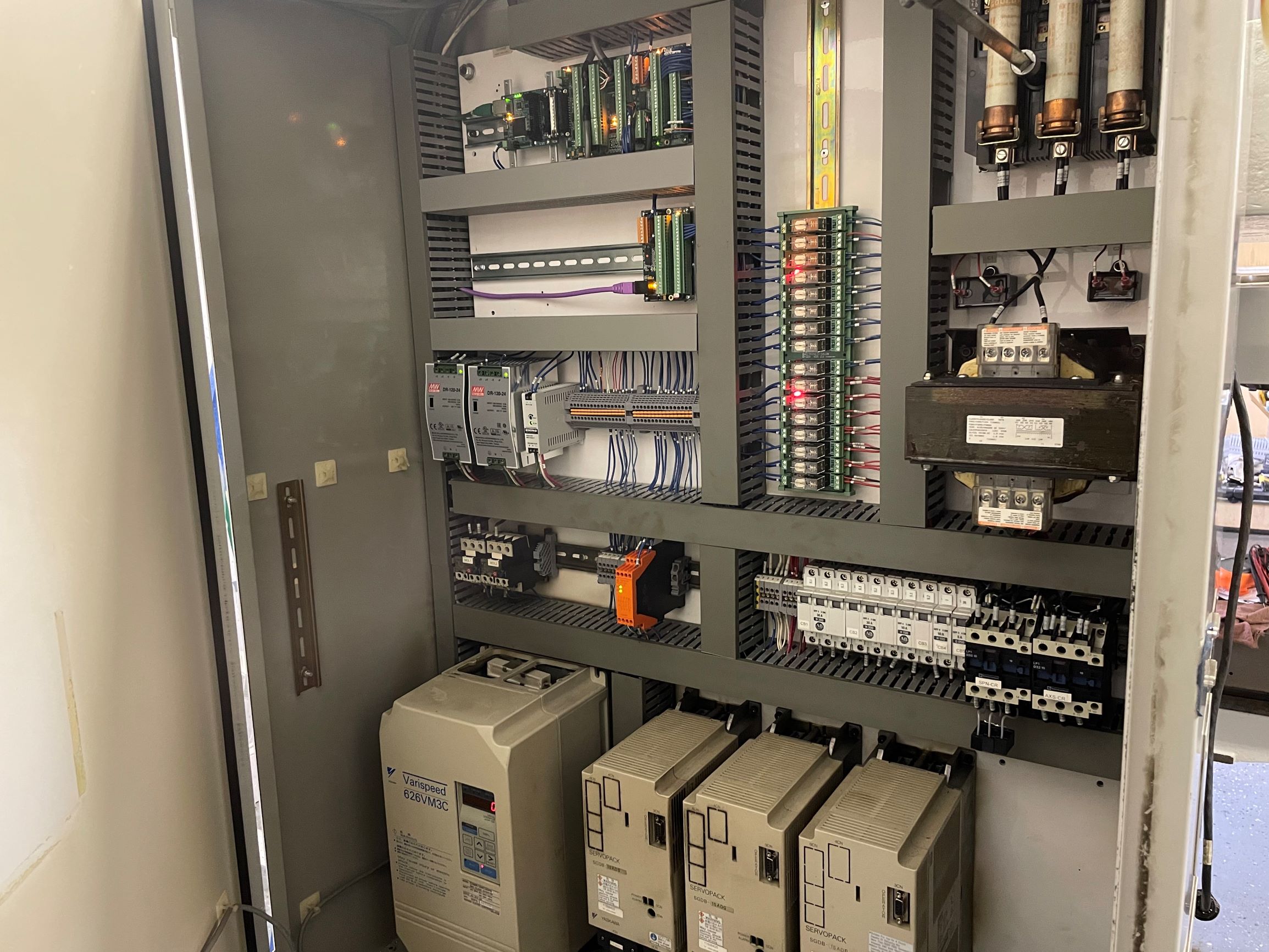
Need to clean a few things up and little more wire management, but all in all the cabinet is almost completed.
Last edit: 5 years 8 months ago by chopper79.
The following user(s) said Thank You: arvidb, tommylight
Please Log in or Create an account to join the conversation.
5 years 8 months ago - 5 years 8 months ago #199007
by chopper79
Replied by chopper79 on topic Bridgeport Torq-Cut TC4G Retrofit
Had a little bit of time today to work on the configuration.
* Z axis brake is completed
* Way lube is completed (Using classic ladder)
* Way lube lines are all purged and oil reaches each point needed
* Light beacon is completed (Green, yellow, and red)
Green is solid during program run, Green flashes during program pause, Yellow is on when machine is on and program is not running, and Red is on when Estop is on
New proximity sensors show up tomorrow so I will be able to get those in and then begin the ATC configuration. Will update as I progress further.
* Z axis brake is completed
* Way lube is completed (Using classic ladder)
* Way lube lines are all purged and oil reaches each point needed
* Light beacon is completed (Green, yellow, and red)
Green is solid during program run, Green flashes during program pause, Yellow is on when machine is on and program is not running, and Red is on when Estop is on
New proximity sensors show up tomorrow so I will be able to get those in and then begin the ATC configuration. Will update as I progress further.
Last edit: 5 years 8 months ago by chopper79.
Please Log in or Create an account to join the conversation.
5 years 8 months ago - 5 years 8 months ago #199204
by chopper79
Replied by chopper79 on topic Bridgeport Torq-Cut TC4G Retrofit
Quick question
Working on the tool changer a bit and I am using a subroutine to perform this (Used toolchange.ngc as a template and modifying as needed)
The question I have is do I need to use the carousel.comp when using this so the carousel can find tool #1 via the proximity sensor and also manage the rotation and tool count?
Thinking it should be used as the toolchange.ngc does not seem to manage CW and CCW rotation and to know what the current pocket is, etc. I may be wrong but so far I do not see it in the .ngc code.
**** Little more thinking on this and I may go ahead and use the carousel.comp and then use the .ngc file to set the digital outs for the HAL pins. Thinking that this will allow all the functionality of the carousel.comp and keep the subroutine compact and easy to follow. ****
I will give it a try to see what happens in the next few days. My proximity sensors are being held up in shipping due to the winter storms.
Thank you
Working on the tool changer a bit and I am using a subroutine to perform this (Used toolchange.ngc as a template and modifying as needed)
The question I have is do I need to use the carousel.comp when using this so the carousel can find tool #1 via the proximity sensor and also manage the rotation and tool count?
Thinking it should be used as the toolchange.ngc does not seem to manage CW and CCW rotation and to know what the current pocket is, etc. I may be wrong but so far I do not see it in the .ngc code.
**** Little more thinking on this and I may go ahead and use the carousel.comp and then use the .ngc file to set the digital outs for the HAL pins. Thinking that this will allow all the functionality of the carousel.comp and keep the subroutine compact and easy to follow. ****
I will give it a try to see what happens in the next few days. My proximity sensors are being held up in shipping due to the winter storms.
Thank you
Last edit: 5 years 8 months ago by chopper79.
Please Log in or Create an account to join the conversation.
Time to create page: 0.081 seconds