Bridgeport Torq-Cut TC4G Retrofit
- chopper79
-
 Topic Author
- Offline
- Elite Member
-

Less
More
- Posts: 193
- Thank you received: 44
13 Feb 2021 23:44 - 13 Feb 2021 23:50 #198753
by chopper79
Replied by chopper79 on topic Bridgeport Torq-Cut TC4G Retrofit
I was thinking that when you click the CW or CCW on axis gui that there was no output at all. I did contact the new owner of the Matsurra I did a retrofit on a couple years ago and when they click either of those the spindle does not turn at all. I click them and you get an output of ~ 0.006vdc on the analog5 output and the spindle rotates ~1rpm.
From what I have found is that it has always been like this and I guess the past retrofits just did not care about the (in my case) 0.006vdc output so I never noticed it.
I did try an old hard drive I had from 3 years ago that had an old build of LCNC on it. The CW and CCW do the exact same thing as the new version. Like I said I guess I just never noticed it is all.
As far as the M19 goes... that was my misunderstanding as I never used M19 on my older machines with ATC. I always used the output of CL to exercise the orientation input on the VFD. Found that out after reviewing my old configurations and have not updated the thread accordingly. So I will take that egg on my face for that one.
On another note... getting further along on the configuration. Working out the way lube bugs now and then will begin with the ATC after I order some new prox sensors. The current ones or NPN and the 7i77 does not work with them unless I use a pull up. So I will just purchase (4) new sensors that are PNP and be good to go on moving forward with ATC.
Still owe y'all some pictures of the electrical cabinet. I will do that this weekend.
Appreciate everyone's input so far.
Last edit: 13 Feb 2021 23:50 by chopper79.
Please Log in or Create an account to join the conversation.
- tommylight
-

- Away
- Moderator
-

Less
More
- Posts: 21632
- Thank you received: 7387
14 Feb 2021 00:22 #198765
by tommylight
Replied by tommylight on topic Bridgeport Torq-Cut TC4G Retrofit
Read this several times by now, so here is what i think as i can not confirm any of it:
Is there an encoder on the spindle?
Is that encoder set properly and checked using halshow to make sure 1 rotation is actual 1 rotation?
On one of the retrofits i had everything set and wired and configured in hal, it would do the same thing, namely run at a very low speed when clicking forward or reverse. It was not used for anything in hal, the speed was always spot on so i did not bother with it, it is still in use every day.
The other one had roughly the same setup but the spindle feedback went to the drive and from there to Mesa boards, drive had it's own Orient logic and sensors and everything, was quite a while back so i am foggy, never used buttons but i do not recall it ever spinning without telling it the speed in gcode.
The above is not of any help, but i am out of ideas for now.
What pin is controlling the spindle, spindle-on or spindle-cv/spindle-ccv?
Is the drive 0-10V or +-10V ?
The following user(s) said Thank You: chopper79
Please Log in or Create an account to join the conversation.
- chopper79
-
Topic Author
- Offline
- Elite Member
-
Less
More
- Posts: 193
- Thank you received: 44
14 Feb 2021 00:33 #198767
by chopper79
1) Yes there is an encoder on the spindle and is used only for feedback to LCNC
2) The spindle motor has its own encoder in the motor and is only for the spindle drive
3) Yes, 1rotation is 1 rotation
4) Spindle is +-10v
5) Using analog5 for output
6) Pin 1 and Pin 2 on 7i77 out to VFD which are used for CW and CCW (FWD and REV) using spindle.0.forward and spindle.0.reverse in HAL
7) Orientation for ATC is handled by the drive itself and not LCNC
The M19 orientation question I had was a misunderstanding on my end. (Lets disregard that question and discussion for now..haha)
Replied by chopper79 on topic Bridgeport Torq-Cut TC4G Retrofit
Read this several times by now, so here is what i think as i can not confirm any of it:
Is there an encoder on the spindle?
Is that encoder set properly and checked using halshow to make sure 1 rotation is actual 1 rotation?
On one of the retrofits i had everything set and wired and configured in hal, it would do the same thing, namely run at a very low speed when clicking forward or reverse. It was not used for anything in hal, the speed was always spot on so i did not bother with it, it is still in use every day.
The other one had roughly the same setup but the spindle feedback went to the drive and from there to Mesa boards, drive had it's own Orient logic and sensors and everything, was quite a while back so i am foggy, never used buttons but i do not recall it ever spinning without telling it the speed in gcode.
The above is not of any help, but i am out of ideas for now.
What pin is controlling the spindle, spindle-on or spindle-cv/spindle-ccv?
Is the drive 0-10V or +-10V ?
1) Yes there is an encoder on the spindle and is used only for feedback to LCNC
2) The spindle motor has its own encoder in the motor and is only for the spindle drive
3) Yes, 1rotation is 1 rotation
4) Spindle is +-10v
5) Using analog5 for output
6) Pin 1 and Pin 2 on 7i77 out to VFD which are used for CW and CCW (FWD and REV) using spindle.0.forward and spindle.0.reverse in HAL
7) Orientation for ATC is handled by the drive itself and not LCNC
The M19 orientation question I had was a misunderstanding on my end. (Lets disregard that question and discussion for now..haha)
Please Log in or Create an account to join the conversation.
- tommylight
-
- Away
- Moderator
-
Less
More
- Posts: 21632
- Thank you received: 7387
14 Feb 2021 11:31 #198789
by tommylight
Replied by tommylight on topic Bridgeport Torq-Cut TC4G Retrofit
4 and 6 are redundant in this case as +-10V should be controled by spindle-enable.
7i77 has the spindle enable separate from other enables, so try using that and leave the fwd/rew to be controled by +-10V.
7i77 has the spindle enable separate from other enables, so try using that and leave the fwd/rew to be controled by +-10V.
The following user(s) said Thank You: chopper79
Please Log in or Create an account to join the conversation.
- chopper79
-
Topic Author
- Offline
- Elite Member
-
Less
More
- Posts: 193
- Thank you received: 44
14 Feb 2021 14:29 #198807
by chopper79
I will double check the spindle being 0-10v or +-10v in a few. I may have incorrectly answered that one as I was tied up with a few things right at that moment and did not give it the full attention it deserved.
Replied by chopper79 on topic Bridgeport Torq-Cut TC4G Retrofit
4 and 6 are redundant in this case as +-10V should be controled by spindle-enable.
7i77 has the spindle enable separate from other enables, so try using that and leave the fwd/rew to be controled by +-10V.
I will double check the spindle being 0-10v or +-10v in a few. I may have incorrectly answered that one as I was tied up with a few things right at that moment and did not give it the full attention it deserved.
Please Log in or Create an account to join the conversation.
- chopper79
-
Topic Author
- Offline
- Elite Member
-
Less
More
- Posts: 193
- Thank you received: 44
14 Feb 2021 14:42 - 14 Feb 2021 14:47 #198809
by chopper79
Replied by chopper79 on topic Bridgeport Torq-Cut TC4G Retrofit
Ok, just checked on this real quick and here are the pins used on the VFD
Pin 3 = +/-10vdc
Pin 4 = 0vdc
When you mention the 7i77 has its own enable is that what you are suggesting I connect my wiring to for speed control or are you suggesting a HAL connection to something? I am figuring it is a HAL connection as enable on the 7i77 will just short out as it is a closure I thought.
Currently I have the enable lines connected to the enable circuit of the VFD. Then the analog5 out to Pins 3,4 on VFD. Attached is a snippet of the manual that shows the function of Pin 3 for +-10vdc. The VFD still requires a FWD or REV signal it seems to function.
Last edit: 14 Feb 2021 14:47 by chopper79.
Please Log in or Create an account to join the conversation.
- chopper79
-
Topic Author
- Offline
- Elite Member
-
Less
More
- Posts: 193
- Thank you received: 44
14 Feb 2021 16:39 #198813
by chopper79
Replied by chopper79 on topic Bridgeport Torq-Cut TC4G Retrofit
Thinking about this a bit more and looking over the prints for the machine. (Posted on a previous post on this thread)
The original wiring used the following:
* +/-10vdc = Pin 3 VFD
* 0vdc = Pin 4 VFD
* Spindle enable (FWD) = Pin 37 on VFD
There was never a REV pin used on the original wiring.
So should I do the following:?
* 24+vdc to ENA+
* ENA - to Pin 37 on VFD
* Leave analog pin 3 and pin 4 alone (keep them on the pins they are at and the analog5 output on 7i77)
This would mimic the factory wiring for the VFD. Spindle FWD will come on when I press the FWD button in the gui or M3, but not sure what I would get when REV button on gui and M4 would produce. Guess the analog voltage will flip its sign and allow REV to happen.
I will go through PNCconf again to see what it produces as far as a setup goes.
Please Log in or Create an account to join the conversation.
- tommylight
-
- Away
- Moderator
-
Less
More
- Posts: 21632
- Thank you received: 7387
14 Feb 2021 17:41 #198816
by tommylight
Replied by tommylight on topic Bridgeport Torq-Cut TC4G Retrofit
+-10V and ena from the 7i77 should be all that is required for such a drive.
Since last i used the Elumatec was some 8 months ago i do remember much more about this than what and how it was on the Hurco, so for sure i know that the spindle will spin at 1RPM whenever the fwd or rev is pressed on the GUI, and yes it does spin CV in BOTH cases until the speed is raised at which point the spindle reverses at the speed set for CCV.
Unfortunately i do not recall much about the Hurco, but i am sure it did not need the enable from LinuxCNC to orient, the drive did that on it's own and would set a pin high when it was oriented.
Did you check that on your drive ?
Please Log in or Create an account to join the conversation.
- chopper79
-
Topic Author
- Offline
- Elite Member
-
Less
More
- Posts: 193
- Thank you received: 44
14 Feb 2021 19:45 - 14 Feb 2021 20:39 #198833
by chopper79
Replied by chopper79 on topic Bridgeport Torq-Cut TC4G Retrofit
Well here is where I am at right now:
* 24+vdc to ena5 +
* Ena5 - to FWD on VFD (pin37) (Same way factory had it)
* Analog5 outputs to the respective pins on VFD
When I press CW or CCW on the gui the spindle rotates 1rpm in the correct directions. When I command M3s100 or M4s100 the spindle rotates correctly based on the command given.
Besides the 1 rpm rotation this is all functioning correctly. This may not be able to be corrected and/or bother anything.
***** Orientation of the spindle for ATC *****
Factory wiring had no wire for orientation or orientation complete. This seemed to be done by original controller using the spindle encoder and not the motor encoder. The orientation command was given for ATC and the spindle would rotate to 90.66° from the index mark and hold.
I can not get the spindle to orient unless I use the following: (I turned this feature on)
* Orient pin on VFD
* FWD pin on VFD
When using these the spindle will orient and provide a orient complete signal. If the VFD is in FWD mode then the orient pin can be excited and the VFD will orient the spindle to the XXXX pulses from index mark using the motor encoder. With FWD being on the enable I can now use the orient input to trigger the orient process.
Seem this is ok
Last edit: 14 Feb 2021 20:39 by chopper79.
Please Log in or Create an account to join the conversation.
- chopper79
-
Topic Author
- Offline
- Elite Member
-
Less
More
- Posts: 193
- Thank you received: 44
14 Feb 2021 21:23 - 14 Feb 2021 21:23 #198844
by chopper79
Replied by chopper79 on topic Bridgeport Torq-Cut TC4G Retrofit
Need to clean a few things up and little more wire management, but all in all the cabinet is almost completed.
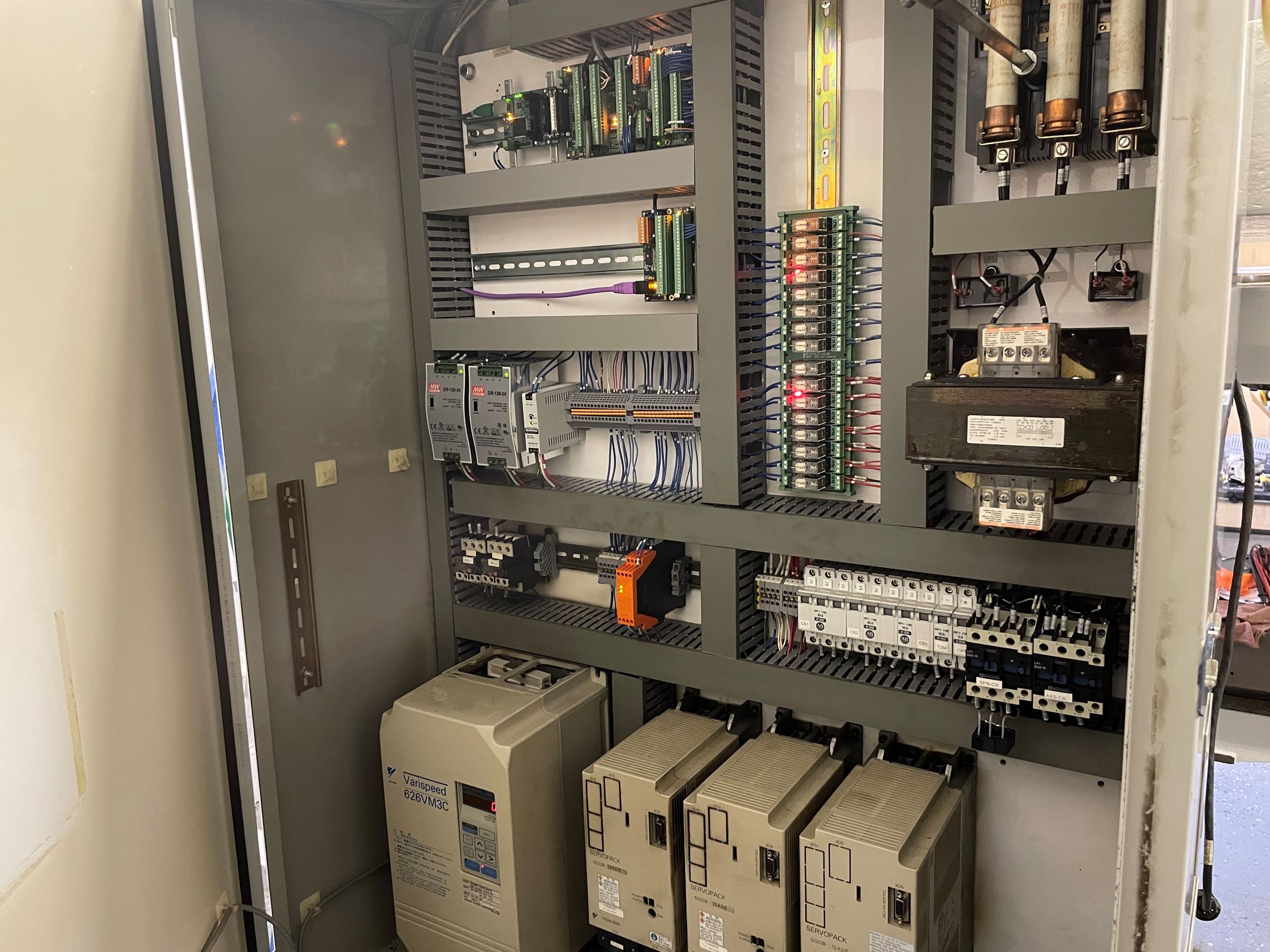
Attachments:
Last edit: 14 Feb 2021 21:23 by chopper79.
The following user(s) said Thank You: arvidb, tommylight
Please Log in or Create an account to join the conversation.
Time to create page: 0.230 seconds