One more HURCO BMC 20P Retrofit
- tommylight
-

- Offline
- Moderator
-

Less
More
- Posts: 21625
- Thank you received: 7383
13 Jun 2022 00:18 #245038
by tommylight
Replied by tommylight on topic One more HURCO BMC 20P Retrofit
Pretty sure you can not e-mail that size.
I meant google sharing.
I meant google sharing.
Please Log in or Create an account to join the conversation.
- smc.collins
- Offline
- Platinum Member
-

Less
More
- Posts: 723
- Thank you received: 139
13 Jun 2022 01:01 #245044
by smc.collins
Replied by smc.collins on topic One more HURCO BMC 20P Retrofit
I shared my complete schematics for my cincinatti using google mydrive
Please Log in or Create an account to join the conversation.
- christos
- Offline
- New Member
-

Less
More
- Posts: 15
- Thank you received: 3
16 Aug 2022 09:00 #249868
by christos
Replied by christos on topic One more HURCO BMC 20P Retrofit
After several months of running around with other issues, I think I managed to get them right this time.
Below is a link from google drive
drive.google.com/file/d/12FVenEbqzGOXnxs...kOC/view?usp=sharing
Please let me know if it is working for you as well.
Below is a link from google drive
drive.google.com/file/d/12FVenEbqzGOXnxs...kOC/view?usp=sharing
Please let me know if it is working for you as well.
The following user(s) said Thank You: tommylight, smc.collins
Please Log in or Create an account to join the conversation.
- smc.collins
- Offline
- Platinum Member
-
Less
More
- Posts: 723
- Thank you received: 139
16 Aug 2022 11:02 #249880
by smc.collins
Replied by smc.collins on topic One more HURCO BMC 20P Retrofit
awesome thank you
Please Log in or Create an account to join the conversation.
- christos
- Offline
- New Member
-
Less
More
- Posts: 15
- Thank you received: 3
20 Aug 2022 20:19 - 20 Aug 2022 20:26 #250122
by christos
Replied by christos on topic One more HURCO BMC 20P Retrofit
Hello Guys,
Quick queries regarding cabling on the 7i77...
I’m trying to connect the cables coming from the Yaskawa servopack regarding the encoder to the 7i77.
For instance I’m trying to connect (how is written in the diagrams), what is coming from 1CN connector, Phase A /Phase A-, Phase B /Phase B-, Marker / Marker -, to the “TB3, Encoder 2” pins in the 7i77. I have seen from the manual of the 7i77 that it accepts QA0, /QA0, QB0, /QB0, IDX0 and /IDXO.
Are the below connections correct? (Does it really matter to get the A/B letters accordingly?)
“Phase A ” to “QA0”
“Phase A-” to “/QA0”
“Phase B ” to “QB0”
“Phase B-” to “/QB0”
“Marker ” to “IDX0”
“Marker -” to “/IDX0”
By the way, my card is the “sinking output version” 7i77D (I will gather different queries for that in the future) and on the Yaskawa manual, the symbols are “PAO, *PAO, PBO,*PBO, PCO, *PCO).
Do I have to ground these connections back from the 7i77 to the yaskawa servopack?
I hope to repeat the same process on all drives (including the spindle).
Also a special query for tommylight: Could you remember if you used new PSUs for the 5/12/24V or did you use the one that is already inside the cabinet (left top side)?
Last but not least, a rough photo of how the setup is right now (the wooden back is just till setup is finished)
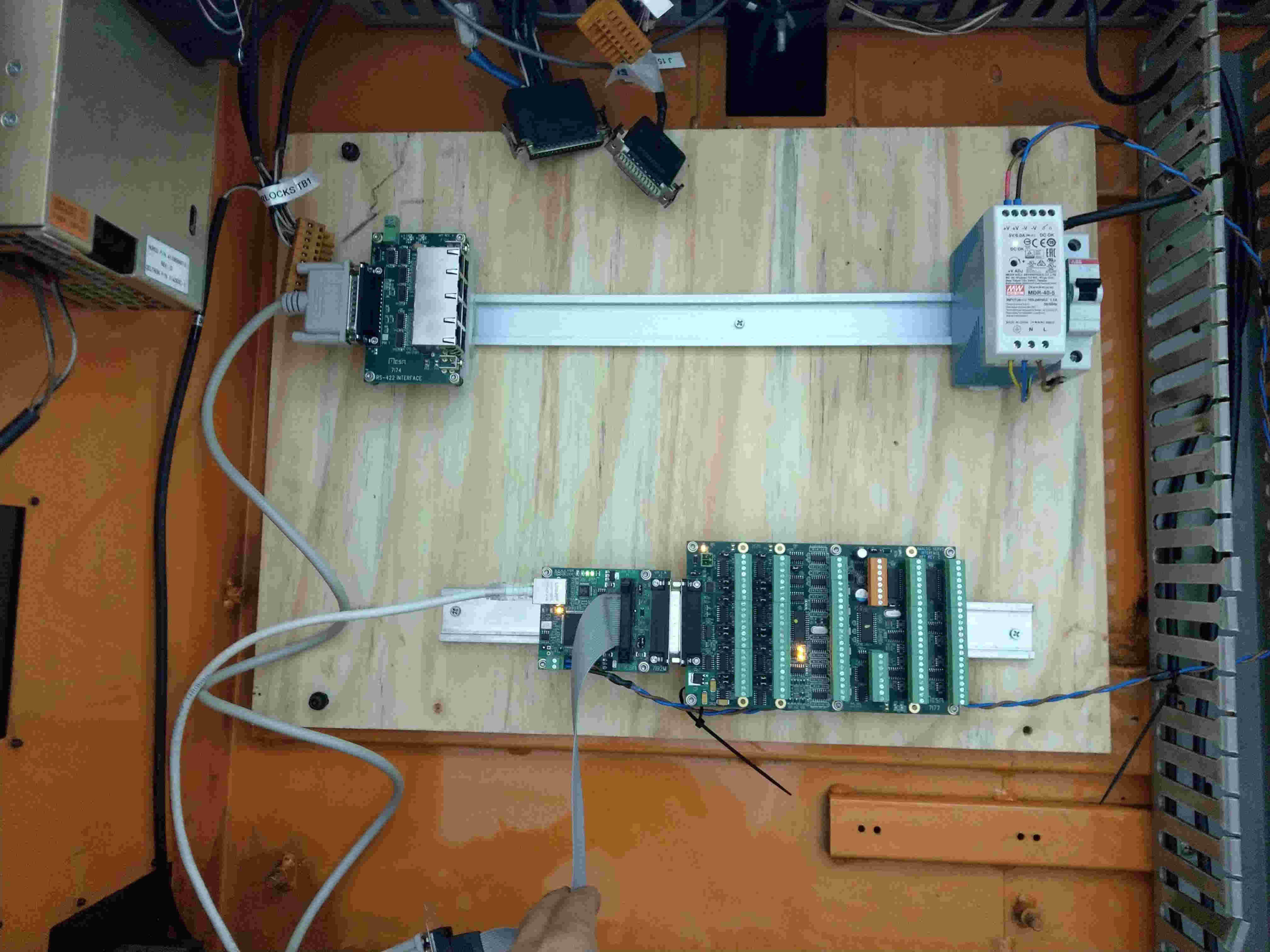
Attachments:
Last edit: 20 Aug 2022 20:26 by christos.
Please Log in or Create an account to join the conversation.
- tommylight
-
- Offline
- Moderator
-
Less
More
- Posts: 21625
- Thank you received: 7383
20 Aug 2022 21:06 #250128
by tommylight
No grounding, they are grounded on the drive side, so mesa side=no grounding.
Replied by tommylight on topic One more HURCO BMC 20P Retrofit
That is OK.“Phase A ” to “QA0”
“Phase A-” to “/QA0”
“Phase B ” to “QB0”
“Phase B-” to “/QB0”
“Marker ” to “IDX0”
“Marker -” to “/IDX0”
PA0 etc are the drive to encoder side of things, that remains untouched. Those are not normal incremental encoders so can not be used directly (and a real pain to remove from motors)......and on the Yaskawa manual, the symbols are “PAO, *PAO, PBO,*PBO, PCO, *PCO).
Do I have to ground these connections back from the 7i77 to the yaskawa servopack?
No grounding, they are grounded on the drive side, so mesa side=no grounding.
I do remember, i used the existing one after a bit of monitoring as the 24V would wander a bit, up to 26.4V, and that was still OK so i left it in.Also a special query for tommylight: Could you remember if you used new PSUs for the 5/12/24V or did you use the one that is already inside the cabinet (left top side)?
The following user(s) said Thank You: christos
Please Log in or Create an account to join the conversation.
- christos
- Offline
- New Member
-
Less
More
- Posts: 15
- Thank you received: 3
21 Aug 2022 20:30 - 21 Aug 2022 20:32 #250156
by christos
Replied by christos on topic One more HURCO BMC 20P Retrofit
Hello, once more.
It’s getting late down here and I'm beginning to realize that I’m might be missing basic electrical knowledge to understand how things inside my cnc machine were working… Having as a guidance the initial wiring diagrams from the Hurco, I’m trying to understand how to connect my X/Y/Z limit switches to the 7i77D.
Apologies if what I’m trying to achieve is not clear enough.
Starting with a 24V from the DC power and passing through a lot of “junctions” within the old Hurco controller, we end up in connector “J16”.
J16, pin 2 was to +X Limit switch (N.O.) and then ends up in J16 pin 1.
J16, pin 6 was to +X Limit switch (N.O.) and then ends up in J16 pin 5.
J16, pin 9 was to +Y Limit switch (N.O.) and then ends up in J16 pin 8.
J16, pin 13 was to -Y Limit switch (N.O.) and then ends up in J16 pin 12.
J16, pin 16 was to -Z Limit switch (N.O.) and then ends up in J16 pin 19.
J16, pin 20 was to +Z Limit switch (N.O.) and then ends up in J16 pin 15.
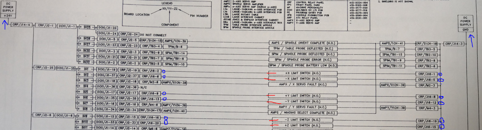
All end pins are to be grounded back to the power supply.Photo of the wiring diagram is attached.
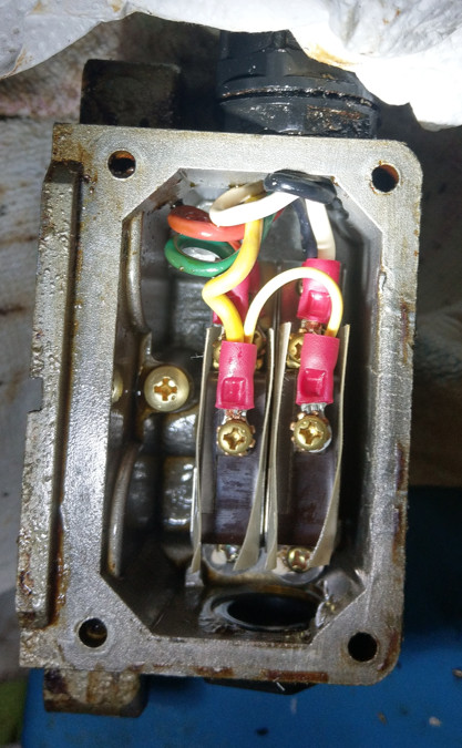
Now, my limit switches are “Micro LDV5202”, there are fairly limited datasheets, so I have opened up one to have a look (specifically the Y-axis). These are double pins but with two separate limits switches within (one hits the negative and the other the positive ends of travel). All three axis have the same limit switches, so I would have to assume that their wiring is identical. Inside the switch there are in total 5 cables, one cable is shared within the two limit switches. I have found that the limit switches inside are “Honewell AS-J215” but no more information is available…So basically we have the following connection in each limit switch:
Switch 1 -> Yellow, Green, and Red.
Switch 2 -> Yellow, White, and Black.
Photo of the opened up casing of the limit switches attached.
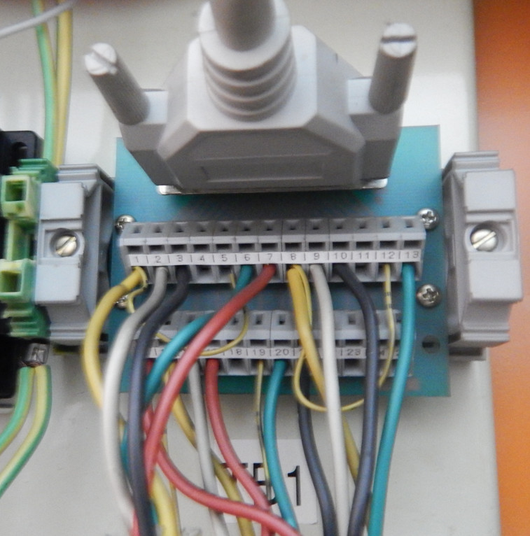
Going back to the Hurco, in the “TB1” where all these wires end up, I see the how the connections are being done and by combining the initial wiring diagram of the connector J16 I end up with the following for Y-axis only:
24V to J16, pin 9 (WHITE cable) was to +Y Limit switch (N.O.) and then ends up in J16 pin 8 (YELLOW cable) to ground.
24V to J16, pin 13 (GREEN cable) was to -Y Limit switch (N.O.) and then ends up in J16 pin 12 (YELLOW cable) to ground.
I can’t find any information about the RED and BLACK cable which comes from the limit switches, or any information in the wiring diagrams about pins 7 and 10 which are terminated.
Photo of the connector attached.
Now the questions:
a) Are the any ideas, how to check what is the red and black cables? And whether these are needed somehow.
b) If I had to assume, I would put 24V on the specified pins (WHITE and GREEN) and return the end pins (which previously were going to ground) as an input to my 7i77. Will that work, or I will end up burning my 7i77 since I can’t control how much amps will go through the limit switches?
If I’m asking something that has been done again, please point me to the right direction.
It’s getting late down here and I'm beginning to realize that I’m might be missing basic electrical knowledge to understand how things inside my cnc machine were working… Having as a guidance the initial wiring diagrams from the Hurco, I’m trying to understand how to connect my X/Y/Z limit switches to the 7i77D.
Apologies if what I’m trying to achieve is not clear enough.
Starting with a 24V from the DC power and passing through a lot of “junctions” within the old Hurco controller, we end up in connector “J16”.
J16, pin 2 was to +X Limit switch (N.O.) and then ends up in J16 pin 1.
J16, pin 6 was to +X Limit switch (N.O.) and then ends up in J16 pin 5.
J16, pin 9 was to +Y Limit switch (N.O.) and then ends up in J16 pin 8.
J16, pin 13 was to -Y Limit switch (N.O.) and then ends up in J16 pin 12.
J16, pin 16 was to -Z Limit switch (N.O.) and then ends up in J16 pin 19.
J16, pin 20 was to +Z Limit switch (N.O.) and then ends up in J16 pin 15.
All end pins are to be grounded back to the power supply.Photo of the wiring diagram is attached.
Now, my limit switches are “Micro LDV5202”, there are fairly limited datasheets, so I have opened up one to have a look (specifically the Y-axis). These are double pins but with two separate limits switches within (one hits the negative and the other the positive ends of travel). All three axis have the same limit switches, so I would have to assume that their wiring is identical. Inside the switch there are in total 5 cables, one cable is shared within the two limit switches. I have found that the limit switches inside are “Honewell AS-J215” but no more information is available…So basically we have the following connection in each limit switch:
Switch 1 -> Yellow, Green, and Red.
Switch 2 -> Yellow, White, and Black.
Photo of the opened up casing of the limit switches attached.
Going back to the Hurco, in the “TB1” where all these wires end up, I see the how the connections are being done and by combining the initial wiring diagram of the connector J16 I end up with the following for Y-axis only:
24V to J16, pin 9 (WHITE cable) was to +Y Limit switch (N.O.) and then ends up in J16 pin 8 (YELLOW cable) to ground.
24V to J16, pin 13 (GREEN cable) was to -Y Limit switch (N.O.) and then ends up in J16 pin 12 (YELLOW cable) to ground.
I can’t find any information about the RED and BLACK cable which comes from the limit switches, or any information in the wiring diagrams about pins 7 and 10 which are terminated.
Photo of the connector attached.
Now the questions:
a) Are the any ideas, how to check what is the red and black cables? And whether these are needed somehow.
b) If I had to assume, I would put 24V on the specified pins (WHITE and GREEN) and return the end pins (which previously were going to ground) as an input to my 7i77. Will that work, or I will end up burning my 7i77 since I can’t control how much amps will go through the limit switches?
If I’m asking something that has been done again, please point me to the right direction.
Attachments:
Last edit: 21 Aug 2022 20:32 by christos.
Please Log in or Create an account to join the conversation.
- smc.collins
- Offline
- Platinum Member
-
Less
More
- Posts: 723
- Thank you received: 139
21 Aug 2022 21:10 #250160
by smc.collins
Replied by smc.collins on topic One more HURCO BMC 20P Retrofit
what voltages are on the red and black wires ? are these reed type hall efffect switches or mechanical ????
Please Log in or Create an account to join the conversation.
- tommylight
-
- Offline
- Moderator
-
Less
More
- Posts: 21625
- Thank you received: 7383
21 Aug 2022 22:02 #250166
by tommylight
Replied by tommylight on topic One more HURCO BMC 20P Retrofit
Leave the wiring as is.
The only thing needed is wiring each switch to Mesa inputs while leaving everything as is.
The homing will need a bit of tuning though, to find the max speed for home_search_velocity as not to exceed the switch to much. Setting low homing speed initially is essential, for all homing related moves.
This way you have the limits in LinuxCNC and in the drives.
Please Log in or Create an account to join the conversation.
- christos
- Offline
- New Member
-
Less
More
- Posts: 15
- Thank you received: 3
21 Aug 2022 22:21 #250168
by christos
Replied by christos on topic One more HURCO BMC 20P Retrofit
These are mechanical, specifically "Honewell AS-J215" limit switches.
Since I have dismantled all the previous controls, at the moment I do not have a way of knowing whether voltage was passing through.
But you gave me an idea, if I could power them up externally to see if I press them if voltage changes.
Since I have dismantled all the previous controls, at the moment I do not have a way of knowing whether voltage was passing through.
But you gave me an idea, if I could power them up externally to see if I press them if voltage changes.
Please Log in or Create an account to join the conversation.
Time to create page: 0.375 seconds