ATC with carousel.comp and M6 remap
- gmarconi2
- Offline
- Junior Member
-

Less
More
- Posts: 36
- Thank you received: 5
04 Mar 2019 20:14 #127726
by gmarconi2
Replied by gmarconi2 on topic ATC with carousel.comp and M6 remap
This is a working configuration of a 3-axis milling machine with a spindle and a 10-pocket ATC (carousel.comp Master)
carousel feedback is simulated with switch and relay in a breadboard.
The arm is driven by a motor, as is the carousel.
In my case the step motor and I use an Arduino interface to generate step dir, but I will try to follow the advice of "Andypugh"
to drive the engines with stepgen in velocity.
Greetings gmarconi2
Attachments:
The following user(s) said Thank You: akb1212, pl7i92
Please Log in or Create an account to join the conversation.
- pl7i92
-

- Offline
- Platinum Member
-

Less
More
- Posts: 1872
- Thank you received: 358
05 Mar 2019 11:46 #127779
by pl7i92
Replied by pl7i92 on topic ATC with carousel.comp and M6 remap
Thank you very mutch this might give som otheres a good startpoint
Please Log in or Create an account to join the conversation.
- gmarconi2
- Offline
- Junior Member
-
Less
More
- Posts: 36
- Thank you received: 5
10 Mar 2019 21:26 - 10 Mar 2019 21:28 #128272
by gmarconi2
Replied by gmarconi2 on topic ATC with carousel.comp and M6 remap
Goodmorning everyone
I use a fanuc AC spindle with a quadrature pulse generator without index, I can use it to see the actual speed.
I can control the spindle correctly, I have enabled spindle encoder on mesa 5i25-7i76 but in the hal file I do not see the pins of signals A and B.
I only see:
#*******************
# SPINDLE S
#*******************
setp pid.s.Pgain [SPINDLE_9]P
setp pid.s.Igain [SPINDLE_9]I
setp pid.s.Dgain [SPINDLE_9]D
setp pid.s.bias [SPINDLE_9]BIAS
setp pid.s.FF0 [SPINDLE_9]FF0
setp pid.s.FF1 [SPINDLE_9]FF1
setp pid.s.FF2 [SPINDLE_9]FF2
setp pid.s.deadband [SPINDLE_9]DEADBAND
setp pid.s.maxoutput [SPINDLE_9]MAX_OUTPUT
setp pid.s.error-previous-target true
net spindle-index-enable <=> pid.s.index-enable
net spindle-enable => pid.s.enable
net spindle-vel-cmd-rpm-abs => pid.s.command
net spindle-vel-fb-rpm-abs => pid.s.feedback
net spindle-output <= pid.s.output
# ---digital potentionmeter output signals/setup---
setp hm2_5i25.0.7i76.0.0.spinout-minlim [SPINDLE_9]OUTPUT_MIN_LIMIT
setp hm2_5i25.0.7i76.0.0.spinout-maxlim [SPINDLE_9]OUTPUT_MAX_LIMIT
setp hm2_5i25.0.7i76.0.0.spinout-scalemax [SPINDLE_9]OUTPUT_SCALE
net spindle-output => hm2_5i25.0.7i76.0.0.spinout
net spindle-enable => hm2_5i25.0.7i76.0.0.spinena
net spindle-ccw => hm2_5i25.0.7i76.0.0.spindir
# ---Encoder feedback signals/setup---
setp hm2_5i25.0.encoder.00.counter-mode 0
setp hm2_5i25.0.encoder.00.filter 1
setp hm2_5i25.0.encoder.00.index-invert 0
setp hm2_5i25.0.encoder.00.index-mask 0
setp hm2_5i25.0.encoder.00.index-mask-invert 0
setp hm2_5i25.0.encoder.00.scale [SPINDLE_9]ENCODER_SCALE
net spindle-revs <= hm2_5i25.0.encoder.00.position
net spindle-vel-fb-rps <= hm2_5i25.0.encoder.00.velocity
net spindle-index-enable <=> hm2_5i25.0.encoder.00.index-enable
# ---setup spindle control signals---
net spindle-vel-cmd-rps <= motion.spindle-speed-out-rps
net spindle-vel-cmd-rps-abs <= motion.spindle-speed-out-rps-abs
net spindle-vel-cmd-rpm <= motion.spindle-speed-out
net spindle-vel-cmd-rpm-abs <= motion.spindle-speed-out-abs
net spindle-enable <= motion.spindle-on
net spindle-cw <= motion.spindle-forward
net spindle-ccw <= motion.spindle-reverse
net spindle-brake <= motion.spindle-brake
net spindle-revs => motion.spindle-revs
net spindle-at-speed => motion.spindle-at-speed
net spindle-vel-fb-rps => motion.spindle-speed-in
net spindle-index-enable <=> motion.spindle-index-enable
# ---Setup spindle at speed signals---
net spindle-vel-cmd-rps => near.0.in1
net spindle-vel-fb-rps => near.0.in2
net spindle-at-speed <= near.0.out
setp near.0.scale 1.000000
setp near.0.difference 3.333333
# **** Usa velocità mandrino EFFETTIVA dall'encoder mandrino
# spindle-velocity intermittente pertanto viene filtrata con passabasso
# **** velocità mandrino con il segno, pertanto usa componente assoluta per rimuovere il segno
# **** velocità EFFETTIVA è in giri/s e non giri/min pertanto viene scalata.
setp scale.spindle.gain 60
setp lowpass.spindle.gain 1.000000
net spindle-vel-fb-rps => scale.spindle.in
net spindle-fb-rpm scale.spindle.out => abs.spindle.in
net spindle-fb-rpm-abs abs.spindle.out => lowpass.spindle.in
net spindle-fb-rpm-abs-filtered lowpass.spindle.out
Greetings gmarconi2
Last edit: 10 Mar 2019 21:28 by gmarconi2.
Please Log in or Create an account to join the conversation.
- tommylight
-

- Offline
- Moderator
-

Less
More
- Posts: 21765
- Thank you received: 7438
11 Mar 2019 03:58 #128282
by tommylight
Replied by tommylight on topic ATC with carousel.comp and M6 remap
Encoder A and B can be seen in halmeter or in the hal configuration menu in linuxcnc.
In hal they are referred to only as encoder.n.
In hal they are referred to only as encoder.n.
The following user(s) said Thank You: gmarconi2
Please Log in or Create an account to join the conversation.
- gmarconi2
- Offline
- Junior Member
-
Less
More
- Posts: 36
- Thank you received: 5
17 Apr 2019 10:25 #131050
by gmarconi2
Replied by gmarconi2 on topic ATC with carousel.comp and M6 remap
Good morning
I have an incremental encoder in the spindle motor, and everything works.
In reality however the spindle motor is coupled to the spindle with a belt, can I continue to use the encoder channels A and B on the spindle motor, and use index on the spindle?
Greetings Giampiero
I have an incremental encoder in the spindle motor, and everything works.
In reality however the spindle motor is coupled to the spindle with a belt, can I continue to use the encoder channels A and B on the spindle motor, and use index on the spindle?
Greetings Giampiero
Please Log in or Create an account to join the conversation.
- tommylight
-
- Offline
- Moderator
-
Less
More
- Posts: 21765
- Thank you received: 7438
17 Apr 2019 17:03 #131061
by tommylight
Replied by tommylight on topic ATC with carousel.comp and M6 remap
In general, yes, granted the count from index to index will not change due to reduction.
I do not know what happens if the count is not constant.
I do not know what happens if the count is not constant.
The following user(s) said Thank You: gmarconi2
Please Log in or Create an account to join the conversation.
- GuiHue
-

- Offline
- Premium Member
-

Less
More
- Posts: 112
- Thank you received: 39
21 Oct 2019 16:18 #148481
by GuiHue
Replied by GuiHue on topic ATC with carousel.comp and M6 remap
Dear all,
I'm sorry for opening an old topic again. I am currently evaluating different options regarding an ATC setup. Rack and carousel are both viable options for me. With Carousel having the added bonus of being available as a comp.
Reading through this thread there is one thing that has me puzzled:
What kind of sensors are used and how are they operated. gmarconi2 has two sensors in use which I assume relate to:
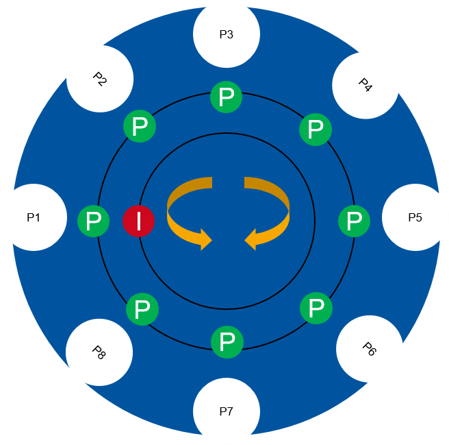
carousel.N.sense-M bit in (M=0..personality):
Carousel position feedback pins. In ’index’ mode there will be only 2 pins. sense-0 is the index and sense-1 is the pocket sensor.
I have drawn up a simple sketch to illustrate my interpretation and would greatly appreciate any feedback as to whether or not this is correct.
I have assumed what follows:
-Sense-0 and sense-1 are both inductive sensor looking for targets on different diameters around the axis of rotation
-Sense-0 is looking for an index ((red target labeled I); 1 target on circumference); = home = Pocket 1 (or 0)
-Sense-1 is looking for a target for each pocket (green targets, labeled P), carousel uses this to know how far it has travelled (hence the use of velocity mode over distance)
@gmarconi2: Have you ever followed up an Andys lead regarding the use of step/dir?
I'm sorry for opening an old topic again. I am currently evaluating different options regarding an ATC setup. Rack and carousel are both viable options for me. With Carousel having the added bonus of being available as a comp.
Reading through this thread there is one thing that has me puzzled:
What kind of sensors are used and how are they operated. gmarconi2 has two sensors in use which I assume relate to:
carousel.N.sense-M bit in (M=0..personality):
Carousel position feedback pins. In ’index’ mode there will be only 2 pins. sense-0 is the index and sense-1 is the pocket sensor.
I have drawn up a simple sketch to illustrate my interpretation and would greatly appreciate any feedback as to whether or not this is correct.
I have assumed what follows:
-Sense-0 and sense-1 are both inductive sensor looking for targets on different diameters around the axis of rotation
-Sense-0 is looking for an index ((red target labeled I); 1 target on circumference); = home = Pocket 1 (or 0)
-Sense-1 is looking for a target for each pocket (green targets, labeled P), carousel uses this to know how far it has travelled (hence the use of velocity mode over distance)
@gmarconi2: Have you ever followed up an Andys lead regarding the use of step/dir?
Attachments:
Please Log in or Create an account to join the conversation.
- andypugh
-

- Offline
- Moderator
-
Less
More
- Posts: 19886
- Thank you received: 4645
23 Oct 2019 23:28 #148654
by andypugh
Replied by andypugh on topic ATC with carousel.comp and M6 remap
carousel.comp can use a variety of different sensor setups.
For your 8-position carousel I think I would use 4 sensors, 3 x absolute binary coding 0 to 7 and 1 index / strobe.
For your 8-position carousel I think I would use 4 sensors, 3 x absolute binary coding 0 to 7 and 1 index / strobe.
Please Log in or Create an account to join the conversation.
- gmarconi2
- Offline
- Junior Member
-
Less
More
- Posts: 36
- Thank you received: 5
24 Oct 2019 07:15 #148677
by gmarconi2
Replied by gmarconi2 on topic ATC with carousel.comp and M6 remap
241/5000
Yes your system is the one I used, the two index and sense sensors are on the same line in position 1 then in every sense sensor pocket only.
I used stepper motors, commanded with arduino, I modified the m6 routine and everything works.
Yes your system is the one I used, the two index and sense sensors are on the same line in position 1 then in every sense sensor pocket only.
I used stepper motors, commanded with arduino, I modified the m6 routine and everything works.
Please Log in or Create an account to join the conversation.
- GuiHue
-
- Offline
- Premium Member
-
Less
More
- Posts: 112
- Thank you received: 39
29 Oct 2019 22:59 #149080
by GuiHue
Replied by GuiHue on topic ATC with carousel.comp and M6 remap
Thank you both for getting back to me.
While an additional arduino would do the trick, I’d rather avoid that hassle.
@andypugh:
That would certainly be an option, however, when the carousel gets larger (chaindrive maybe?) it seems not very practical. Hence my simplified approach. Would that work with your component? (Although it would be less safe).
Is there an alternative for an Encoder you would recommend at 16+ nests?
Please Log in or Create an account to join the conversation.
Time to create page: 0.130 seconds