- Configuring LinuxCNC
- Advanced Configuration
- EtherCAT
- Beckhoff ethercat 64 with bit linuxcnc, How to install.
Beckhoff ethercat 64 with bit linuxcnc, How to install.
- Grotius
-
 Topic Author
- Offline
- Platinum Member
-

Less
More
- Posts: 2419
- Thank you received: 2348
18 Jan 2019 21:55 - 18 Jan 2019 21:58 #124417
by Grotius
Replied by Grotius on topic Beckhoff ethercat 64 with bit linuxcnc, How to install.
I am almost at the moment to install my first ethercat hardware on real machine.
Spec's of this board:
4 axis stepper, config XXYZ, home sense X0+X1+Probe (+5 input spare on stepper drives)
1 analog input for torch height control (+1 analog input spare)
1 relais output for torch on/off (+3 output's spare)
1 24Vdc power supply
1 50Vdc power supply
But houston we have a little problem. First i have to write a new driver for the torch on output.
- EL2794 ( 4 channel solid state relais )
Later to do, interfacing plasma power output. At this moment i can do this with modbuss python on a Hypertherm.
But i am looking to connect a Thermal dynamic's inverter serie's up to 120 Amp's. There is no power interface available at this moment, i had indirect contact with the factory develop, but without information succces.")
So i have to make a power setting's connection inside the inverter soon by myself.
The inverter has a digital pulse type potentiometer. That type is not so easy to connect to extern component's, because the begin value of potientio is alway's lost in that way. Maybe i bring the inverter to electronic expert to look at.
Spec's of this board:
4 axis stepper, config XXYZ, home sense X0+X1+Probe (+5 input spare on stepper drives)
1 analog input for torch height control (+1 analog input spare)
1 relais output for torch on/off (+3 output's spare)
1 24Vdc power supply
1 50Vdc power supply
But houston we have a little problem. First i have to write a new driver for the torch on output.
- EL2794 ( 4 channel solid state relais )
Later to do, interfacing plasma power output. At this moment i can do this with modbuss python on a Hypertherm.
But i am looking to connect a Thermal dynamic's inverter serie's up to 120 Amp's. There is no power interface available at this moment, i had indirect contact with the factory develop, but without information succces.
So i have to make a power setting's connection inside the inverter soon by myself.
The inverter has a digital pulse type potentiometer. That type is not so easy to connect to extern component's, because the begin value of potientio is alway's lost in that way. Maybe i bring the inverter to electronic expert to look at.
Last edit: 18 Jan 2019 21:58 by Grotius.
Please Log in or Create an account to join the conversation.
- rodw
-

- Offline
- Platinum Member
-
Less
More
- Posts: 12007
- Thank you received: 4089
18 Jan 2019 22:41 - 18 Jan 2019 22:44 #124419
by rodw
Replied by rodw on topic Beckhoff ethercat 64 with bit linuxcnc, How to install.
I had a look at the circuit diagrams n the A120 manual the other day.
www.esabna.com/eu/literature/plasma%20eq...utomation/0-4989.pdf
I think I would see if I could find a 40 pin connector breakout board (or make my own.) This might work.
au.element14.com/kitronik/5601b/breakout...connector/dp/2563845
This would give access to all pins on the console at J2.
I would observe the voltage at pin 6 - CUR_SET when turning the knob. I think it will vary from 0-5 volts if the gas control circuit on J4 is anything to go by. BUt if it is 12v or 3.3 volt, it would be very easy to pick up the power from the relevant pin and send the varying output to pin 6. Otherwise, you need a 12v to 5v step down power module or pick up 5 volts from the control board (J4-pin1). Maybe you could add a switch on pin 6 that switched between the current setting on the control panel and your potentiometer.
Also I would consider adding a 150 amp ACS758 current sensor in the power supply on the raw arc signal so you could give feedback to your control system..
You can buy prebuilt modules on ebay
www.ebay.com.au/itm/ACS758KCB-150B-AC-DC...e-newAU/323208224588
Good luck.
Last edit: 18 Jan 2019 22:44 by rodw.
Please Log in or Create an account to join the conversation.
- Grotius
-
Topic Author
- Offline
- Platinum Member
-
Less
More
- Posts: 2419
- Thank you received: 2348
18 Jan 2019 22:56 - 18 Jan 2019 23:00 #124420
by Grotius
Replied by Grotius on topic Beckhoff ethercat 64 with bit linuxcnc, How to install.
Hi Rod,
It's the 40 pin ribbon cable that does all the i/o. It's kind of confusing there is also a 15 volt department available on the ribbon cable. In total 3 type of voltage channel's. The pulse type potientiometer has a push function. this is easy to capture.
The fact is. At the moment i was testing the inverter i had only one inverter in the company and i had to cut next day.
Now i have more on stock, so i can test. If it burn's out there is no problem next day.
The ribbon adapter you sent in your link is the perfect way to test the application. All pin's are covered with hard wax. So measuring is also not easy at this moment without scraping first the hard way away.
I will test it with a new 40i inverter coming day's.
The purpose is to make an ethercat connection to the inverter. Maybe it will end in 2 pieces of 40 pin ribbon cable adapters, with
a analog ethercat output module beween it. If there are more connection's available i will let it know.
Almost forgotten, the inverter's have a selectable internal voltage divider with different ratio's.
Results in 0-10 volt analog in can be used on the ethercat side, that has a resolution of 16 bit.
Did you buy the inverter?
Last edit: 18 Jan 2019 23:00 by Grotius.
Please Log in or Create an account to join the conversation.
- rodw
-
- Offline
- Platinum Member
-
Less
More
- Posts: 12007
- Thank you received: 4089
19 Jan 2019 01:39 #124427
by rodw
Replied by rodw on topic Beckhoff ethercat 64 with bit linuxcnc, How to install.
Yes, I think a custom board that the ribbon cables from the inverter, the control panel and some terminals your Ethercat interface is the way to go. You can buy the ribbon cable and IDC connectors that crimp on in a vice. Very simple to make ribbon cables if they've used standard connectors ")
I have not bought the inverter yet. Tossing up between the Hypertherm and the Thermal Dynamics. I received a refund from our Tax Office yesterday that was overdue by their error. Next week, I will decide. It would be quite useful at the moment for the product development I am doing...
I have not bought the inverter yet. Tossing up between the Hypertherm and the Thermal Dynamics. I received a refund from our Tax Office yesterday that was overdue by their error. Next week, I will decide. It would be quite useful at the moment for the product development I am doing...
Please Log in or Create an account to join the conversation.
- Grotius
-
Topic Author
- Offline
- Platinum Member
-
Less
More
- Posts: 2419
- Thank you received: 2348
22 Jan 2019 13:13 #124610
by Grotius
Replied by Grotius on topic Beckhoff ethercat 64 with bit linuxcnc, How to install.
Hi Rod,
I mentioned your manual is different then the 40i and 60i manual.
The interfacing of the power button is different at the 120 amp's inverter.
The 40i/60i has a power button based on a kind of rotary encoder, pulse type.
It was not easy, but it's now done. I soldered a 3-wire cable on the print.
I wrote a software component called POWER.comp that does the work for adjustment very nice.
The beckhoff EL2794 is a 4 channel solid state relais. This one uses 2 relais to adjust the power.
I had to write the EL2794 driver also. For reader's don't buy the EL7041 without the -1000 extension. So order only
EL7041-1000. The EL7041 works on the EL7041-1000 driver, but is about 30% slower trough the slower in motor output speed
using the slower internal encoder.
Now i am going to look, to adapt the kerf width offset into variable g-code, for G41/42 procedure's. When that is done,
The environment is almost independent of cam.
Attachments:
Please Log in or Create an account to join the conversation.
- rodw
-
- Offline
- Platinum Member
-
Less
More
- Posts: 12007
- Thank you received: 4089
22 Jan 2019 20:32 #124632
by rodw
Replied by rodw on topic Beckhoff ethercat 64 with bit linuxcnc, How to install.
Very nice work. Ethercat certainly makes for a very neat installation. Are you going to run steppers or servos from the step and direction outputs? Will you add more IO modules for your limit and home switches etc?
Please Log in or Create an account to join the conversation.
- Grotius
-
Topic Author
- Offline
- Platinum Member
-
Less
More
- Posts: 2419
- Thank you received: 2348
28 Jan 2019 20:32 - 28 Jan 2019 20:49 #125093
by Grotius
Replied by Grotius on topic Beckhoff ethercat 64 with bit linuxcnc, How to install.
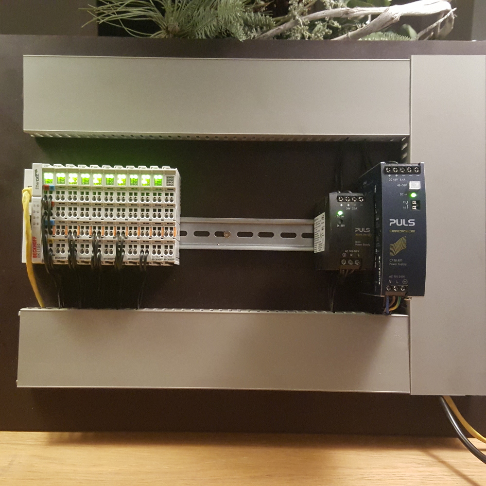
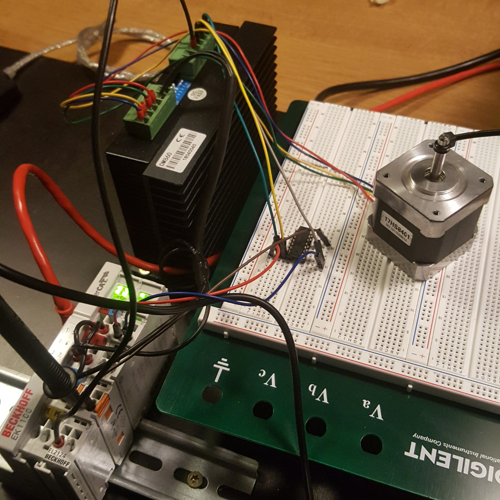
Hi Rod my friend,
Today i made some Ethercat progress, but at the beginning i made first a smoke curtain at my factory and blown a EL2124 and a secondairy chip away on a 24 vdc circuit. Cheise. So at home i had a second EL2124... To try with. It's a small stepper at the picture to test with. It stay's alive at 2 amps.
The Beckhoff stepper drives are 50v 5amp's. This was to less power to drive my gantry portal x axis motor's after testing.
So Houston i have a problem.
I was looking for a solution. Watching youtube about the transistor. And i ordered a chip that works like a transistor.
Minimum order was 30 chips, so it was a bit risky to order if the test would fail. I also ordered a breadboard.
But finally it succeeded after tuning the Ethercat software side. Now i can drive my machine with 80 volts 8 amps on Ethercat. Also the price is reduced from Euro 250 a drive to Euro 50 a drive. I now use a EL2124 to guide 4 stepgen signals ( 4 motor pulse train's )
I will test this config on the machine coming day's. I hope it's good on a real machine. This test set up, run's like a servo.
I mentioned ethercat has no reset, parport has. But after all, that's no problem.
Will you add more IO modules for your limit and home switches etc?
Yes, yes...
I add multi i/o. THC analog in is working, I add a gas valve for plasma marking. Argon / Air valve. + Argon preflow function.
So soon we are the marking masters at 10 amp's argon.
I have good news, one of my customer's bought a second machine. It has Grotius LInux on it. He was cutting 30 hours first week on his new 64 bit linux machine. He want's to get rid of window's on his first cutting machine.
Reason is, he can't do active THC on 2 oxy fuel torches while cutting. So z + a axis floating head's looks impossible on window's.
In linux this is peanut's
Attachments:
Last edit: 28 Jan 2019 20:49 by Grotius.
Please Log in or Create an account to join the conversation.
- Grotius
-
Topic Author
- Offline
- Platinum Member
-
Less
More
- Posts: 2419
- Thank you received: 2348
30 Jan 2019 19:49 - 30 Jan 2019 19:54 #125323
by Grotius
Replied by Grotius on topic Beckhoff ethercat 64 with bit linuxcnc, How to install.
I must add a correction reply.
The EL2124 can directly work on stepper drives like DM860.
I inverted the signal with ic. This works, but was not my problem.
I trapped my self in a software pre configure issue. Glad it works now without ic.
The pulse speed of the EL2124 is : typ. TON: < 1 µs, typ. TOFF: < 1 µs, so pulse timer looks quite quick. Ethercat is fastest protocol i read somewhere.
Solution is to make Ethercat read and write in base thread in stead of servo thread, in my case the timer is now 15000 in stead of 1000000. Machine speed's over 20 m/min with steppers. I stopped stable testing at 21 m/min.
Now beckhoff is coming to my factory to show some servo drives. I hope this will bring some luck. In the past i worked with Lenze
servo drives. So i am curious about their advise.
Keep up the good work !! And remember : if you do nothing, nothing will happen.
Last edit: 30 Jan 2019 19:54 by Grotius.
Please Log in or Create an account to join the conversation.
- shameless
- Offline
- Junior Member
-

Less
More
- Posts: 27
- Thank you received: 3
25 Feb 2019 08:30 #127091
by shameless
Replied by shameless on topic Beckhoff ethercat 64 with bit linuxcnc, How to install.
I like it when I first see it: If you do nothing, nothing will happen. But I am stuck in how to use HAL to make the motor run. 
But I am stuck in how to use HAL to make the motor run. Please Log in or Create an account to join the conversation.
- shameless
- Offline
- Junior Member
-
Less
More
- Posts: 27
- Thank you received: 3
23 Mar 2019 02:53 #129324
by shameless
Replied by shameless on topic Beckhoff ethercat 64 with bit linuxcnc, How to install.
Hi
I have a slave, IO module, which is not a beckhoff, but including DI,DO&AI, and I have done all the modifications to the .h&.c, until I finish all the steps. I start the Linuxcnc, the ethercat didn't change to OP, when I scan slaves, there shows a "E",indicating that there's a scan or configuration fault. So I just wanna know Is there any approached to locate the configuration error, so I can fix it.
Best regards!
Please Log in or Create an account to join the conversation.
- Configuring LinuxCNC
- Advanced Configuration
- EtherCAT
- Beckhoff ethercat 64 with bit linuxcnc, How to install.
Time to create page: 0.268 seconds