Spurious engagement of Plasmac's Anti-dive
- mkardasi
- Offline
- Senior Member
-

- Posts: 48
- Thank you received: 18
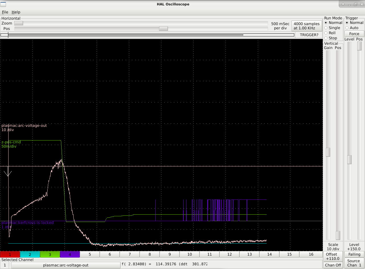
What I see is the triggering of plasmac anti-dive (kerf cross) even with the most aggressive setting (500% override, 0.002 height/volt).
Here is a straight cut with encoder.filter enabled and encoder.velocity pumped into lowpass.gain @ 0.467
Attachment not found
At this point I'm not sure if the false trigger is being caused by low I gain, signal jitter or the gravitational pull of the moon. Any advice would be greatly appreciated.
Please Log in or Create an account to join the conversation.
- rodw
-

- Offline
- Platinum Member
-

- Posts: 12047
- Thank you received: 4113
I have an alternative component I think will work but it will need some experimentation to pick a threshold to kick in at and also how best to turn it off. Plasmac has a pin for an external hold. I calculate a moving average of the rate of change in arc voltage per second so the threshold is something up around 6,000-10,000 when normal cutting is < 3,000 volts per second.
If you would like to play with it in halscope, contact me by completing the form here www.vehiclemods.net.au/contact-us
It would be good to have some help with this.
Please Log in or Create an account to join the conversation.
- mkardasi
- Offline
- Senior Member
-
- Posts: 48
- Thank you received: 18
I think its best to disable the kerf crossing at this stage. Phill can't work on it until he gets his table built but your plot indicates his algorithm is not right. A couple of us have tried and given up for now
I have an alternative component I think will work but it will need some experimentation to pick a threshold to kick in at and also how best to turn it off. Plasmac has a pin for an external hold. I calculate a moving average of the rate of change in arc voltage per second so the threshold is something up around 6,000-10,000 when normal cutting is < 3,000 volts per second.
If you would like to play with it in halscope, contact me by completing the form here www.vehiclemods.net.au/contact-us
It would be good to have some help with this.
Understood. I wasn't aware that the feature isn't quite ready. I have nothing against testing your component, I will contact you as you suggest.
Please Log in or Create an account to join the conversation.
- rodw
-
- Offline
- Platinum Member
-
- Posts: 12047
- Thank you received: 4113
Please Log in or Create an account to join the conversation.
- mkardasi
- Offline
- Senior Member
-
- Posts: 48
- Thank you received: 18
mkardasi Did you get my email? I had a bit of trouble with gmail thinking I was sending you a virus but I think I got it in the end...
Yes sir, I did. I'm working on the integration right now.
Please Log in or Create an account to join the conversation.
- Grotius
-

- Offline
- Platinum Member
-
- Posts: 2419
- Thank you received: 2348
It looks like the kerf crossing is ticking the upper and lower limits after a while.
20:1 is not a very good scale. Can the inverter do a 50 to 1 scale?
signal jitter or the gravitational pull of the moon
Strange that it happens in the stable voltage cut path. For me it looks like a boolean software jitter..
where lives this file : HALFILE = esab-plasmac.hal ?
Please Log in or Create an account to join the conversation.
- mkardasi
- Offline
- Senior Member
-
- Posts: 48
- Thank you received: 18
Looks like the torch is following the arc voltage ... Or am I wrong?
It looks like the kerf crossing is ticking the upper and lower limits after a while.
I agree. Torch follows arc voltage within the deadband of 1v. Then it locks out because kerf_threshold is exceeded.
* set kerfcross lock if voltage change > kerfcross threshold volts */
                            }else if(kerfcross_enable){
                                if(thc_feed_rate < current_velocity * 60){
                                    kerf_ratio = thc_feed_rate / (current_velocity * 60);
                                }else{
                                    kerf_ratio = 1; /* 45 degree ramp */
                                }
                                kerf_threshold = ((kerf_ratio * current_velocity * fperiod) / height_per_volt) * (kerfcross_override * 0.01);
                                if(arc_voltage > target_volts + kerf_threshold){
                                    kerfcross_is_locked = TRUE;
                                }else{
                                    last_arc_voltage = arc_voltage;
                                }
If I understand the code correctly. My kerf_ratio is set by else to 1 as (thc_feed_rate < (current_velocity * 60)) = FALSE ( 150 < ( 0.5 * 60)).
kerf_threshold = ((1 * 0.5 * 0.001) / 0.002) * ( 500 * 0.01 ) = 1.25v
kerf_ratio = 1
current_velocity = 30 IPM or 0.5 units/sec
fperiod = 0.001 sec
height/volt = 0.002 units/volt
kerf_override = 500
Based on if(arc_voltage > target_volts + kerf_threshold) I have to be within 1.25v of target cut voltage or kerf_cross disables the THC.
20:1 is not a very good scale. Can the inverter do a 50 to 1 scale?
This the machine's CNC output. I would have to modify it to increase the divder.
signal jitter or the gravitational pull of the moon
Strange that it happens in the stable voltage cut path. For me it looks like a boolean software jitter..
where lives this file : HALFILE = esab-plasmac.hal ?
I sorry but I don't understand the last question.
Please Log in or Create an account to join the conversation.
- Grotius
-
- Offline
- Platinum Member
-
- Posts: 2419
- Thank you received: 2348
Look inside the inverter for a dip switch.. I hope you have luck today !
I sorry but I don't understand the last question.
No problem. In your attached files, i cannot find this hal file : esab-plasmac.hal
It could be the error lives in that file. So that's why i mentioned the missing file...
It's loaded in your hal config. When it's not loaded, you get a message btw.
boolean software jitter..
A bool is a variable that can be only one or zero. I know plasmac loves bools. That's why i think it could be a bool.
Multiple bool = boolean'sss

Please Log in or Create an account to join the conversation.
- PCW
-

- Offline
- Moderator
-

- Posts: 17994
- Thank you received: 5281
Have you tried simply increasing the kerf crossing threshold to say 3V?
I wonder if a threshold that's more independent of feedback loop bandwidth
would work better (like DVDT of filtered voltage > some threshold) plus some
smarter recovery scheme like detecting the other edge of the kerf
(with DVDT < some other threshold)
It would be nice to see a plot of plasma voltage at an actual kerf crossing...
Please Log in or Create an account to join the conversation.
- rodw
-
- Offline
- Platinum Member
-
- Posts: 12047
- Thank you received: 4113
It would be nice to see a plot of plasma voltage at an actual kerf crossing...
Here you go, my one and only plasmac kerf crossing plot:
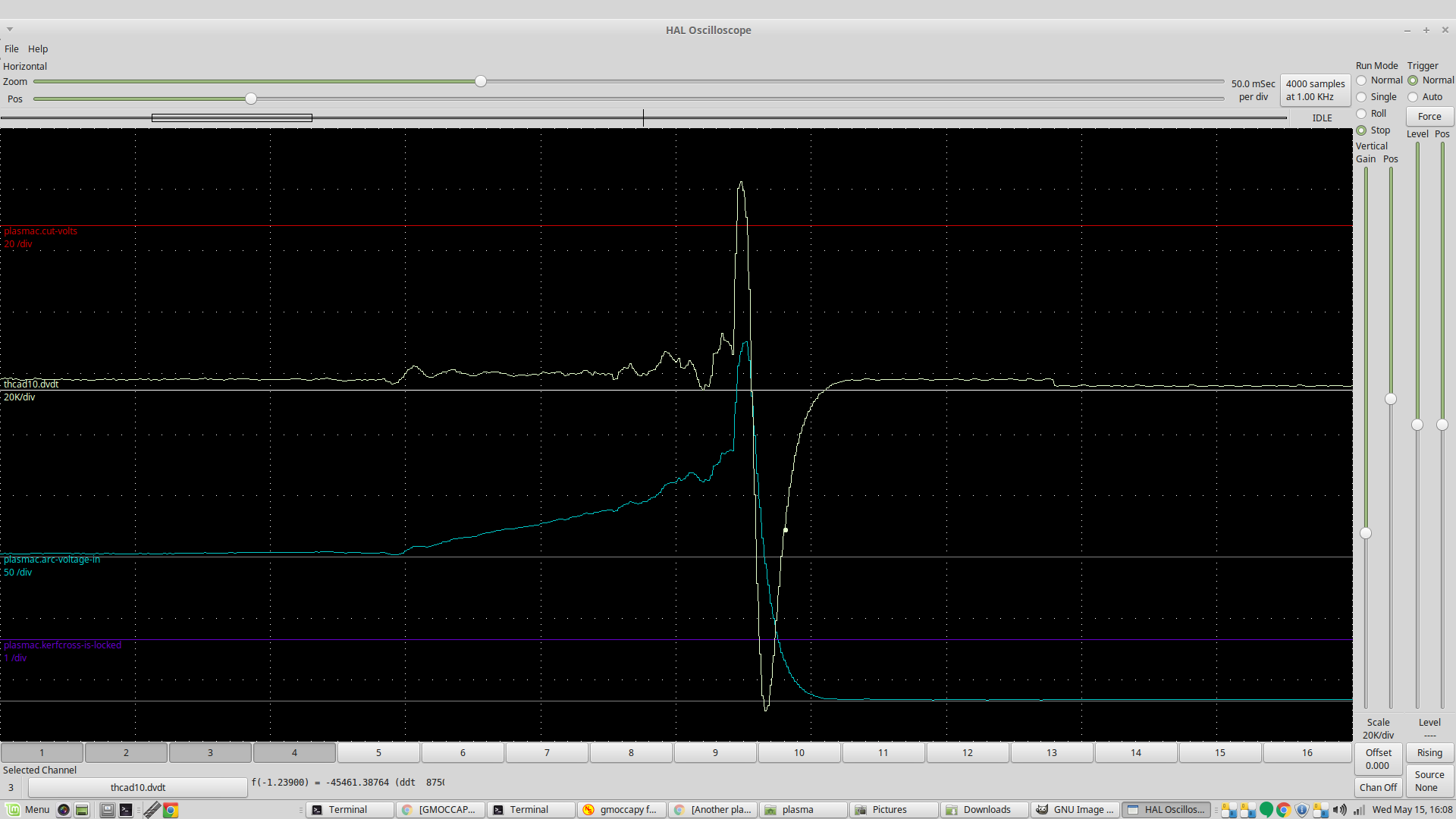
I don't think Plasmac's Kerf crossing algorithim is correct. It needs to be based on DV/DT which is shown on the plot above.
For the uninitiated, the DV/DT plot is hard to get your head around. Because its a rate of change, a constant increase in voltage will show as a flat line. So here you see as the torch runs out of material, there is a quick jump in DV/DT and then it skyrockets once its away from the material totally.
We need more data but I think a threshold set between the normal DV/DT behavior and the next flat line section would disable the THC in a few milliseconds.
This is a (much) earlier plot on my everlast from saved halsope data so the resolution is a bit coarse
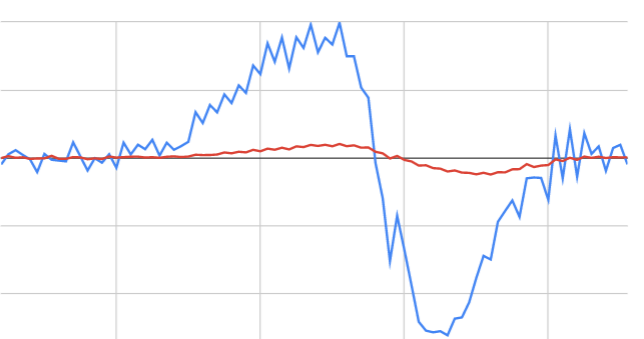
Shows DV/DT in blue and moving average in red.
I'm hoping mkardasi has the time to explore this. It takes some time to get halscope and everything set up just right!
Please Log in or Create an account to join the conversation.