Post Processor for LinuxCNC and PlasmaC
- phillc54
-

- Offline
- Platinum Member
-

- Posts: 5711
- Thank you received: 2100
I took some time off to do a bit of work on my table. I have finished the control panel and have all the axis moving. I just need to tune the velocity and acceleration then make sure the X and Y axes are perpendicular then I can begin hacking the plasma power supply.
Back on topic, Rod is correct, I have set it so you call out the actual percentage of velocity you require, so Q70 = 70%.
Anything above 100 is limited to 100% and below 10 is set to 100% as well to account for folk not using this feature and leaving the default at 0.
I hope that makes sense.
Cheers, Phill.
Please Log in or Create an account to join the conversation.
- islander261
- Offline
- Platinum Member
-
- Posts: 757
- Thank you received: 216
Sorry, my bad. I am a couple of updates behind the current Plasmac release and didn't know Phill was error checking and scaling in the code.
John
Please Log in or Create an account to join the conversation.
- phillc54
-
- Offline
- Platinum Member
-
- Posts: 5711
- Thank you received: 2100
Another way of achieving the end result would be instead of:
M67 E3 Q60F[#<_hal[plasmac.cut-feed-rate]> * 0.6]Cheers, Phill
Please Log in or Create an account to join the conversation.
- fupeama
-

- Offline
- Senior Member
-

- Posts: 66
- Thank you received: 14
....................
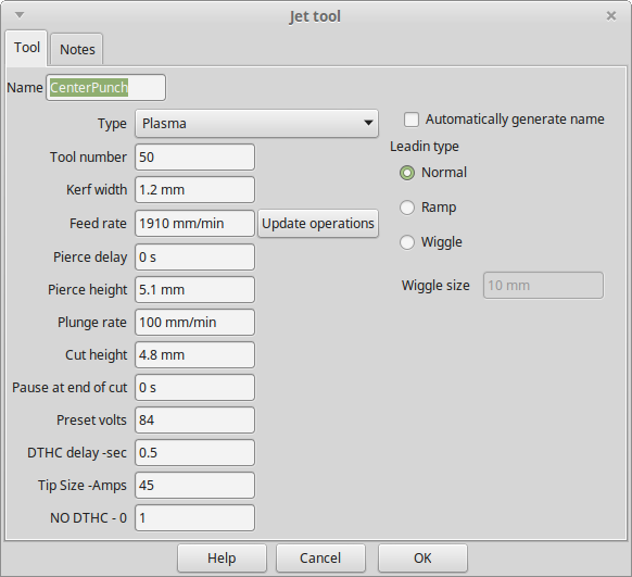
Also, create a tool called "CENTERPUNCH". Then if you have holes you just want to mark hole centres for subsequent drilling, you can create a new layer in sheetcam and move your holes to that layer. Then do a drill operation with the centerpunch tool on that layer and it will spot them for you. It is pretty cool watching plasmac swap the tools and updating the GUI on auto pilot!
Hi Rod,
what does it mean mark hole in this case?
Hole through all material or only mark on surface?
I need only little mark on surface for next drill operation.
In description on linuxcnc/docs is
A spindle on signal (connected to the plasmac.spindle-on input pin) begins the sequence of:
- set feedhold.
- find top of stock.
- move up to pierce height.
- start torch, retry if unsuccessful until too many attempts.
- wait for pierce delay.
- move to puddle jump height (if enabled).
- release feedhold, X/Y motion begins.
- wait for puddle jump delay (if enabled).
- move down to cutting height.
...
...
in your plasmac-sheetcam.ngc is
(Drill Process)
X50.000 Y17.500
F#<_hal[plasmac.cut-feed-rate]>
M3 S1
G1 X50.025 Y17.525 (Add tiny extension)
M5
G0 X50.000 Y17.500
if I understand it well, then I cant make mark on the surface. Is it true?
Thank Martin
Please Log in or Create an account to join the conversation.
- rodw
-

- Offline
- Platinum Member
-
- Posts: 11960
- Thank you received: 4074
Please Log in or Create an account to join the conversation.
- docwelch
- Offline
- Senior Member
-
- Posts: 58
- Thank you received: 25
I've been working on a post processor for Fusion 360 to use with plasmac. I've had a couple of thoughts I'd like to throw out for others to give me some feedback. I suspect the following could be implemented on other post processors as well without too much effort.
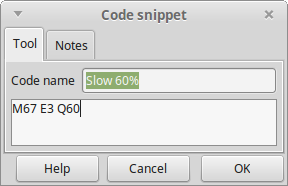
With respect to slowing down for small holes, what I am doing is having the post processor look to see if the arc being cut is a full circle and if that circle's diameter is <37 mm. If it meets those criteria, it will insert code to slow down the cut rate to 60%. I chose to use
F[#<_hal[plasmac.cut-feed-rate]> * 0.6]Along those same lines, I'm sure the kerf width will change when the speed is slowed but I don't know how much (still building my machine). If it is enough to be significant, I have a potential solution for that as well. If you are using offsets (G41.1 or G42.1), you should be able to adjust the offset when you adjust the speed for the smaller circle - something like
G42.1 D[#<_hal[plasmac_run.kerf-width-f]> + 0.25]I'd appreciate any thoughts - maybe you guys are already doing this but I have not seen it in any of the post processors.
Thanks,
Steven
Please Log in or Create an account to join the conversation.
- rodw
-
- Offline
- Platinum Member
-
- Posts: 11960
- Thank you received: 4074
Sheetcam outputs compensated code so you can't use offsets as you are.
You can't really adjust for speed from gcode as there is no way of knowing what the trajectory planner chooses to run plus it is all buffered so that line was read well before the motion occurs. There is an experimental branch called State tags that sends additional info about speeds back to motion that might help here. I really would like to see this incorporated into master for plasma users as I think it would close out some gaps. But don't hold your breath. Its 5 years old!
Please Log in or Create an account to join the conversation.
- phillc54
-
- Offline
- Platinum Member
-
- Posts: 5711
- Thank you received: 2100
I think this should work ok.With respect to slowing down for small holes, what I am doing is having the post processor look to see if the arc being cut is a full circle and if that circle's diameter is <37 mm. If it meets those criteria, it will insert code to slow down the cut rate to 60%. I chose to use
F[#<_hal[plasmac.cut-feed-rate]> * 0.6]
instead of the the M67 E3 Q60 simply because the feed rate will be reset "automatically" at the next move (another F#<_hal[plasmac.cut-feed-rate]> is sent with the next move which will get you back to the baseline).
You will probably need quite a few test cuts to calculate the change in kerf width vs velocity. It would be really nice if the change was linear, then you could just use one formula.Along those same lines, I'm sure the kerf width will change when the speed is slowed but I don't know how much (still building my machine). If it is enough to be significant, I have a potential solution for that as well. If you are using offsets (G41.1 or G42.1), you should be able to adjust the offset when you adjust the speed for the smaller circle - something like
G42.1 D[#<_hal[plasmac_run.kerf-width-f]> + 0.25]
would add 0.25 to the kerf width. Obviously, you would need to reset the kerf width before moving to the next cut.
Again, I think this should work ok.
Please Log in or Create an account to join the conversation.
- docwelch
- Offline
- Senior Member
-
- Posts: 58
- Thank you received: 25
Interesting that Sheetcam only outputs compensated code. Fusion 360 can do that (called "in computer compensation") but it can also output the exact path as if the tool has a 0 width and allow compensation to occur using the G41.1 and G42.1 codes (called "in machine compensation"). I have always used in computer compensation but finally found a potential reason to use the in machine compensation. Reading the Autodesk forum, they seem to indicate that most of the "high end" machines use in machine compensation.
Phill,
It would definitely require a lot of test cuts for the automated kerf width adjustment. I had not really thought about a formula (was just allowing the user to input a value) but that seems like an interesting idea. There should be some relationship to kerf width as the velocity changes. I'm sure the material thickness matters as well. I'm definitely going to do some experimenting when I get my machine up and going. Here's another thought: Since you are already parsing the g-code in plasmac, is there a way to build one or both of these functions into plasmac as options? I have the luxury of built in functions in my post processor to determine if a full circle is being cut and what the diameter is, but it shouldn't be that hard to recreate those functions. The kerf width would be adjusted if the feed rate is adjusted. I had thought about the possibility of adding a "kerf width offset when cutting slow" (must be a more succinct name) entry to the material table but a formula would be nice if we can find the relationship).
Thank you both for the input.
Steven
Please Log in or Create an account to join the conversation.
- phillc54
-
- Offline
- Platinum Member
-
- Posts: 5711
- Thank you received: 2100
A while ago I did add arcs as an experiment, I didn't worry about full circles at the time, just any arc and had four or five sizes that would change the feed rate. Also it was only for absolute X/Y coords. It seemed to work ok but I didn't go any further with it. I can post the code if you are interested.Since you are already parsing the g-code in plasmac, is there a way to build one or both of these functions into plasmac as options?
Please Log in or Create an account to join the conversation.