Kinematic model for a 5axis mill with universal (nutating) head
- Aciera
-
 Topic Author
- Offline
- Administrator
-

Less
More
- Posts: 4689
- Thank you received: 2097
14 May 2023 08:01 - 21 Jan 2024 12:31 #271334
by Aciera
Kinematic model for a 5axis mill with universal (nutating) head was created by Aciera
3rd UPDATE :
The zip folder below now contains two configs:
1. Table rotary C - spindle rotary B - spindle rotating (nutating 0..90°) A
2. Table rotary B - spindle rotary C - spindle rotating (nutating 0..90°) A
The spindle setup is defined in a [TWP] section in the ini file.
I have expanded the original config and documentation to a generic configuration with variable nutation angles 0-90°.
Also the Tilted Work Plane (TWP) section in the documentation has been expanded.
Note that that the TWP remap is still fairly experimental!
ORIGINAL POST:
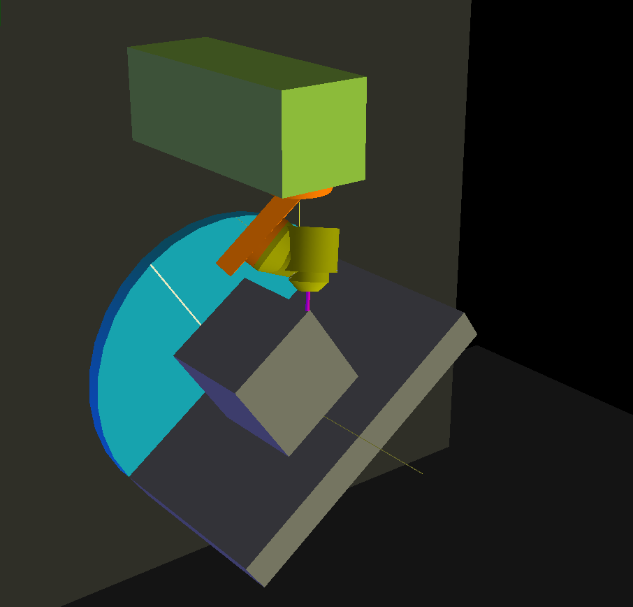
This is from work I've been doing to derive a kinematic model for a milling machine with a 45° nutating head like this one:
Notes:
1. TCP kinematic works
2. TOOL kinematics work also but there are some quirks that I have not been able to figure out. Like an odd behavior when issuing an incremental move immediately after switching to tool kinematics.
3. The attempted implementation of 'Tilted Work Plane' GCode is still rather experimental and would need a fair bit more work.
4. The config requires a custom vismach.py file for visualisation.
5. This kinematics requires version 2.10pre (ie master)
6. Documentation is included in the config folder as an html document.
Maybe somebody finds this useful
The zip folder below now contains two configs:
1. Table rotary C - spindle rotary B - spindle rotating (nutating 0..90°) A
2. Table rotary B - spindle rotary C - spindle rotating (nutating 0..90°) A
The spindle setup is defined in a [TWP] section in the ini file.
I have expanded the original config and documentation to a generic configuration with variable nutation angles 0-90°.
Also the Tilted Work Plane (TWP) section in the documentation has been expanded.
Note that that the TWP remap is still fairly experimental!
ORIGINAL POST:
This is from work I've been doing to derive a kinematic model for a milling machine with a 45° nutating head like this one:
Notes:
1. TCP kinematic works
2. TOOL kinematics work also but there are some quirks that I have not been able to figure out. Like an odd behavior when issuing an incremental move immediately after switching to tool kinematics.
3. The attempted implementation of 'Tilted Work Plane' GCode is still rather experimental and would need a fair bit more work.
4. The config requires a custom vismach.py file for visualisation.
5. This kinematics requires version 2.10pre (ie master)
6. Documentation is included in the config folder as an html document.
Maybe somebody finds this useful
Attachments:
Last edit: 21 Jan 2024 12:31 by Aciera. Reason: 3rd update
The following user(s) said Thank You: andypugh, grandixximo, danilom, tommylight, tivoi, rodw, besriworld, cakeslob, AndrewL
Please Log in or Create an account to join the conversation.
- grandixximo
-

- Away
- Elite Member
-

Less
More
- Posts: 266
- Thank you received: 337
27 Jun 2023 08:55 #274301
by grandixximo
Replied by grandixximo on topic Kinematic model for a 5axis mill with universal (45° nutating) head
This is coolest thing i've seen in a while, I'll have to study the configuration, congratulations man, looks amazing!
The following user(s) said Thank You: Aciera
Please Log in or Create an account to join the conversation.
- Aciera
-
Topic Author
- Offline
- Administrator
-
Less
More
- Posts: 4689
- Thank you received: 2097
27 Jun 2023 14:40 #274307
by Aciera
Replied by Aciera on topic Kinematic model for a 5axis mill with universal (45° nutating) head
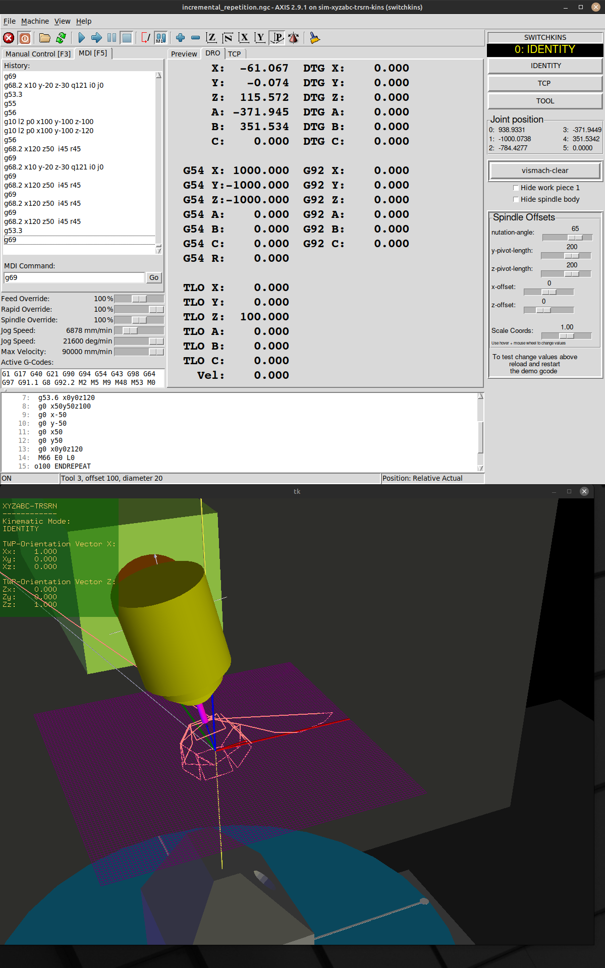
For a very quick demonstration of TCP/ TOOL kinematics:
github.com/Sigma1912/linuxcnc/assets/460...d6-b125-af95fb13b218
github.com/Sigma1912/linuxcnc/assets/460...d6-b125-af95fb13b218
Please Log in or Create an account to join the conversation.
- Aciera
-
Topic Author
- Offline
- Administrator
-
Less
More
- Posts: 4689
- Thank you received: 2097
27 Jun 2023 14:49 - 27 Jun 2023 15:10 #274308
by Aciera
Replied by Aciera on topic Kinematic model for a 5axis mill with universal (45° nutating) head
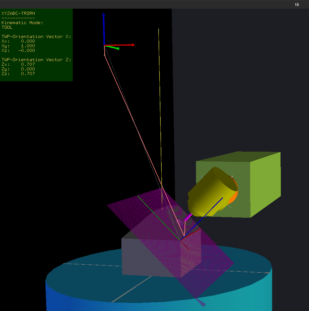
Here a quick demo of the Tilted Work Plane feature.
github.com/Sigma1912/linuxcnc/assets/460...38-8f23-50dc38e17c57
github.com/Sigma1912/linuxcnc/assets/460...38-8f23-50dc38e17c57
Last edit: 27 Jun 2023 15:10 by Aciera.
The following user(s) said Thank You: besriworld, Gurpreet
Please Log in or Create an account to join the conversation.
- Gurpreet
- Offline
- New Member
-

Less
More
- Posts: 8
- Thank you received: 1
18 Nov 2023 05:42 - 18 Nov 2023 05:43 #285796
by Gurpreet
Replied by Gurpreet on topic Kinematic model for a 5axis mill with universal (45° nutating) head
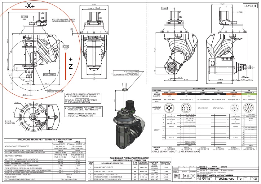
Hi, I'm trying to understand the matrix math to create the kinematics for 50 degree nutating spindle. It's a XYZAC with spindle rotating and nutating, fixed table machine.
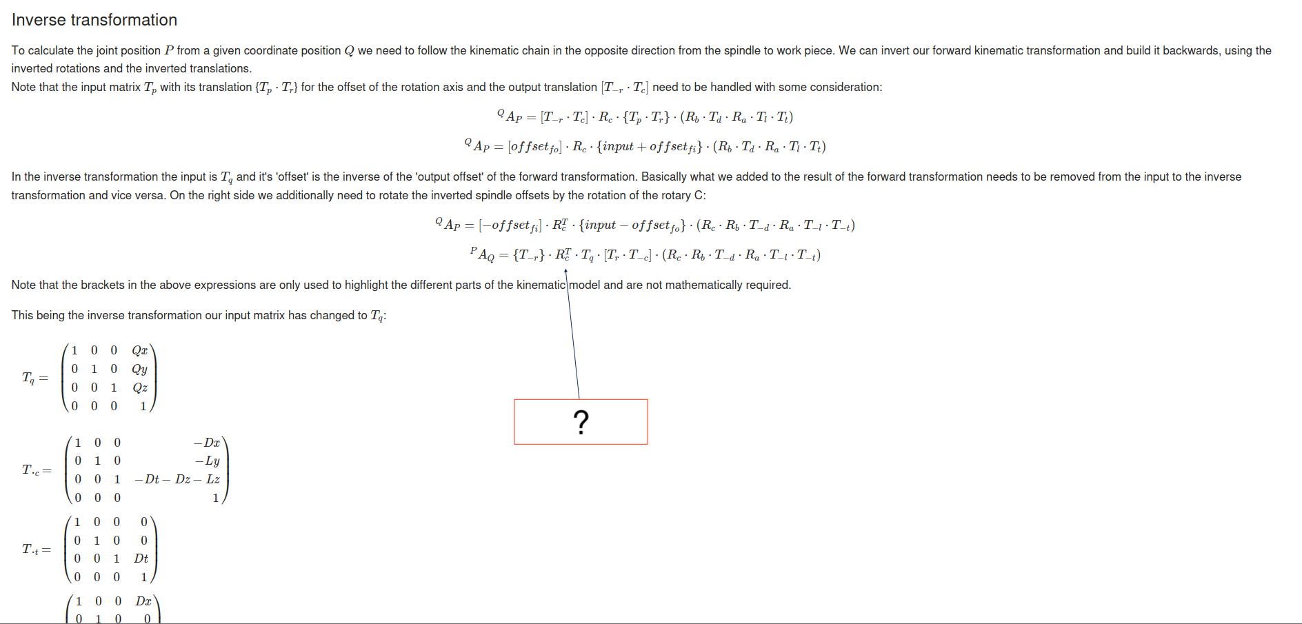
I'm following the manual found in the attachment. I'm stuck in the Inverse transformation section. Please see attached picture of the formula.
Could you please explain what that mean.
Thanks
I'm following the manual found in the attachment. I'm stuck in the Inverse transformation section. Please see attached picture of the formula.
Could you please explain what that mean.
Thanks
Attachments:
Last edit: 18 Nov 2023 05:43 by Gurpreet.
Please Log in or Create an account to join the conversation.
- Aciera
-
Topic Author
- Offline
- Administrator
-
Less
More
- Posts: 4689
- Thank you received: 2097
18 Nov 2023 07:03 #285798
by Aciera
Replied by Aciera on topic Kinematic model for a 5axis mill with universal (45° nutating) head
That would be the transpose of the rotation matrix for the table rotary C.
Since you have a fixed table and an AC spindle rotary assembly you would omit the C table rotation in my writeup and replace the B spindle rotation with a C spindle rotation (ie you would have 'Rc' instead of 'Rb' on the spindle side).
Also there is a typo in my write up: both of the lower two formulas are for inverse transformation (P_A_Q) and not just the last one.
The following user(s) said Thank You: Gurpreet
Please Log in or Create an account to join the conversation.
- grandixximo
-
- Away
- Elite Member
-
Less
More
- Posts: 266
- Thank you received: 337
18 Nov 2023 07:27 #285799
by grandixximo
Replied by grandixximo on topic Kinematic model for a 5axis mill with universal (45° nutating) head
From ChatGPT an explaination of teansposed matrix
Please Log in or Create an account to join the conversation.
- Gurpreet
- Offline
- New Member
-
Less
More
- Posts: 8
- Thank you received: 1
19 Nov 2023 01:54 - 19 Nov 2023 02:02 #285875
by Gurpreet
Replied by Gurpreet on topic Kinematic model for a 5axis mill with universal (45° nutating) head
Please see attached picture for the rotary head configuration.After removing the C axis from the table side and replacing B axis with C axis on the spindle side, C axis looking good in simulation, but only when Rotary A is at home position.After changing the angle of Rotary A, TCP start to create narrow oval.Do I have to change (Rotary A) transformation matrix as well.
Attachments:
Last edit: 19 Nov 2023 02:02 by Gurpreet.
Please Log in or Create an account to join the conversation.
- Aciera
-
Topic Author
- Offline
- Administrator
-
Less
More
- Posts: 4689
- Thank you received: 2097
19 Nov 2023 08:32 - 19 Nov 2023 08:42 #285881
by Aciera
Replied by Aciera on topic Kinematic model for a 5axis mill with universal (45° nutating) head
I can't read the numbers in the data sheet but if your nutation axis is not 45° then you would need to change the rotation matrix for A using the formula in my documentation.
I would suggest to start with the A axis (C = 0°) and work backwards. You will also need to think about which geometrical offsets are going to be relevant in your particular assembly.
[edit]
This section is where you will need to adjust for angles other than 45°.
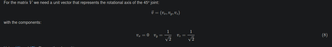
Note that in your case you may not be able to use a simple algebraic expression like 1 over the square root of two.
I would suggest to start with the A axis (C = 0°) and work backwards. You will also need to think about which geometrical offsets are going to be relevant in your particular assembly.
[edit]
This section is where you will need to adjust for angles other than 45°.
Note that in your case you may not be able to use a simple algebraic expression like 1 over the square root of two.
Attachments:
Last edit: 19 Nov 2023 08:42 by Aciera.
Please Log in or Create an account to join the conversation.
- grandixximo
-
- Away
- Elite Member
-
Less
More
- Posts: 266
- Thank you received: 337
20 Nov 2023 00:30 #285979
by grandixximo
Replied by grandixximo on topic Kinematic model for a 5axis mill with universal (45° nutating) head
He provided PDF that is readable at the end of the post, and the B axis is indeed at 50°
Please Log in or Create an account to join the conversation.
Time to create page: 1.081 seconds