Kinematic model for a 5axis mill with universal (nutating) head
- Aciera
-
 Topic Author
- Offline
- Administrator
-

Less
More
- Posts: 4724
- Thank you received: 2117
12 Jan 2024 06:27 #290472
by Aciera
Replied by Aciera on topic Kinematic model for a 5axis mill with universal (nutating) head
I'm a bit confused as to the arrangement of your table rotary, if it rotates in the XZ Plane then it would rotate around the Y-axis which would make it a B-rotary and not an A-rotary.
Also looking at your vismach model I see the machine coordinates pointing with the y-axis (green arrow) along the axis of your table rotary.
I presume the issues you describe are observed on the vismach model and not on the real machine.
Does the TCP mode work as expected?
Does the jogging work along the tool-z axis when in TOOL mode?
As a general note:
There are really two different models to set up here, one being the kinematic model as described in the documentation and the other being the vismach model seen on the screen.
As a consequence if you see unexpected behavior the problem may be and error in the kinematic model or it may be in the vismach model or both.
Please Log in or Create an account to join the conversation.
- Paul01
-

- Offline
- Junior Member
-

Less
More
- Posts: 25
- Thank you received: 5
12 Jan 2024 08:01 #290477
by Paul01
Replied by Paul01 on topic Kinematic model for a 5axis mill with universal (nutating) head
Maybe I was a little unclear in my description. How it's shown in the image is correct. The B rotary table rotates around the Y axis (green arrow). The nutating A,C head has the nutating A joint rotating around the X axis (red arrow). However, because it's nutating, I said the A axis lies on the XZ plane.
Based on your original config, I've implemented both TCP and TOOL kinematics on my real machine and they behave correctly/the same on my real machine and in Vismach. I do understand what you mean about the difference between the kinematics and the Vismach model. I saw this initially with my real machines C axis rotating the opposite of my Vismach model. And it's pretty obvious something is wrong when in TCP mode.
Then based on your updated config (and because it's very similar to my real machine), I went through the Juypter file and redid the kinematics to set up a simulation machine in order to get the TWPs working. The kinematics seem to work correctly. Both TCP and TOOL work as expected in Vismach. And it does correctly jog along the tool-Z axis in TOOL mode. After working through your original config and implementing the kinematics on my real machine, I think I have an ok understanding of Vismach, the kinematics, and their relation to my real machine.
With all that said, my math skills are lacking. And I'm not sure if what I have done is correct when it comes to rearranging the equations I need to get the tilted work planes working. I posted what I have done in my previous post. Any help would be appreciated as I'm sure what I have done is wrong.
Please Log in or Create an account to join the conversation.
- Aciera
-
Topic Author
- Offline
- Administrator
-
Less
More
- Posts: 4724
- Thank you received: 2117
12 Jan 2024 08:30 #290481
by Aciera
Replied by Aciera on topic Kinematic model for a 5axis mill with universal (nutating) head
Ok, good.
Next question:
The tool vectors 'Kz = (Kzx, Kzy, Kzz)' and 'Kx=(Kxx, Kxy, Kxz)' you use in the TWP-angle-calculations you posted are those from the transformation matrix you use in the 'Inverse TOOL kinematics' ?
Next question:
The tool vectors 'Kz = (Kzx, Kzy, Kzz)' and 'Kx=(Kxx, Kxy, Kxz)' you use in the TWP-angle-calculations you posted are those from the transformation matrix you use in the 'Inverse TOOL kinematics' ?
Please Log in or Create an account to join the conversation.
- Paul01
-
- Offline
- Junior Member
-
Less
More
- Posts: 25
- Thank you received: 5
12 Jan 2024 09:17 #290484
by Paul01
Replied by Paul01 on topic Kinematic model for a 5axis mill with universal (nutating) head
Yes they are. From the Inverse Tool kinematics I've taken the third column to calculate the spindle rotary joint positions for the tool orientation vector, and then taken the first column for the Tool-X vector.
Please Log in or Create an account to join the conversation.
- Aciera
-
Topic Author
- Offline
- Administrator
-
Less
More
- Posts: 4724
- Thank you received: 2117
12 Jan 2024 09:46 #290486
by Aciera
Replied by Aciera on topic Kinematic model for a 5axis mill with universal (nutating) head
can you post your remap.py please?
Please Log in or Create an account to join the conversation.
- Paul01
-
- Offline
- Junior Member
-
Less
More
- Posts: 25
- Thank you received: 5
12 Jan 2024 10:02 #290488
by Paul01
Replied by Paul01 on topic Kinematic model for a 5axis mill with universal (nutating) head
Remap attached
Please Log in or Create an account to join the conversation.
- Aciera
-
Topic Author
- Offline
- Administrator
-
Less
More
- Posts: 4724
- Thank you received: 2117
12 Jan 2024 15:38 #290506
by Aciera
Replied by Aciera on topic Kinematic model for a 5axis mill with universal (nutating) head
Likely a problem with the quadrant handling so get going change lines 64 and 65 like this:
And see what you get. Don't worry about the tool-x vector until you get the tool-z orientation worked out.
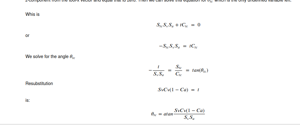
Also I think you have an error in the calculation of angle 'tc', here is what I get:
Just out of curiosity, it this for a home built machine or a retrofit of a commercial one?
    if True: #Kwx >= 0:
        if True: #Kwy >= 0:
            A_j = acos((Kwz-Cv*Cv)/(1-Cv*Cv))
            Sa_j  = sin(A_j)
            Ca_j  = cos(A_j)
            t = Sv*Cv*(1-Ca_j)
            p = Sv * Sa_j
            C_j = acos((t*Kwx-p*Kwy)/(p*p+t*t))
            print('C_j new: ', C_j*180/pi)
            quad = 111 #Done
And see what you get. Don't worry about the tool-x vector until you get the tool-z orientation worked out.
Also I think you have an error in the calculation of angle 'tc', here is what I get:
Just out of curiosity, it this for a home built machine or a retrofit of a commercial one?
Attachments:
Please Log in or Create an account to join the conversation.
- Aciera
-
Topic Author
- Offline
- Administrator
-
Less
More
- Posts: 4724
- Thank you received: 2117
12 Jan 2024 18:32 - 12 Jan 2024 18:34 #290521
by Aciera
Replied by Aciera on topic Kinematic model for a 5axis mill with universal (nutating) head
I've modified a sim config to reflect your situation. It's still a bit messy but I have run out of time for now.
Note the changed remap structure and how the python remap is being called from other ngc remaps. This gets rid of a bug where sometimes the spindle orientation would send the machine to some strange places. It looks quite solid now. I would very much recommend using this structure for use on a real machine.
Also there is a 'twp-helper-component' that is used as an intermediary between the remap and the gui.
Hope this helps.
Attachments:
Last edit: 12 Jan 2024 18:34 by Aciera.
Please Log in or Create an account to join the conversation.
- Paul01
-
- Offline
- Junior Member
-
Less
More
- Posts: 25
- Thank you received: 5
12 Jan 2024 20:50 - 12 Jan 2024 23:16 #290530
by Paul01
Replied by Paul01 on topic Kinematic model for a 5axis mill with universal (nutating) head
Amazing! Thank you so much. Changing to if True worked. I was really unsure how to rearrange the equation for angle 'tc', but what you've posted works too.
I'll go through your modified sim config and use that instead of what I've done. And with it I should have my machine properly up and running.
So this is for a home built machine. I use a Biesse Rover B at my job, and wanted something similar to use at home for myself. It's about what you'd expect for a home built machine and isn't at the level of a commercial machine. But my 2 axis head is loosely based on the HSD nutating head found on the Biesse CNC. Being very ignorant to the kinematics required at the time of designing and building it, I decided to go with a similar style of nutating head. I think that without finding the work you've posted in this thread I would have had a difficult time getting my machine up and running. And I've found the Jupyter file extremely invaluable. So I'm very grateful for the work you've put into these sim configs.
I work in furniture manufacturing, and a lot of what I do on a CNC involves pretty basic 2D toolpaths, often on angled faces. And because of the advantages TWPs offer, I'll be pretty happy to get that side of things up and running. And in the future when I have my machine fully working I'll post some of my stuff on this forum. The last thing I have to do to finish off my real machine is to purchase all the required hardware for the rotary table. Currently that's just something that I have working on my sim config, but I wanted to make sure I had everything sorted in my config so the addition of a B rotary unit would be easy.
Last edit: 12 Jan 2024 23:16 by Paul01.
Please Log in or Create an account to join the conversation.
- Paul01
-
- Offline
- Junior Member
-
Less
More
- Posts: 25
- Thank you received: 5
13 Jan 2024 01:31 #290540
by Paul01
Replied by Paul01 on topic Kinematic model for a 5axis mill with universal (nutating) head
I've now gone through your modified sim config and got that working on my end too. Now I just need to build the Vismach model of my actual machine and then implement everything in the real world.
One thing I'm curious about with Vismach. It would be cool if it could display custom cutters when calling for a tool in your NC file. So if you're using something other than an end mill, Vismach could display an .obj from a folder of custom cutters and set it to the correct tool_length. Not sure if it's possible, but it would be useful for visual confirmation, especially if you're also importing your work_piece into Vismach.
One thing I'm curious about with Vismach. It would be cool if it could display custom cutters when calling for a tool in your NC file. So if you're using something other than an end mill, Vismach could display an .obj from a folder of custom cutters and set it to the correct tool_length. Not sure if it's possible, but it would be useful for visual confirmation, especially if you're also importing your work_piece into Vismach.
Please Log in or Create an account to join the conversation.
Time to create page: 0.202 seconds