Kinematic model for a 5axis mill with universal (nutating) head
- Paul01
-

- Offline
- Junior Member
-

- Posts: 25
- Thank you received: 5
# returns the A/B joint positions for a given tool-orientation vector
# kinematics specific
def kins_calc_jnt_angles(self, tool_z_req):
epsilon = 0.000001
print("Vector tool-z-requested",tool_z_req)
# using xyzabc-trsrn-og kinematics (ALL ANGLES ARE IN RADIANS)
(Kwx, Kwy, Kwz) = (tool_z_req[0], tool_z_req[1], tool_z_req[2])
# in this particular kinematic there are infinite solutions for tool_z vector =[0,1,0]
# so we need to check if the requested tool_z vector is sufficiently close to it
if Kwy > 1 - epsilon:
A_j = pi # note: we can choose the rotation direction of the joint with the sign (+/-pi)
B_j = 0
return(A_j, B_j)
# note: handling of individual quadrants is required
if Kwx >= 0:
A_j = pi - acos(2*Kwy - 1)
Sa_j = sin(A_j)
Ca_j = cos(A_j)
if Kwz >= 0:
if -(sqrt(2)*Kwz*Sa_j) <= Sa_j*Sa_j:
B_j = (- asin(2*(sqrt(2)*Kwz*Sa_j - (Ca_j + 1)*Kwx)/(Ca_j*Ca_j
+ 2*Sa_j*Sa_j + 2*Ca_j + 1)))
quad = 111
else: # Kwz < 0 AND Kwz < 0
B_j = (pi + asin(2*(sqrt(2)*Kwz*Sa_j - (Ca_j + 1)*Kwx)/(Ca_j*Ca_j
+ 2*Sa_j*Sa_j + 2*Ca_j + 1)))
quad = 112
else: # Kwz < 0
if -(sqrt(2)*Kwz*Sa_j) <= Sa_j*Sa_j:
B_j = (pi/2 - asin(2*(sqrt(2)*Kwz*Sa_j - (Ca_j + 1)*Kwx)/(Ca_j*Ca_j
+ 2*Sa_j*Sa_j + 2*Ca_j + 1)))
quad = 121
else: # Kwz < 0 AND Kwz < 0
B_j = (pi - asin(2*(sqrt(2)*Kwz*Sa_j - (Ca_j + 1)*Kwx)/(Ca_j*Ca_j
+ 2*Sa_j*Sa_j + 2*Ca_j + 1)))
quad = 122
else: # Kwx < 0
A_j = - pi + acos(2*Kwy - 1);
Sa_j = sin(A_j);
Ca_j = cos(A_j);
if Kwz >= 0:
if sqrt(2)*Kwz*Sa_j <= Sa_j*Sa_j:
B_j = (- asin(2*(sqrt(2)*Kwz*Sa_j - (Ca_j + 1)*Kwx)/(Ca_j*Ca_j
+ 2*Sa_j*Sa_j + 2*Ca_j + 1)))
quad = 211
else:
B_j = (- pi + asin(2*(sqrt(2)*Kwz*Sa_j - (Ca_j + 1)*Kwx)/(Ca_j*Ca_j
+ 2*Sa_j*Sa_j + 2*Ca_j + 1)))
quad = 212
else:
if sqrt(2)*Kwz*Sa_j <= Sa_j*Sa_j:
B_j = (-pi/2 - asin(2*(sqrt(2)*Kwz*Sa_j - (Ca_j + 1)*Kwx)/(Ca_j*Ca_j
+ 2*Sa_j*Sa_j + 2*Ca_j + 1)))
quad = 221
else:
B_j = (- pi + asin(2*(sqrt(2)*Kwz*Sa_j - (Ca_j + 1)*Kwx)/(Ca_j*Ca_j
+ 2*Sa_j*Sa_j + 2*Ca_j + 1)))
quad = 222
#if Kwz < 0:
# B_j = -B_j
# return(A_j, B_j)
print("QUADRANT: ",quad)
# return angles in radians
return(A_j, B_j)
Please Log in or Create an account to join the conversation.
- Aciera
-
 Topic Author
- Offline
- Administrator
-

- Posts: 4714
- Thank you received: 2107
A_j = acos(2*Kwy - 1)
Sa_j = sin(A_j)
Ca_j = cos(A_j)
B_j = asin(2*(sqrt(2)*Kwz*Sa_j - (Ca_j + 1)*Kwx)/(Ca_j*Ca_j + 2*Sa_j*Sa_j + 2*Ca_j + 1))
If you plug that into the remap and test the simulation you will notice that there are ranges of tool-orientations where the resulting angles are offset to what you need to get the spindle correctly oriented. In some ranges it will fit in others it is the complement of what you need or the you need to change the sign of the value. These 'areas' is what I call 'quadrants' in the remap. A lot of this came through trial and error along the lines of 'from here to here need to add 'pi' and from there to there I need to subtract half a pi and change the sign'.
Unfortunately I don't recall how I came up with the conditionals:
if sqrt(2)*Kwz*Sa_j <= Sa_j*Sa_j:
I'll see if that comes back to me.
Here is a somewhat expanded, later version:
# returns the A/B joint positions for a given tool-orientation vector
# NOTE: These formulas are specific to the machine
def kins_calc_jnt_angles(self, tool_z_req):
    epsilon = 0.000001
    print("Vector tool-z-requested",tool_z_req)
    # using xyzabc-trsrn kinematics (ALL ANGLES ARE IN RADIANS)
    (Kwx, Kwy, Kwz) = (tool_z_req[0], tool_z_req[1], tool_z_req[2])

    # on this particular machine the tool cannot be oriented if the requested tool-z vector
    # has a negative y-component (ie Kwy)
    if Kwz > 1 - epsilon:
        return (0 ,0)

    elif Kwy < 0:
        print("Error -> Tool-z-requested is outside of this kinematic, aborting 'kins_calc_jnt_angles()'")
        return(None, None)

    # in this particular kinematic there are infinite solutions for tool_z vector =[0,1,0]
    # so we need to check if the requested tool_z vector is sufficiently close to it
    elif Kwx > 1 - epsilon:
        A_j = 0
        B_j = pi/2
        return(A_j, B_j)

    elif Kwx < -1 + epsilon:
        A_j = 0
        B_j = -pi/2
        return(A_j, B_j)

    elif Kwy > 1 - epsilon:
        A_j = pi  # note: we can choose the rotation direction of the joint with the sign (+/-pi)
        B_j = 0
        return(A_j, B_j)

    elif Kwz < -1 + epsilon:
        A_j = 0
        B_j = pi  # note: we can choose the rotation direction of the joint with the sign (+/-pi)
        return(A_j, B_j)

    # note: handling of individual quadrants is required
    if Kwx >= 0:
        A_j = pi - acos(2*Kwy - 1)
        Sa_j  = sin(A_j)
        Ca_j  = cos(A_j)
        if Kwz >= 0:
            if  -(sqrt(2)*Kwz*Sa_j) <= Sa_j*Sa_j:
                B_j = (- asin(2*(sqrt(2)*Kwz*Sa_j - (Ca_j + 1)*Kwx)/(Ca_j*Ca_j
                       + 2*Sa_j*Sa_j + 2*Ca_j + 1)))
                quad = 111
            else: # Kwz <  0 AND Kwz < 0
                B_j = (pi + asin(2*(sqrt(2)*Kwz*Sa_j - (Ca_j + 1)*Kwx)/(Ca_j*Ca_j
                       + 2*Sa_j*Sa_j + 2*Ca_j + 1)))
                quad = 112
        else: # Kwz < 0
            A_j =  pi + acos(2*Kwy - 1);
            Sa_j  = sin(A_j);
            Ca_j  = cos(A_j);
            if  -(sqrt(2)*Kwz*Sa_j) <= Sa_j*Sa_j:
                B_j = (pi + asin(2*(sqrt(2)*Kwz*Sa_j - (Ca_j + 1)*Kwx)/(Ca_j*Ca_j
                       + 2*Sa_j*Sa_j + 2*Ca_j + 1)))
                quad = 121
            else: # Kwz <  0 AND Kwz < 0
                B_j = (pi - asin(2*(sqrt(2)*Kwz*Sa_j - (Ca_j + 1)*Kwx)/(Ca_j*Ca_j
                       + 2*Sa_j*Sa_j + 2*Ca_j + 1)))
                quad = 122

    else: # Kwx < 0
        A_j = - pi + acos(2*Kwy - 1);
        Sa_j  = sin(A_j);
        Ca_j  = cos(A_j);
        if Kwz >= 0:
            if sqrt(2)*Kwz*Sa_j <= Sa_j*Sa_j:
                B_j = (- asin(2*(sqrt(2)*Kwz*Sa_j - (Ca_j + 1)*Kwx)/(Ca_j*Ca_j
                       + 2*Sa_j*Sa_j + 2*Ca_j + 1)))
                quad = 211
            else:
                B_j = (- pi + asin(2*(sqrt(2)*Kwz*Sa_j - (Ca_j + 1)*Kwx)/(Ca_j*Ca_j
                       + 2*Sa_j*Sa_j + 2*Ca_j + 1)))
                quad = 212
        else:
            A_j = - pi - acos(2*Kwy - 1);
            Sa_j  = sin(A_j);
            Ca_j  = cos(A_j);
            if sqrt(2)*Kwz*Sa_j <= Sa_j*Sa_j:
                B_j = (-pi + asin(2*(sqrt(2)*Kwz*Sa_j - (Ca_j + 1)*Kwx)/(Ca_j*Ca_j
                       + 2*Sa_j*Sa_j + 2*Ca_j + 1)))
                quad = 221
            else:
                B_j = (- pi + asin(2*(sqrt(2)*Kwz*Sa_j - (Ca_j + 1)*Kwx)/(Ca_j*Ca_j
                       + 2*Sa_j*Sa_j + 2*Ca_j + 1)))
                quad = 222
    #if Kwz < 0:
    #    B_j = -B_j
    #    return(A_j, B_j)


    print("QUADRANT: ",quad)
    # return angles in radians
    return(A_j, B_j)
NB: clearly some of the comments in the code make no sense. Like this one:
# Kwz < 0 AND Kwz < 0
These are a remnant of the stage where I thought I could keep the quadrants apart by checking whether individual elements of the tool-vector were positive or negative. Alas it's not quite so simple.
Please Log in or Create an account to join the conversation.
- Aciera
-
Topic Author
- Offline
- Administrator
-
- Posts: 4714
- Thank you received: 2107
I've had some time to look at this again and it seems that this condition is always true.Unfortunately I don't recall how I came up with the conditionals:
if sqrt(2)*Kwz*Sa_j <= Sa_j*Sa_j:
So maybe try to simply remove those and also the formulas for 'quadrants' 112,122,212 and 222
Please Log in or Create an account to join the conversation.
- Paul01
-
- Offline
- Junior Member
-
- Posts: 25
- Thank you received: 5
It's been a steep learning curve jumping into 5 axis kinematics. Until a month or two ago my machine was only a 3 axis. So it'll take me a bit of time to implement everything correctly.
As a side note, a large portion of the programming I do on the 5 axis machines at my work is just 2D machining on angled faces, so I'm glad TWP's are being worked on in LinuxCNC.
I wonder also if Fusion 360's post can convert tilted work plane operations to XYZABC coordinates and keep the original work coordinate system. This will help me out while I'm working through the 'remap.py' file
Please Log in or Create an account to join the conversation.
- Aciera
-
Topic Author
- Offline
- Administrator
-
- Posts: 4714
- Thank you received: 2107
I really don't know much about 5axis machining. The machines I have worked on only had manual swivel heads. However TWP has already proved useful even for that, if only in it's most basic form.
Keep in mind that, on a real machine, consideration needs to be given to the conditioning of the angular values as calculated in the remap since real joints may not be able to turn 360°. I've only made a crude attempt at this.
Implementing, a much simplified version of TWP, has shown that a fair bit of work needs to be invested to make this as user friendly as possible. Mainly properly resetting the controller after an abort while TWP is active needs to be considered.
Since I posted the config, I have removed the TWP offset from the kinematic and included its handling in the remap (mostly). This avoids offsetting G53 (absolute machine coordinate moves) by TWP offset values when TWP is active.
Also, I have invested a lot of work in making the preview aware of TWP and the calculation of limit violations using the preview data.
Please Log in or Create an account to join the conversation.
- JacobRush
- Offline
- Junior Member
-
- Posts: 24
- Thank you received: 2
Also It will prevent you from calling a G18, G19 etc tool plane while a G7 work plane rotation is active.
Please Log in or Create an account to join the conversation.
- Aciera
-
Topic Author
- Offline
- Administrator
-
- Posts: 4714
- Thank you received: 2107
forum.linuxcnc.org/show-your-stuff/49103...-head?start=0#271334
Also It will prevent you from calling a G18, G19 etc tool plane while a G7 work plane rotation is active.
This is a somewhat weak point of using python remaps to introduce new Gcode as Linuxcnc really has no idea about the new functionality and so we cannot keep the operator from using any Gcodes that may not be compatible with our functionality. All we could do is have a helper component monitoring the python status channel and abort in case of a conflict.
On the other hand if we have an error while executing gcode with TWP active then Linuxcnc will revert to G54 and we will need to deal with things in a custom 'on_abort' file.
Anybody who wants to implement this on a real machine is going to have to spend a lot of thought to avoid 'awkward ' situations. The way it is is really just fit for a simulation configuration.
Please Log in or Create an account to join the conversation.
- Paul01
-
- Offline
- Junior Member
-
- Posts: 25
- Thank you received: 5
Please Log in or Create an account to join the conversation.
- Aciera
-
Topic Author
- Offline
- Administrator
-
- Posts: 4714
- Thank you received: 2107
Attachments:
Please Log in or Create an account to join the conversation.
- Paul01
-
- Offline
- Junior Member
-
- Posts: 25
- Thank you received: 5
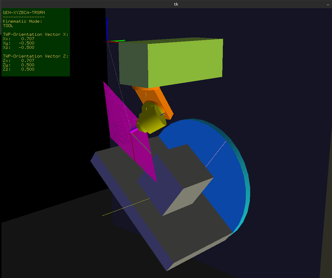
I have my machine running based on your original post. Now I'm going back to implement TWP's, so I'm using your updated generic-xyzbca files. The only difference is that my A axis is on the XZ plane not the YZ plane. See image attached for reference.
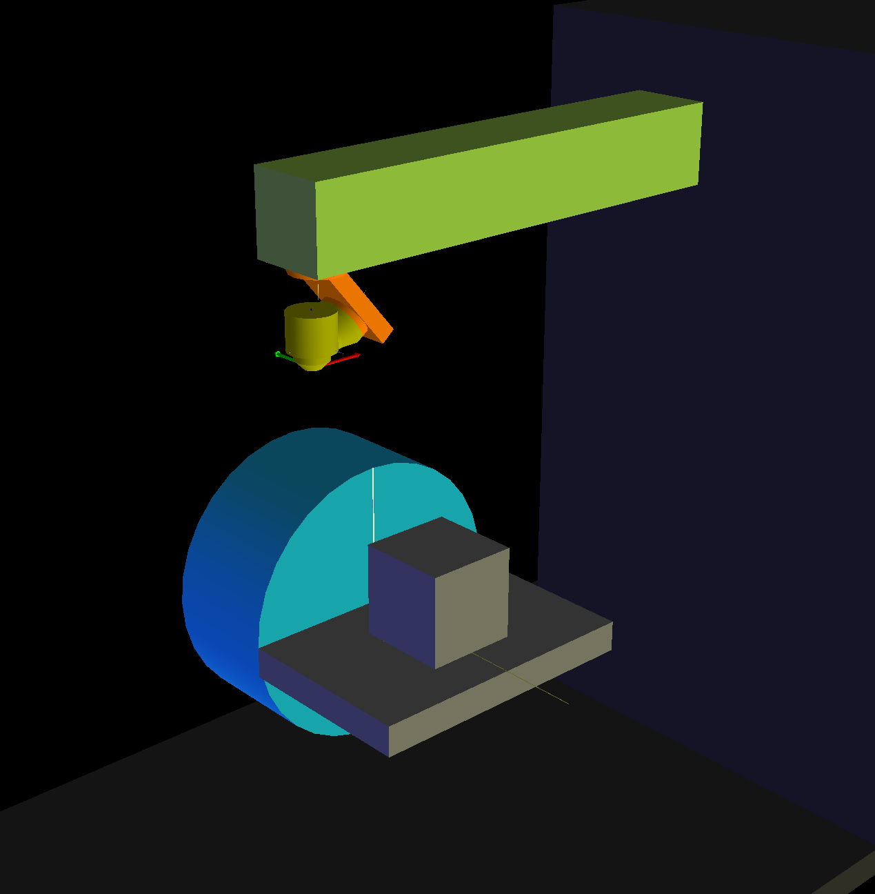
Other than a different rotation matrix for A (and Lx instead of Ly), it's much the same as your files. The r, s, t values are also the same.
However, I've clearly done something wrong in my TWP maths as I'm not getting the correct results, so some help would be much appreciated.
This is what I have for the rotary joints. The C axis generally doesn't rotate correctly to the TWP.
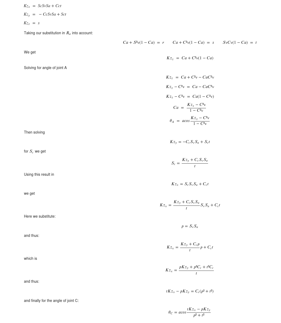
And this is what I have for the Tool-X vector. Also no behaving correctly.
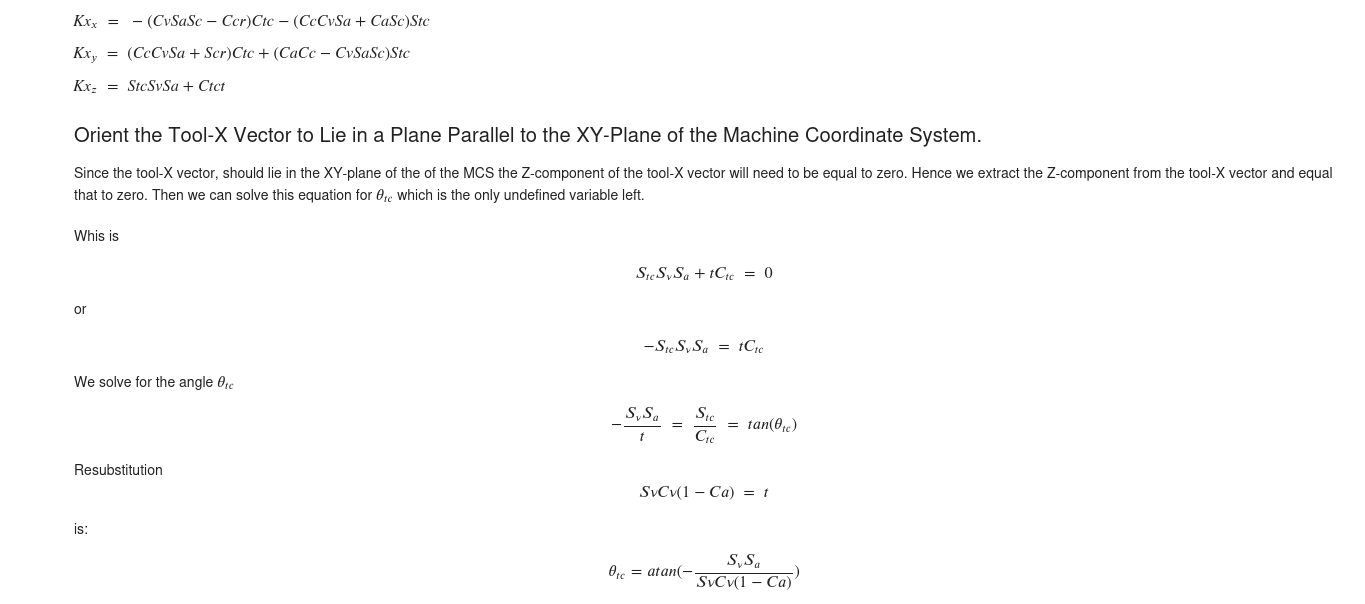
I'm not great with maths so this is a little beyond my expertise.
Attachments:
Please Log in or Create an account to join the conversation.