
Optimum Optimill MH50V CNC conversion
- dbtayl
- Offline
- Senior Member
-

Less
More
- Posts: 48
- Thank you received: 46
21 Sep 2026 15:52 #349765
by dbtayl
Replied by dbtayl on topic Optimum Optimill MH50V CNC conversion
I don't usually clutter up threads like this just to say it looks great, but... looks great! I still need to get the spindle motor cooling shroud finished and installed on my machine... really easy to leave things unfinished once you can make chips, so good on you.
The following user(s) said Thank You: Unlogic
Please Log in or Create an account to join the conversation.
- Unlogic
- Offline
- Elite Member
-

Less
More
- Posts: 257
- Thank you received: 128
24 Sep 2026 17:56 #349843
by Unlogic
Replied by Unlogic on topic Optimum Optimill MH50V CNC conversion
Thanks for the feedback dbtayl. Don't worry about clutter, forum threads like this are all about dialog and sharing experiences.
For some reason the final bits always take longer than expected to get sorted. I've managed to get the spindle liquid cooling installed and to somewhat button up the build for now.
The first challenge with the spindle cooling was the location of the inlet which is located at the back of the spindle flange.
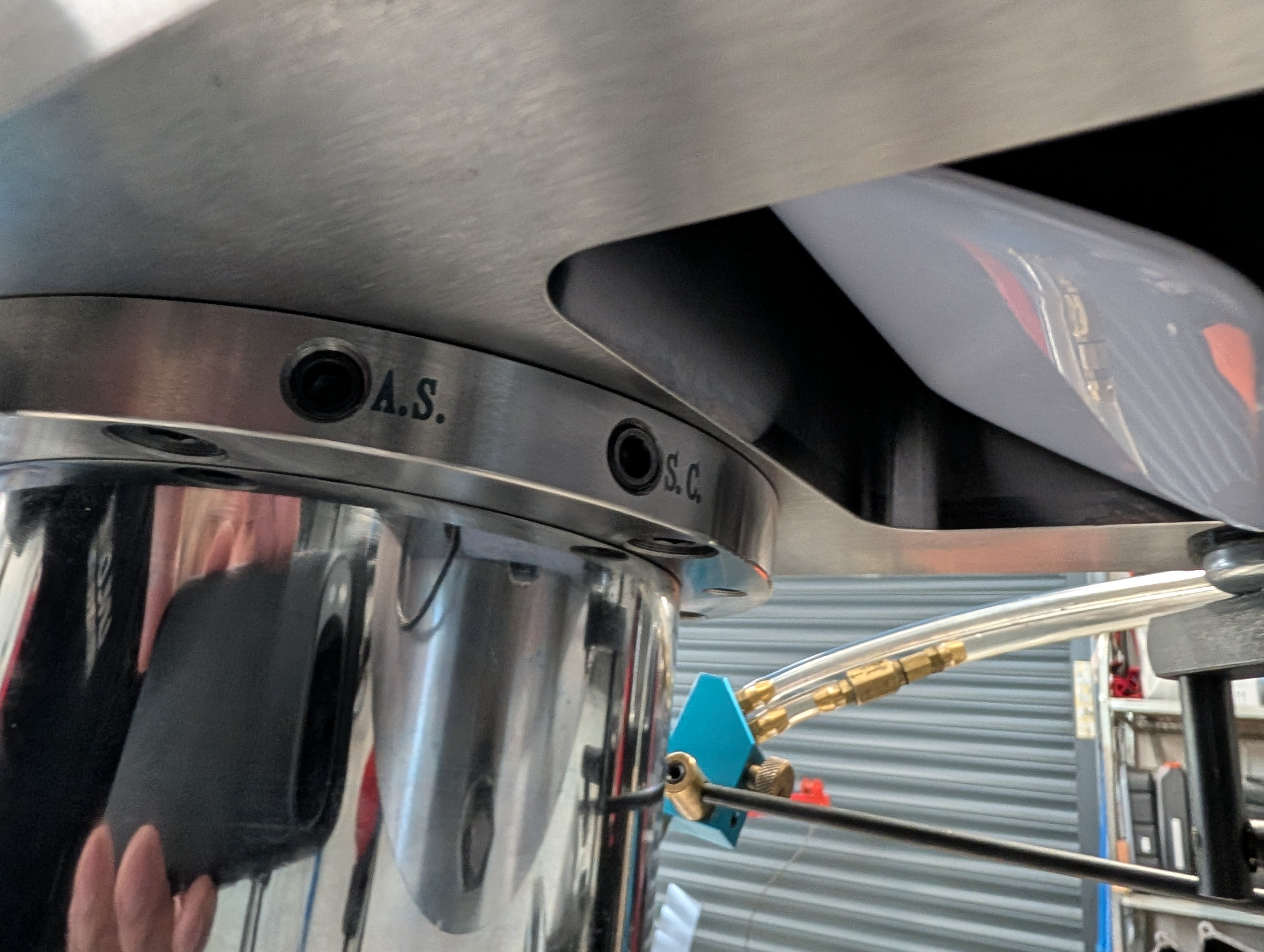
I didn't want any hoses down there as the hot chips when milling steel could easily damage them. So I did a little workaround using an angled fitting and a bit of pipe originally meant for a grease based central lubrication system.
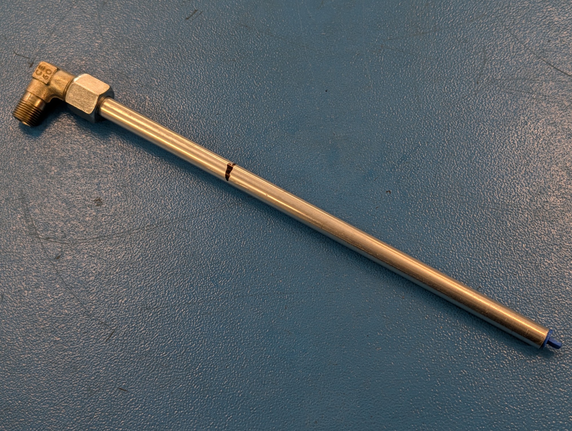
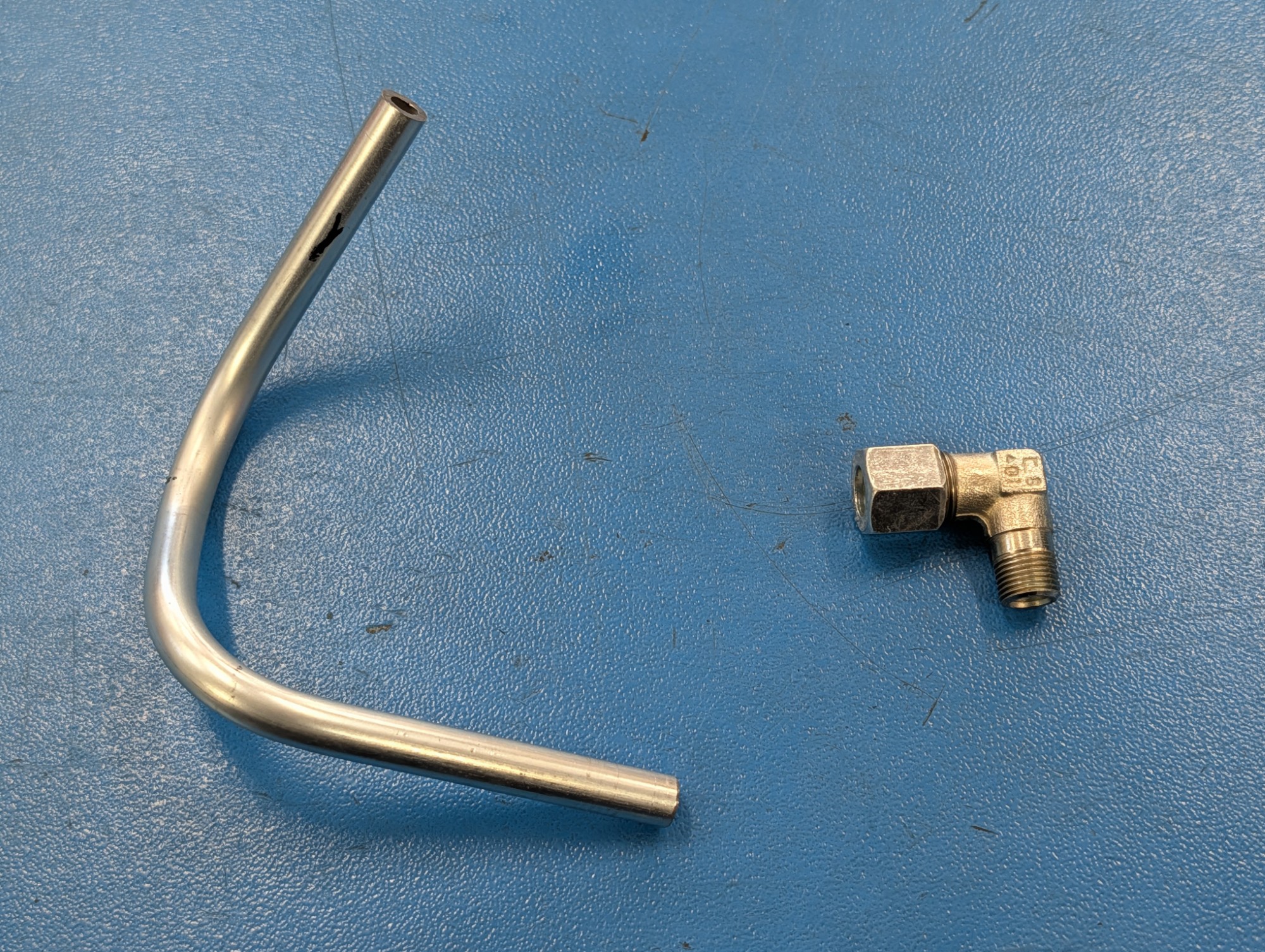
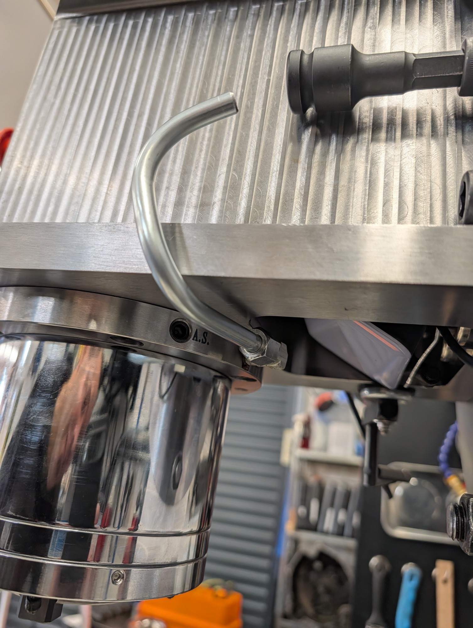
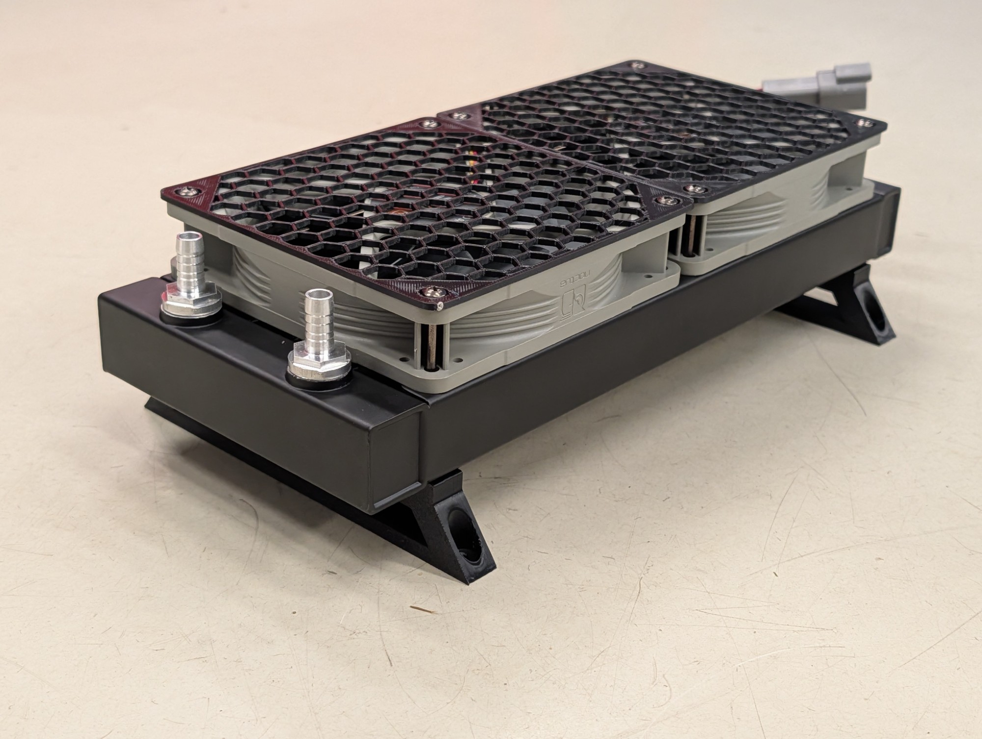
Next up I tackled the the cheap PC water cooling radiator I had purchased of Amazon. I 3D printed some wall mounts for it along with two fan grills for the Noctua fans.
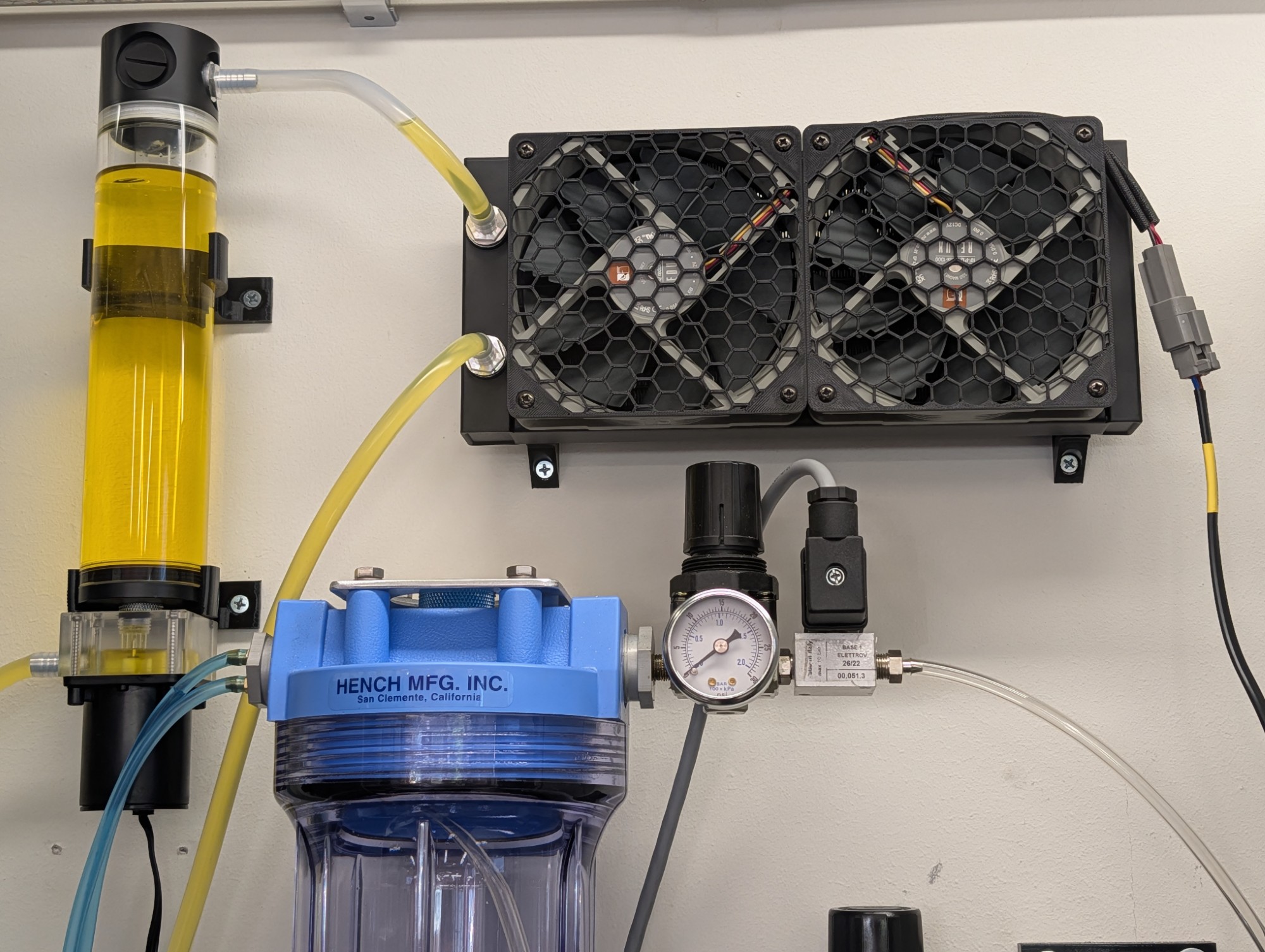
Here it is mounted on the wall together with the pump/reservoir unit which I also purchased of Amazon. The yellow color is from the special type of antifreeze I use together with deionized water.
For some reason the final bits always take longer than expected to get sorted. I've managed to get the spindle liquid cooling installed and to somewhat button up the build for now.
The first challenge with the spindle cooling was the location of the inlet which is located at the back of the spindle flange.
I didn't want any hoses down there as the hot chips when milling steel could easily damage them. So I did a little workaround using an angled fitting and a bit of pipe originally meant for a grease based central lubrication system.
Next up I tackled the the cheap PC water cooling radiator I had purchased of Amazon. I 3D printed some wall mounts for it along with two fan grills for the Noctua fans.
Here it is mounted on the wall together with the pump/reservoir unit which I also purchased of Amazon. The yellow color is from the special type of antifreeze I use together with deionized water.
Attachments:
Please Log in or Create an account to join the conversation.
- Unlogic
- Offline
- Elite Member
-
Less
More
- Posts: 257
- Thank you received: 128
24 Sep 2026 18:03 #349844
by Unlogic
Replied by Unlogic on topic Optimum Optimill MH50V CNC conversion
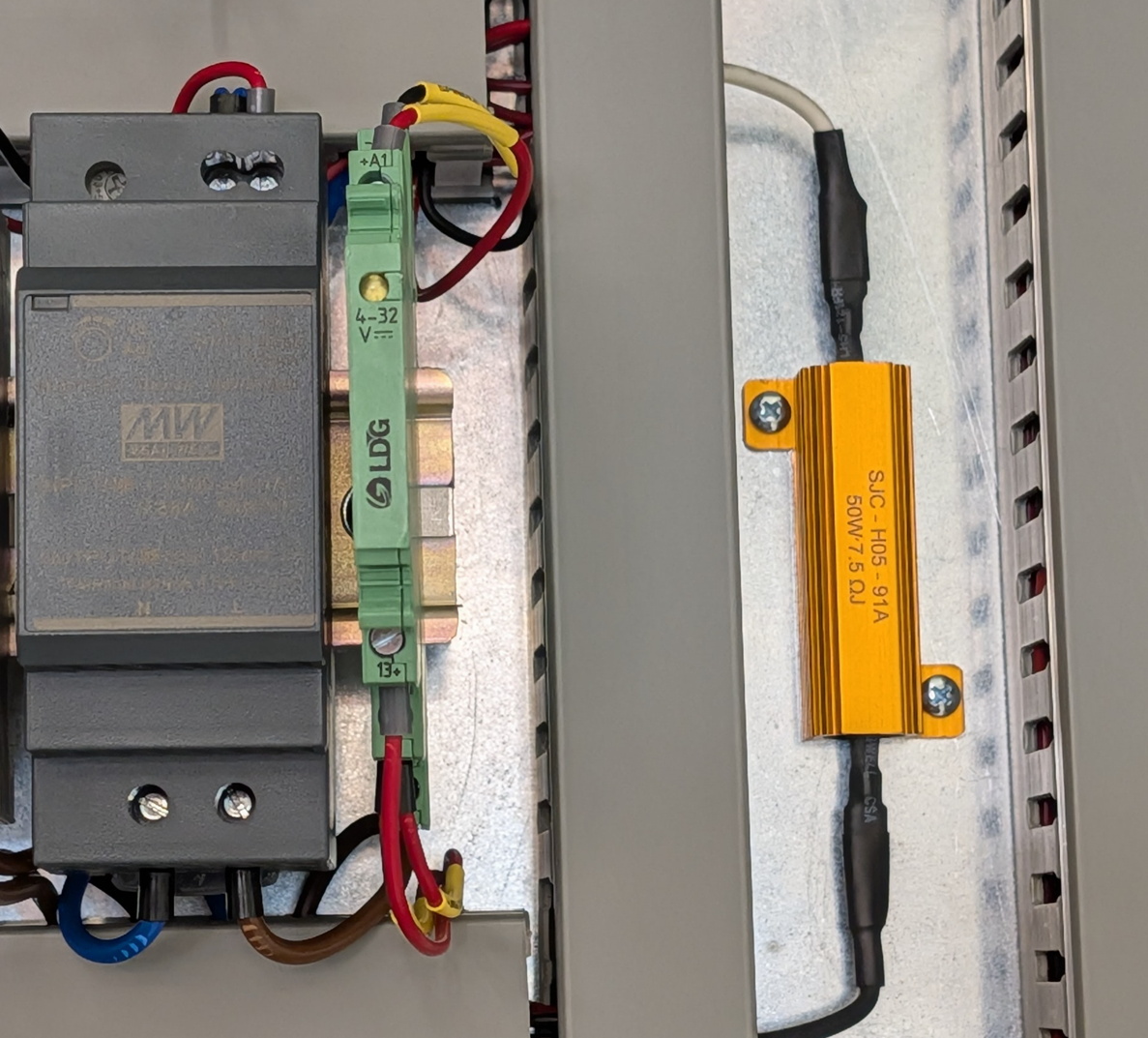
Since the both the pump and fans are meant to be used in PC's they are rated for 12 volts so I added a separate Meanwell 12V/2A power supply for them.
The power supply is constantly powered but I switch the output side using a solid state relay so that the cooling only runs when the spindle is on.
However the pump proved to be a bit noisy and way too powerful give the small diameter hose I'm running. So added a 7.5Ω resistor in series with the pump to bring the voltage down to 8V which made it much quieter and brought the flow down to a more suitable level.
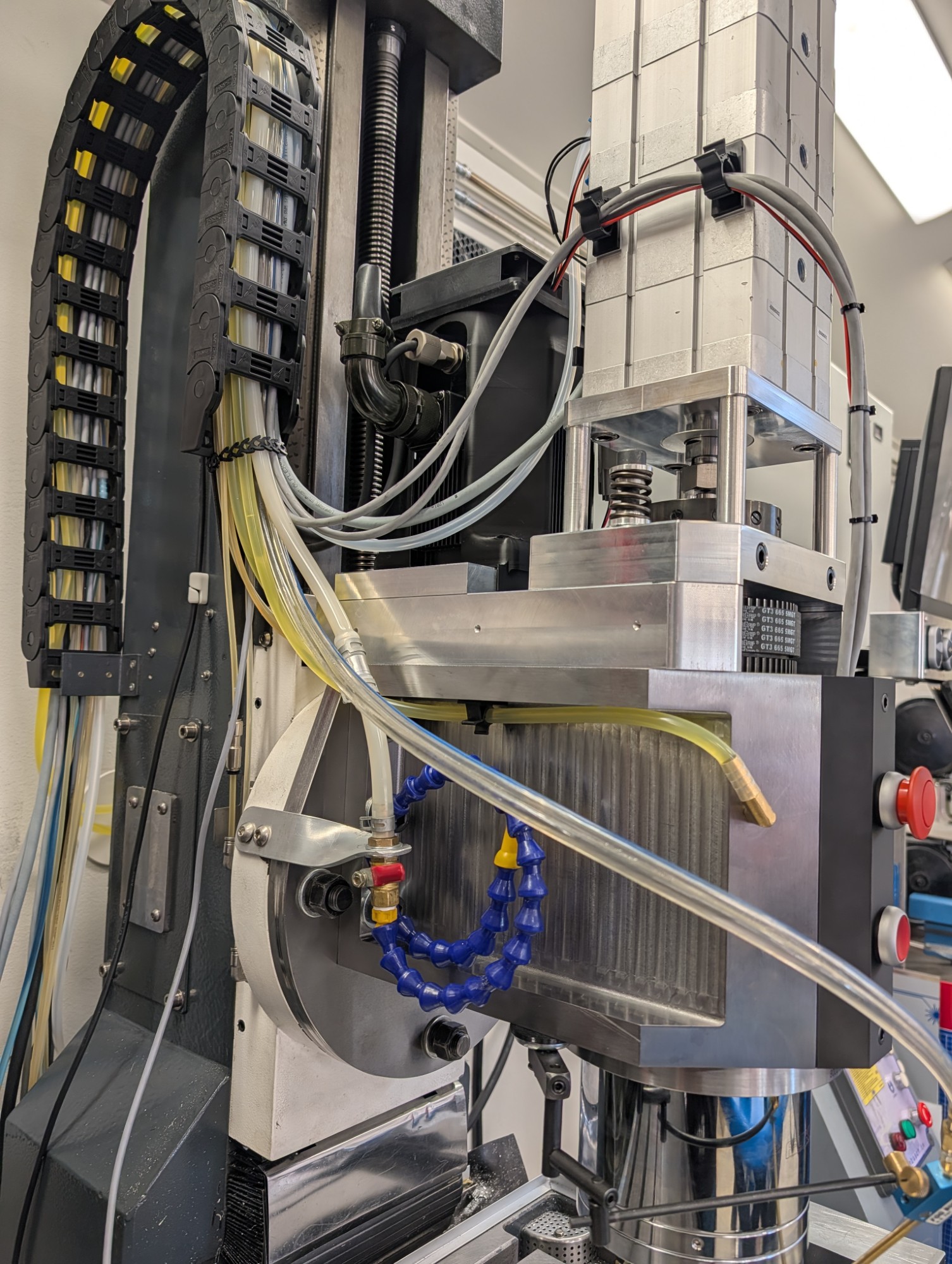
With that done I tackled the cable chain along with all the wires and hoses.
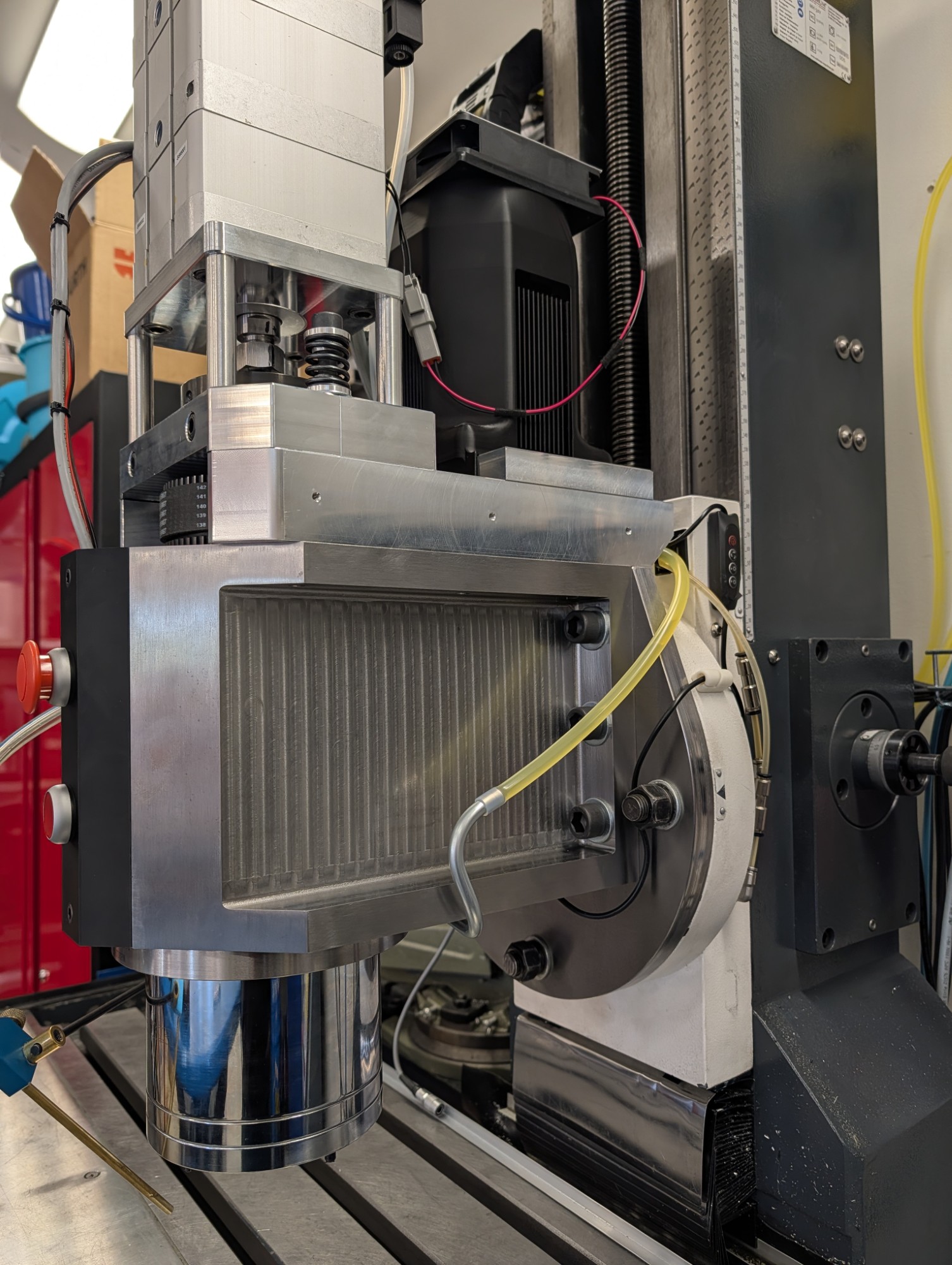
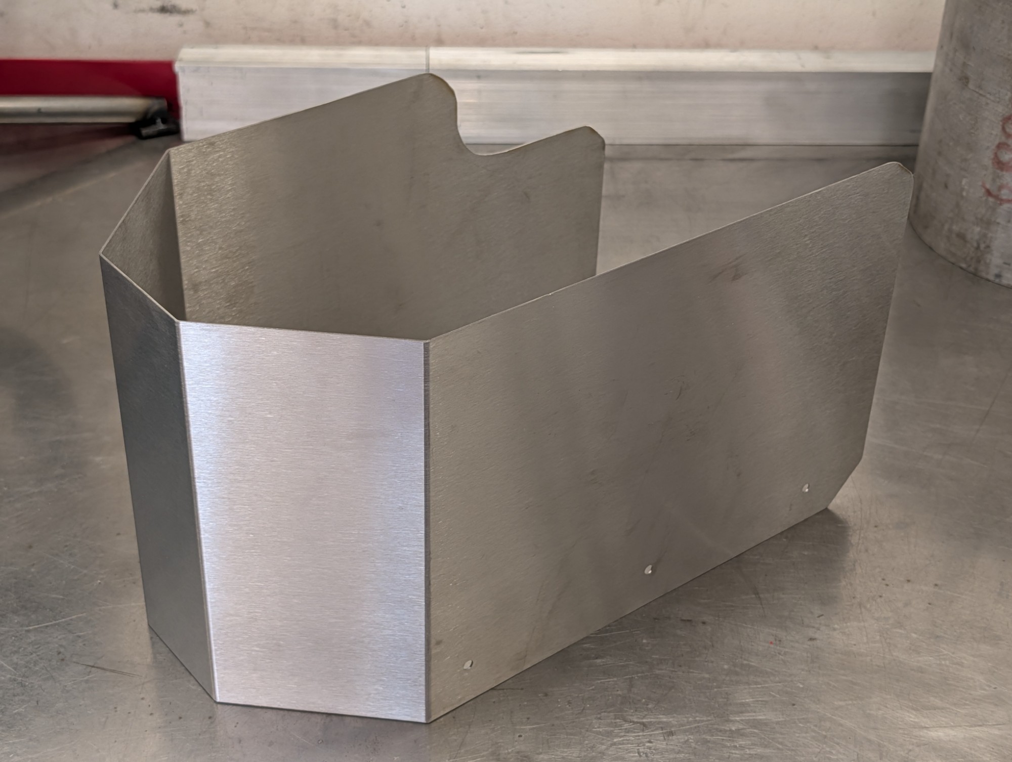
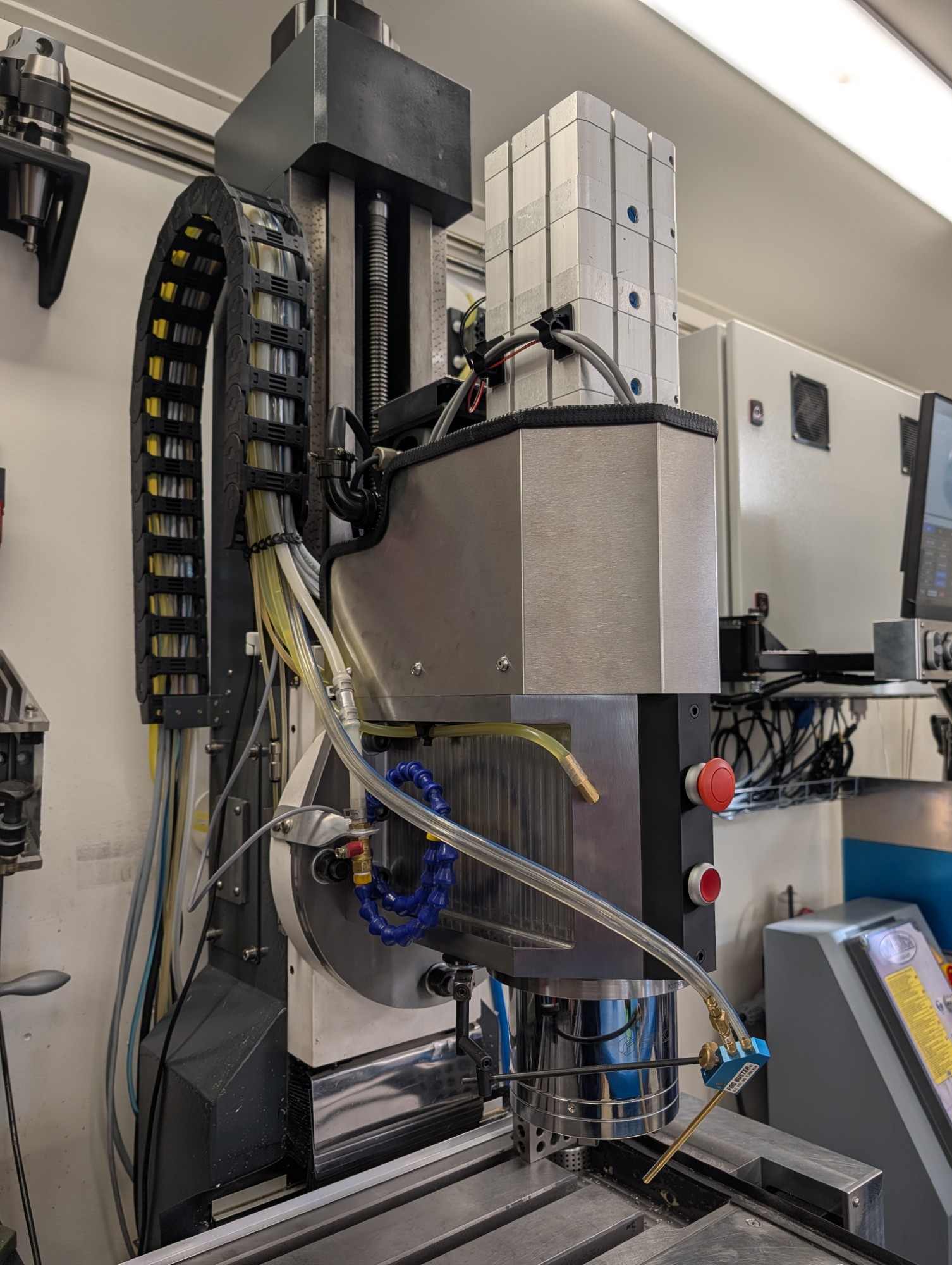
With that in order I turned my attention to the stainless cover I had laser cut and CNC bent a while back. I had to manually make a cut out for the connector of the spindle servo which I had forgotten to take into account. But I think it came out okay anyway.
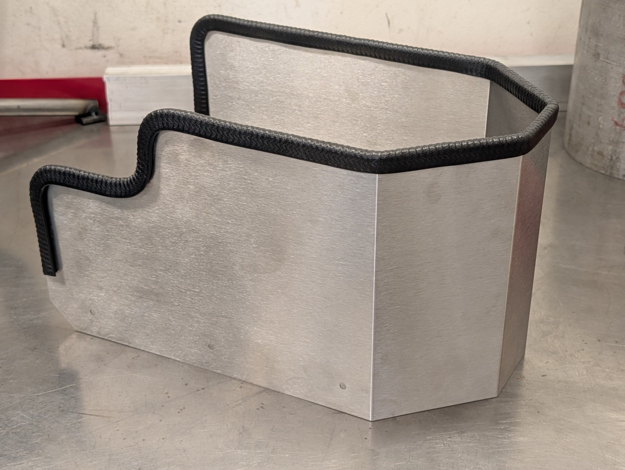
Fitted it with a rubber strip to cover the sharp edges.
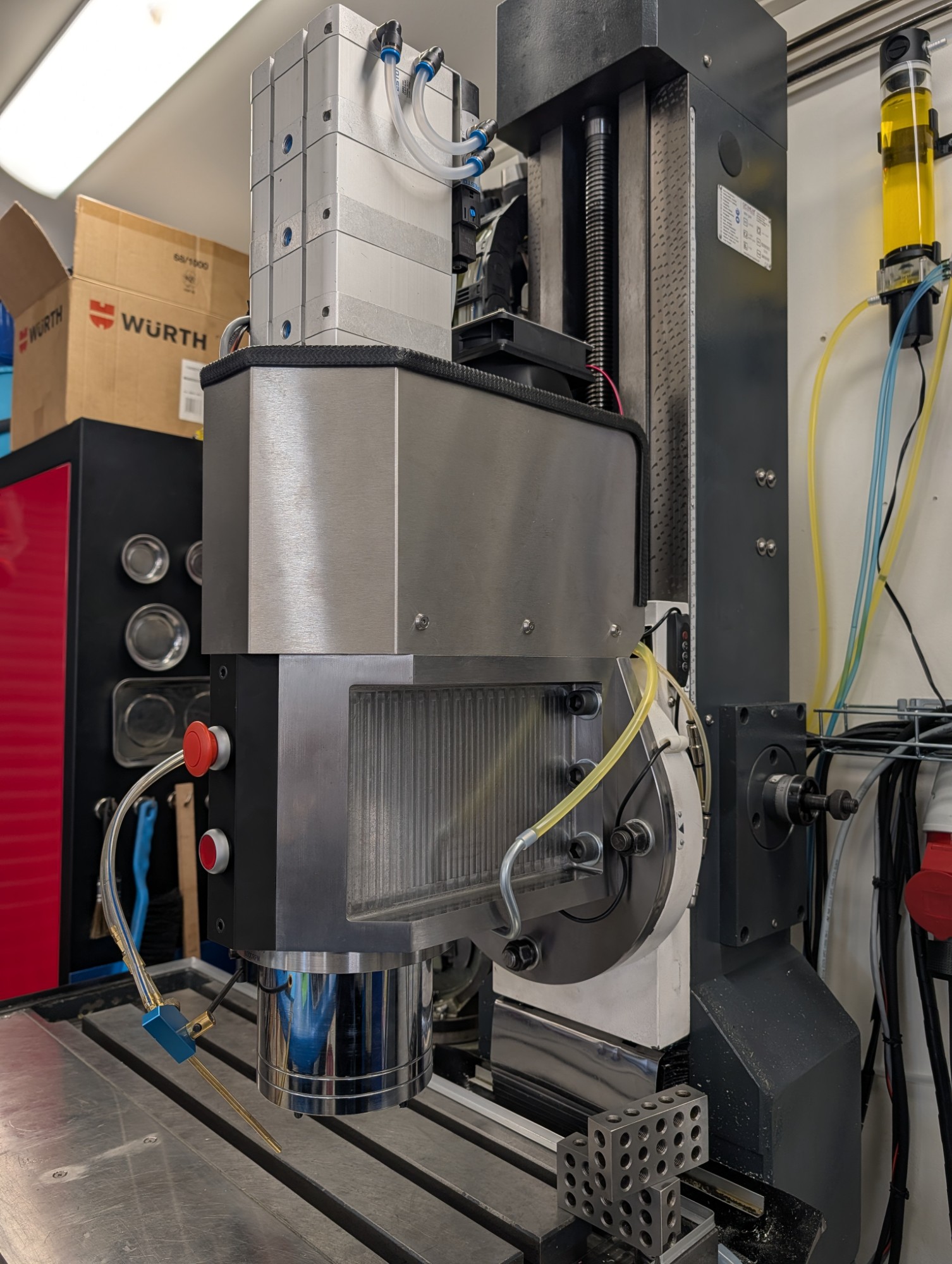
Here is how the machine looks with the cover installed.
The power supply is constantly powered but I switch the output side using a solid state relay so that the cooling only runs when the spindle is on.
However the pump proved to be a bit noisy and way too powerful give the small diameter hose I'm running. So added a 7.5Ω resistor in series with the pump to bring the voltage down to 8V which made it much quieter and brought the flow down to a more suitable level.
With that done I tackled the cable chain along with all the wires and hoses.
With that in order I turned my attention to the stainless cover I had laser cut and CNC bent a while back. I had to manually make a cut out for the connector of the spindle servo which I had forgotten to take into account. But I think it came out okay anyway.
Fitted it with a rubber strip to cover the sharp edges.
Here is how the machine looks with the cover installed.
Attachments:
Please Log in or Create an account to join the conversation.
- Unlogic
- Offline
- Elite Member
-
Less
More
- Posts: 257
- Thank you received: 128
25 Sep 2026 05:44 #349856
by Unlogic
Replied by Unlogic on topic Optimum Optimill MH50V CNC conversion
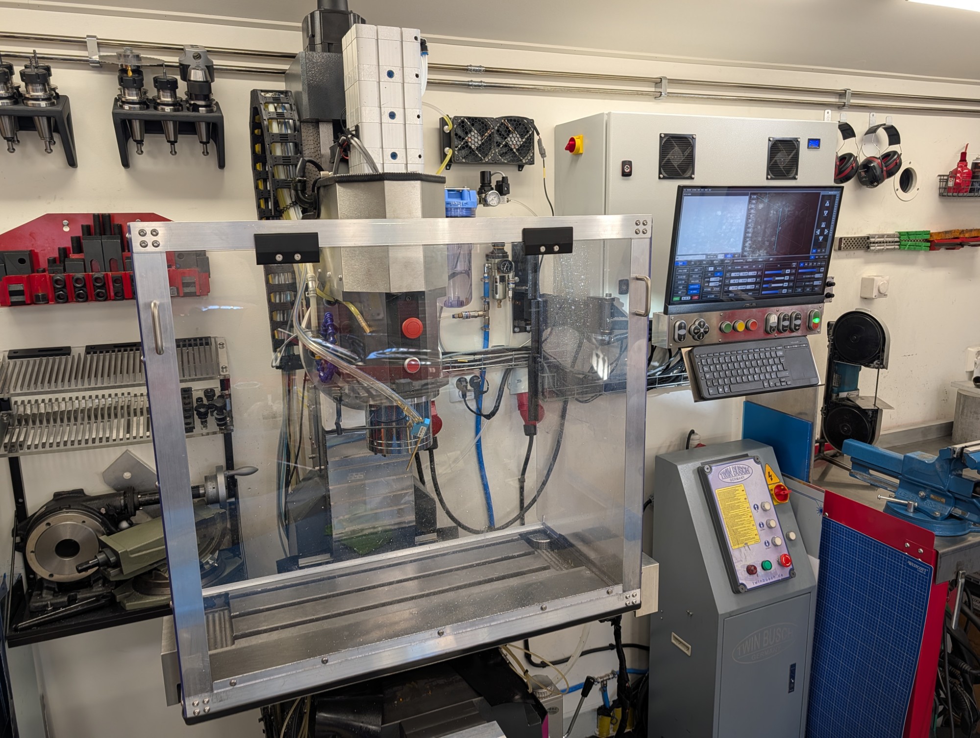
And here is how it looks with the enclosure mounted on the table.
With all the mechanical bits in place I wrote a short spindle run-in program that increased the spindle rpm in increments of 500 up to 6000 and ran for 10 minutes at each increment.
Everything worked well until I reached 5000 rpm when the spindle servo threw a fault. Turned out I had the max allowed rpm set to 4500 in the servo drive since my old spindle couldn't go that high.
Fixed that and immediately ran into the next issue, the default rpm limit for the encoder speed in the servo drive also had to be increased. In the end I had to bump up quite a few parameters including tweaking the inertia to get the full 6000 rpm range enabled in the drive.
The next issue I ran into was that the rpm would not go above 5610 when commanded from LinuxCNC. Turned out that I had to adjust the settings in LinuxCNC regarding how many steps (pulses) per seconds that could be sent to the spindle. Just as with the drive I had set these value quite low for my old spindle when I did the configuration years ago.
With all that sorted I could finally finish the run-in program. But when the program stopped after running the final increment at 6000 rpm I ran into the next issue. The drive threw a fault regarding an overheated regenerative braking resistor.
Going from 3500 to 6000 rpm along with the increased the inertia from the larger spindle overwhelmed the built in regenerative braking resistor in the spindle drive when coming to a full stop from 6000 rpm. I managed to get it somewhat working for now by increasing the time for the spindle ramp down by a few seconds.
But if I stop the spindle a few times in successions from full rpm I still get the fault. So I ended up ordering an external 800W braking resistor which should be here early next week.
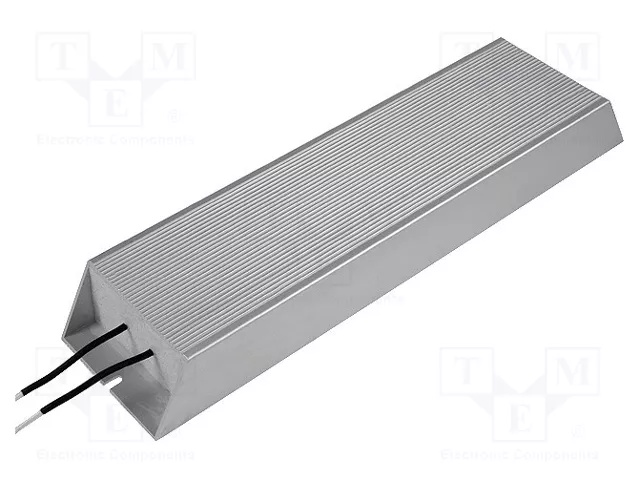
If I managed to follow the formulas in the Delta B3 manual correctly a 550W resistor should be enough for my setup. So hopefully 800W will give me plenty of headroom.
However after all the troubleshooting I was still very satisfied at the end of the day when I removed the BT40 tool holder which had been in the spindle all day running at various rpm's. It was essentially the same temperature as when I had picked it up from the tool shelf in the morning.
The new spindle is running significantly cooler compared to the old one. This can also be seen on the idle load.
With the old spindle I would have an idle load of 17-20% on the 2kw spindle servo just running idle at 3500 rpm. The new spindle sits between 1-6% depending on rpm, at 6000 the load is just 1-2% which is very promising.
With all the mechanical bits in place I wrote a short spindle run-in program that increased the spindle rpm in increments of 500 up to 6000 and ran for 10 minutes at each increment.
Everything worked well until I reached 5000 rpm when the spindle servo threw a fault. Turned out I had the max allowed rpm set to 4500 in the servo drive since my old spindle couldn't go that high.
Fixed that and immediately ran into the next issue, the default rpm limit for the encoder speed in the servo drive also had to be increased. In the end I had to bump up quite a few parameters including tweaking the inertia to get the full 6000 rpm range enabled in the drive.
The next issue I ran into was that the rpm would not go above 5610 when commanded from LinuxCNC. Turned out that I had to adjust the settings in LinuxCNC regarding how many steps (pulses) per seconds that could be sent to the spindle. Just as with the drive I had set these value quite low for my old spindle when I did the configuration years ago.
With all that sorted I could finally finish the run-in program. But when the program stopped after running the final increment at 6000 rpm I ran into the next issue. The drive threw a fault regarding an overheated regenerative braking resistor.
Going from 3500 to 6000 rpm along with the increased the inertia from the larger spindle overwhelmed the built in regenerative braking resistor in the spindle drive when coming to a full stop from 6000 rpm. I managed to get it somewhat working for now by increasing the time for the spindle ramp down by a few seconds.
But if I stop the spindle a few times in successions from full rpm I still get the fault. So I ended up ordering an external 800W braking resistor which should be here early next week.
If I managed to follow the formulas in the Delta B3 manual correctly a 550W resistor should be enough for my setup. So hopefully 800W will give me plenty of headroom.
However after all the troubleshooting I was still very satisfied at the end of the day when I removed the BT40 tool holder which had been in the spindle all day running at various rpm's. It was essentially the same temperature as when I had picked it up from the tool shelf in the morning.
The new spindle is running significantly cooler compared to the old one. This can also be seen on the idle load.
With the old spindle I would have an idle load of 17-20% on the 2kw spindle servo just running idle at 3500 rpm. The new spindle sits between 1-6% depending on rpm, at 6000 the load is just 1-2% which is very promising.
Attachments:
The following user(s) said Thank You: tommylight
Please Log in or Create an account to join the conversation.
- Unlogic
- Offline
- Elite Member
-
Less
More
- Posts: 257
- Thank you received: 128
30 Sep 2026 07:08 #350000
by Unlogic
Replied by Unlogic on topic Optimum Optimill MH50V CNC conversion
I received the braking resistor yesterday and mounted it on the left side of the cabinet. The cables that came with it were just long enough to reach all the way to the spindle drive.
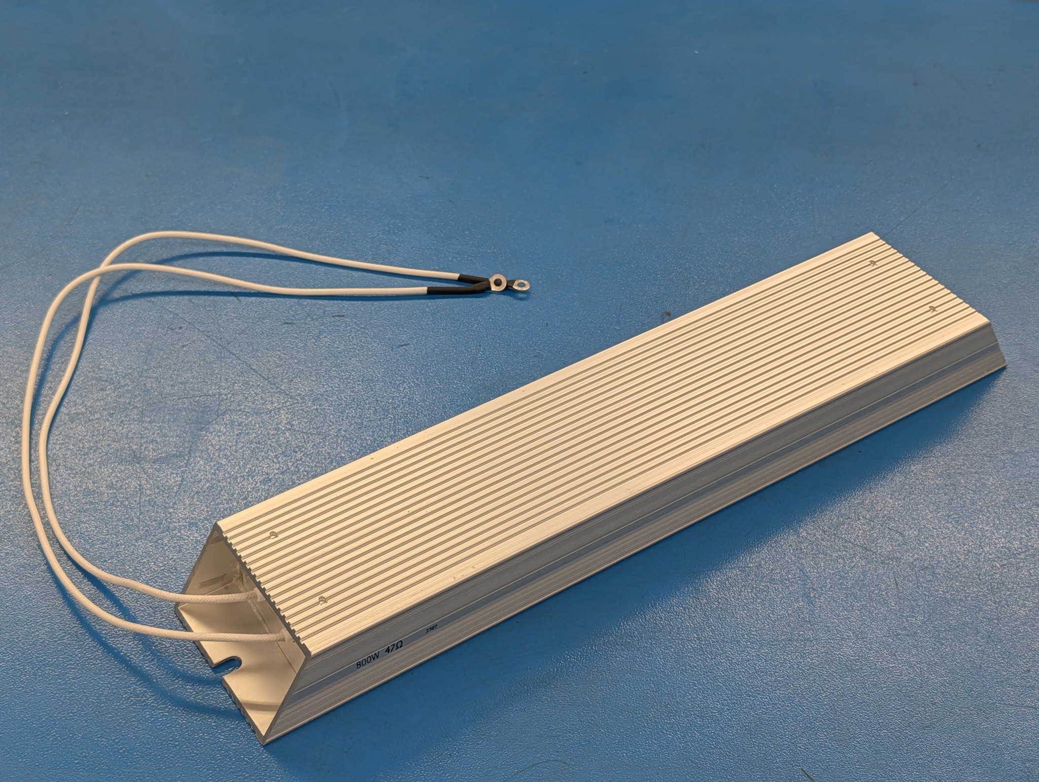
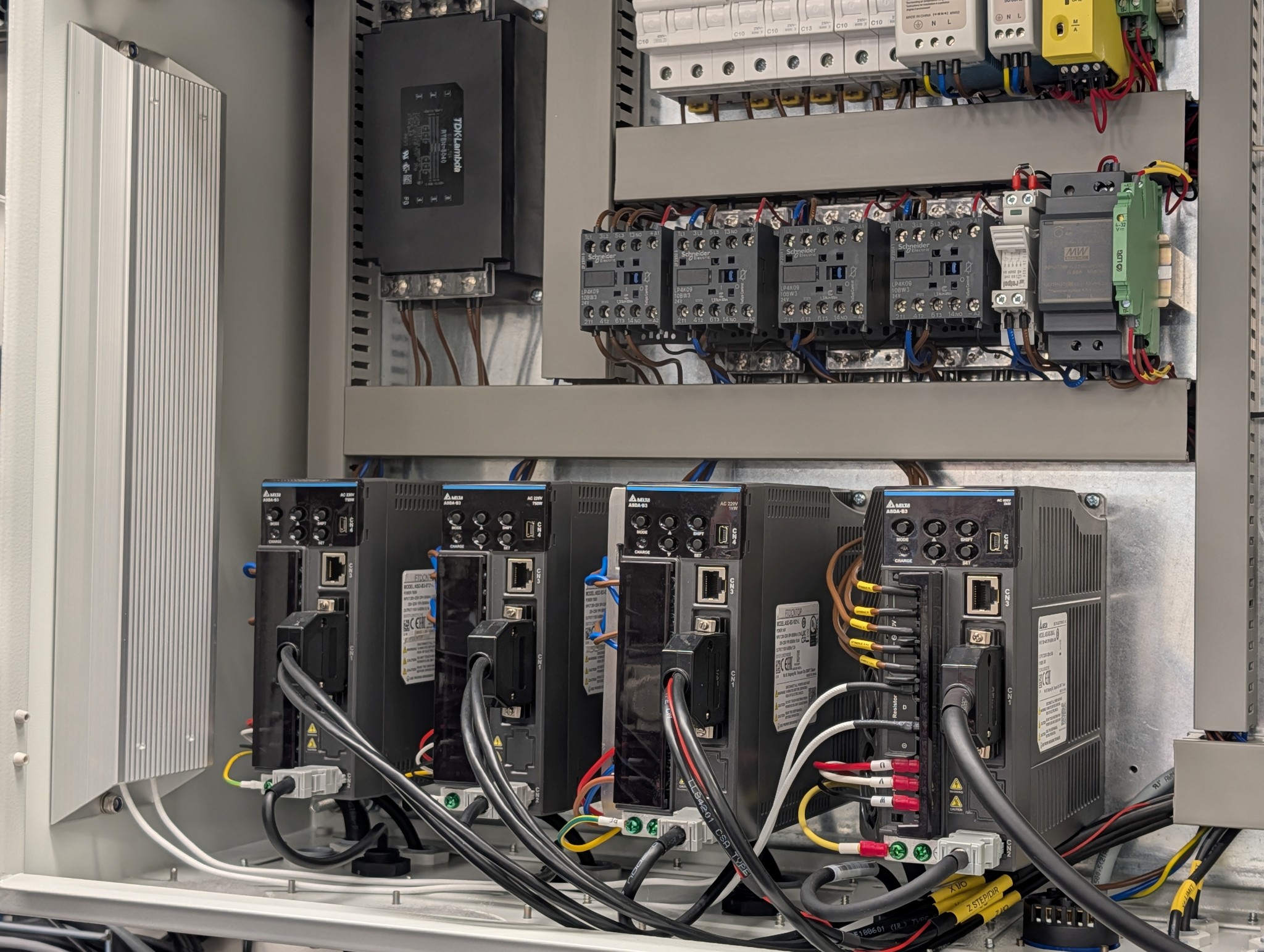
With the braking resistor installed and the parameters set in the spindle drive the faults when stopping the spindle from high RPM disappeared.
As the machine seemed to be ready for the first test cuts I cleaned the vices in the parts cleaner and installed them.
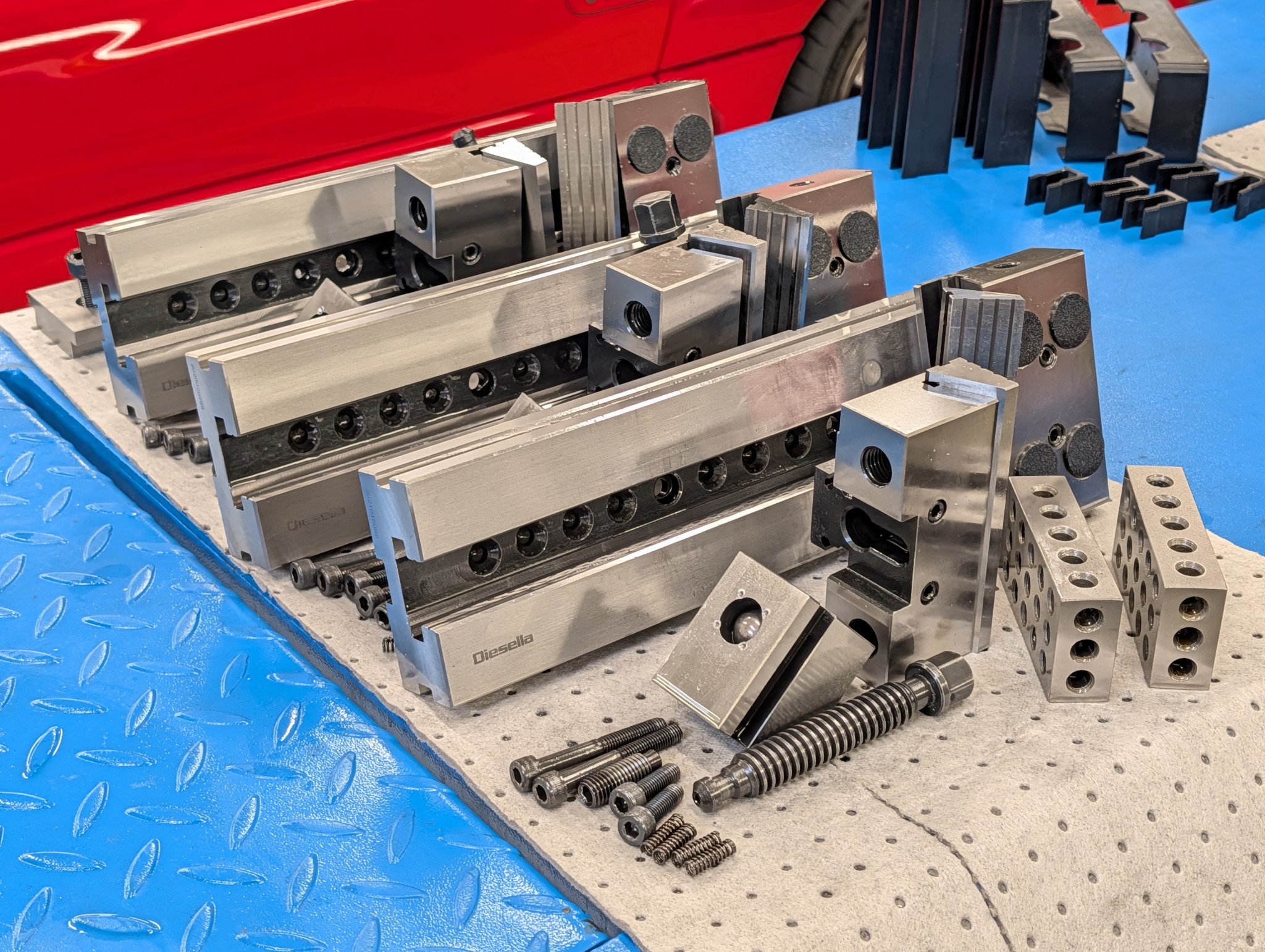
Getting all three of them trammed in took it's time as usual...
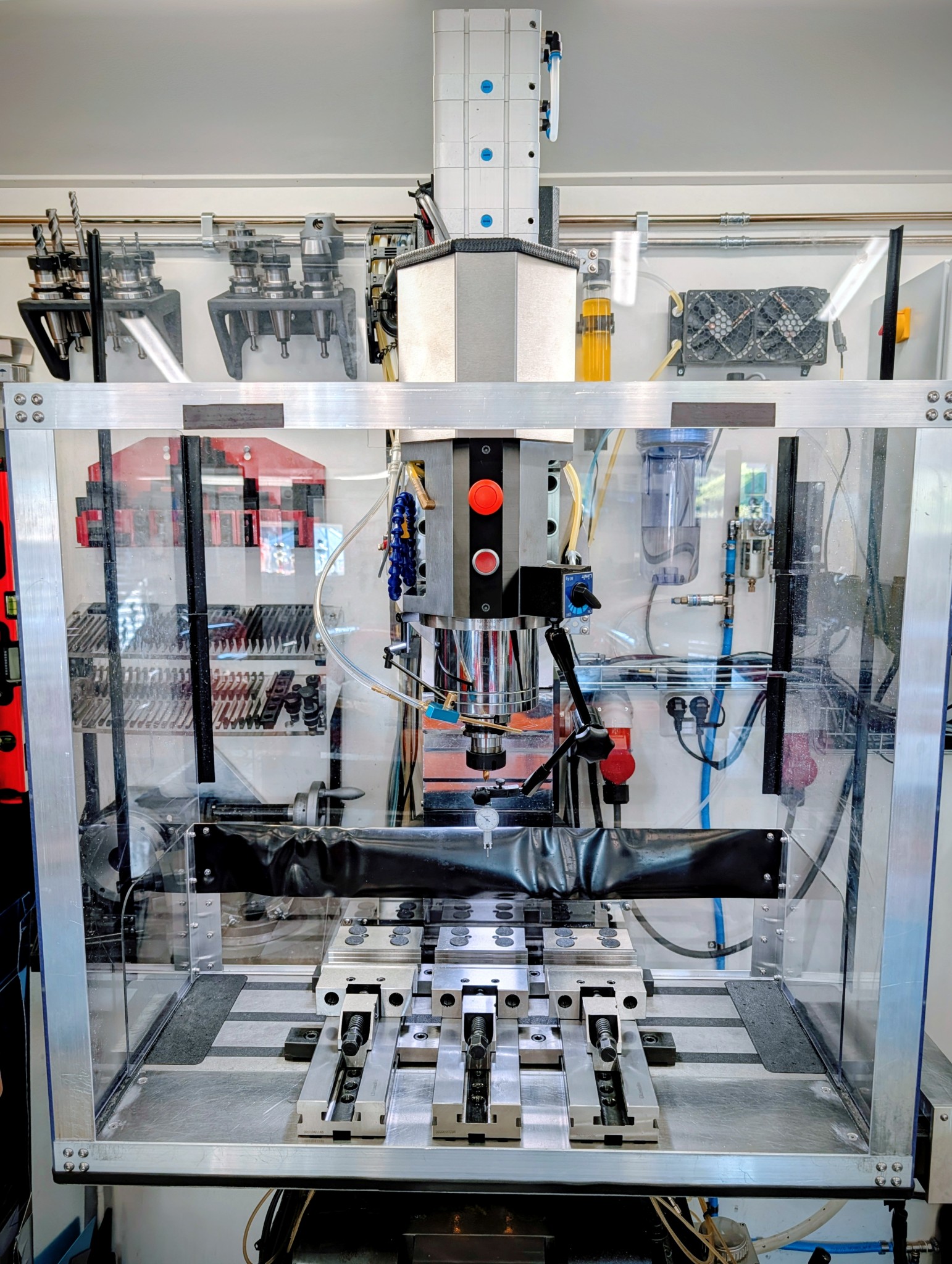
For the first nervous test cuts with the new spindle I used a piece of 7075 aluminum.
I started with an 80 mm face mill and immediately noticed a clear improvement in surface finish which I hadn't expected.
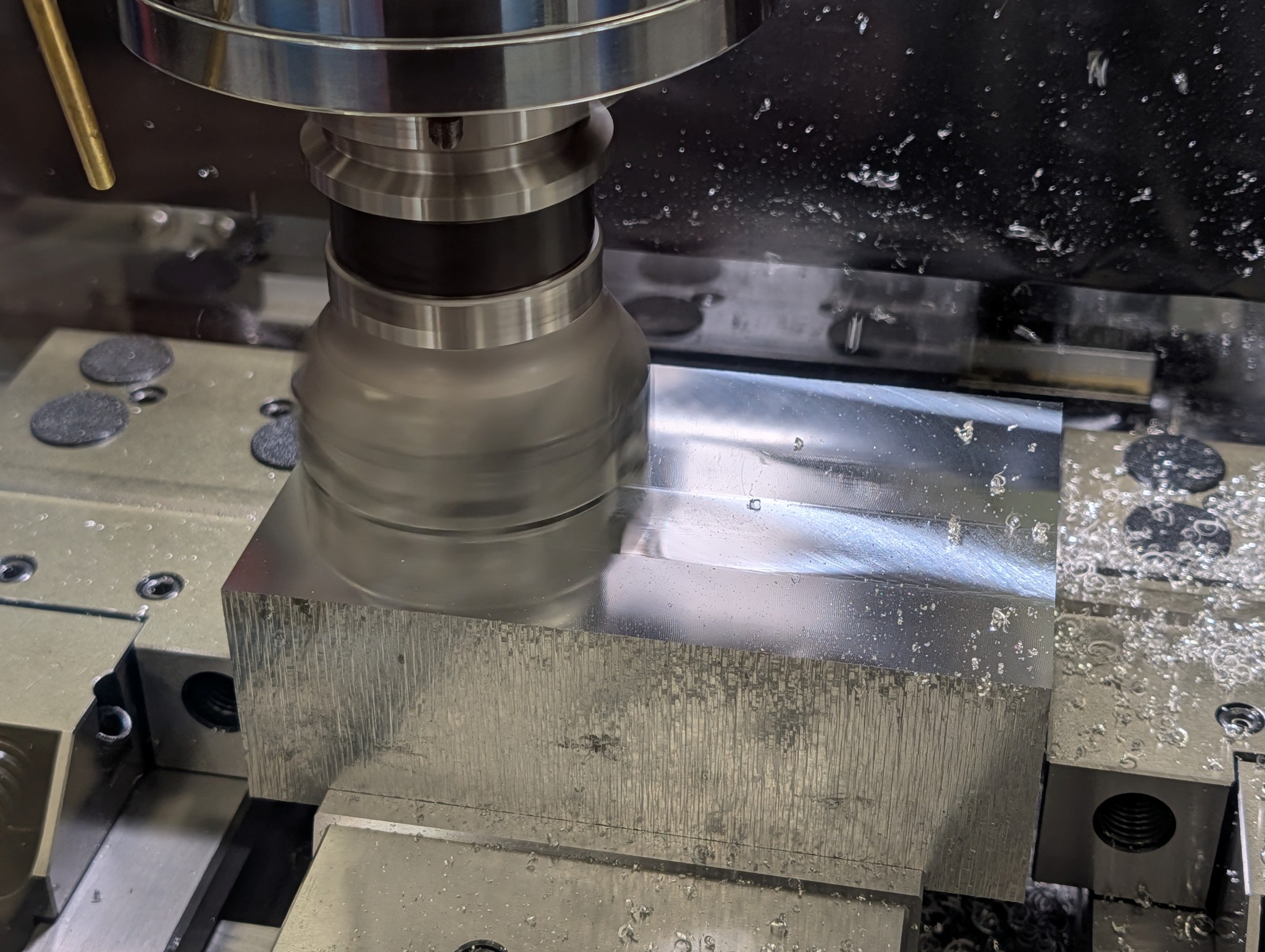
Next I milled the sides with a 16mm DLC coated solid end mill. The resulting finish was something I've never seen on this machine before.
This was just a quick cut with a width of 0,5 mm so this feels very promising. I'll report back when I've milled a few real parts.
With the braking resistor installed and the parameters set in the spindle drive the faults when stopping the spindle from high RPM disappeared.
As the machine seemed to be ready for the first test cuts I cleaned the vices in the parts cleaner and installed them.
Getting all three of them trammed in took it's time as usual...
For the first nervous test cuts with the new spindle I used a piece of 7075 aluminum.
I started with an 80 mm face mill and immediately noticed a clear improvement in surface finish which I hadn't expected.
Next I milled the sides with a 16mm DLC coated solid end mill. The resulting finish was something I've never seen on this machine before.
This was just a quick cut with a width of 0,5 mm so this feels very promising. I'll report back when I've milled a few real parts.
Attachments:
The following user(s) said Thank You: tommylight
Please Log in or Create an account to join the conversation.
Moderators: piasdom
Time to create page: 2.012 seconds