Considering a Full Rewire on a Working Schaublin 125 CNC
- spumco
- Offline
- Platinum Member
-

Less
More
- Posts: 2119
- Thank you received: 879
06 May 2026 03:16 #346193
by spumco
Replied by spumco on topic Considering a Full Rewire on a Working Schaublin 125 CNC
Next thought about the collet closer...
I'd measure the spindle shaft and see if it's still round. If it is, and you can get the bearing rings out, it could be possible to use the air fitting threaded holes to inject Moglice in to the annulus between the rotary union bore and the part it rides on.
Once its cured and you've removed it - not a trivial task to be sure - you could use a grooving tool to clear out the existing air grooves. Maybe even hone the cured Moglice to provide a much smaller gap - less air leakage, but still some to counter dust ingress and provide a little cooling.
If you're not keen on Moglice, maybe shrink-fit or glue a couple pieces of thin-wall brass or bronze tube inside the union - leave a gap between them for the air grooves - and bore it out to a closer fit.
Last option would be to groove the union ID to fit a couple of teflon seals. Shouldn't be too hard to find some low-tension rings that just fit around the rotating part and don't drag too much.
The following user(s) said Thank You: Dudelbert
Please Log in or Create an account to join the conversation.
- Dudelbert
- Offline
- Senior Member
-

Less
More
- Posts: 79
- Thank you received: 20
06 May 2026 04:05 #346194
by Dudelbert
Replied by Dudelbert on topic Considering a Full Rewire on a Working Schaublin 125 CNC
Thanks for the ideas. I will try running the spindle in open loop and see what that does. I noticed the spindle variations in the video as well, while using the machine, I did not even notice them. More spindle tuning is needed, it seems.
The filter is set to “True” right now. I will try turning it off to make sure that does not change anything.
Regarding the collet closer, I thought about cutting grooves, but as the part is hardened, I don’t like my chances of getting that right. Moglice seems like the best way. I remember Robin Renzetti using it on his D-bit grinder.
The only issue there is that the shaft has holes to port the air to the cylinder. I would have to close these in some reversible way and then machine them back down to the shaft diameter to be able to remove the collar after injecting the goo. Epoxy putty, maybe?
Please Log in or Create an account to join the conversation.
- spumco
- Offline
- Platinum Member
-
Less
More
- Posts: 2119
- Thank you received: 879
06 May 2026 17:33 #346209
by spumco
Replied by spumco on topic Considering a Full Rewire on a Working Schaublin 125 CNC
You don't have to cast the Moglice in place on the closer. You could turn a piece of stock to the same (or slightly larger) OD, polish it, and use that as the male 'plug'.
Could even make it solid stock with a threaded hole to use for pulling/pressing the Mogliced sleeve off.
And yes, Robin Renzetti's D-bit grinder was my inspiration, too.
Could even make it solid stock with a threaded hole to use for pulling/pressing the Mogliced sleeve off.
And yes, Robin Renzetti's D-bit grinder was my inspiration, too.
Please Log in or Create an account to join the conversation.
- Dudelbert
- Offline
- Senior Member
-
Less
More
- Posts: 79
- Thank you received: 20
06 May 2026 17:40 #346210
by Dudelbert
Replied by Dudelbert on topic Considering a Full Rewire on a Working Schaublin 125 CNC
I thought about this a lot since yesterday and arrived at pretty much the same solution. It is nice to have that idea confirmed by you, thanks for that.
oh and, the stuff seems to be relatively expensive.
If anyone has a project and needs a small amount (and is located in Central Europe), please give me a shout. Then I can send the rest after I am done, so it does not go to waste.
oh and, the stuff seems to be relatively expensive.
If anyone has a project and needs a small amount (and is located in Central Europe), please give me a shout. Then I can send the rest after I am done, so it does not go to waste.
Please Log in or Create an account to join the conversation.
- spumco
- Offline
- Platinum Member
-
Less
More
- Posts: 2119
- Thank you received: 879
06 May 2026 17:49 #346212
by spumco
The true test of someone's intelligence is how much they agree with you

I bet Mark's (RotarySMP) collet closer leaks air too. Maybe not as bad as yours, but likely needs a 'tune-up' after all these years.
Replied by spumco on topic Considering a Full Rewire on a Working Schaublin 125 CNC
I thought about this a lot since yesterday and arrived at pretty much the same solution. It is nice to have that idea confirmed by you, thanks for that.
The true test of someone's intelligence is how much they agree with you
I bet Mark's (RotarySMP) collet closer leaks air too. Maybe not as bad as yours, but likely needs a 'tune-up' after all these years.
Please Log in or Create an account to join the conversation.
- Dudelbert
- Offline
- Senior Member
-
Less
More
- Posts: 79
- Thank you received: 20
06 May 2026 17:56 #346213
by Dudelbert
Replied by Dudelbert on topic Considering a Full Rewire on a Working Schaublin 125 CNC
According to Mark, it is not. And let’s see how complicated it will get, but I would not attempt this if I thought I could avoid it.

I am not sure if that is agreement or a dig at me.
The true test of someone's intelligence is how much they agree with you
Please Log in or Create an account to join the conversation.
- spumco
- Offline
- Platinum Member
-
Less
More
- Posts: 2119
- Thank you received: 879
06 May 2026 18:19 #346214
by spumco
Replied by spumco on topic Considering a Full Rewire on a Working Schaublin 125 CNC
Not a dig at all - just a tongue-in-cheek saying I found years ago.
Works better in person, since non-verbal clues (wink, wink) help both people understand how absurdly fatuous it is.
Works better in person, since non-verbal clues (wink, wink) help both people understand how absurdly fatuous it is.
The following user(s) said Thank You: tommylight
Please Log in or Create an account to join the conversation.
- Dudelbert
- Offline
- Senior Member
-
Less
More
- Posts: 79
- Thank you received: 20
07 May 2026 15:30 - 07 May 2026 15:31 #346252
by Dudelbert
Replied by Dudelbert on topic Considering a Full Rewire on a Working Schaublin 125 CNC
I finally found the problem with the threading. Should have found it much earlier.It’s the belt.
It gets chewed up. Opening the side panel, I found belt-colored dust, but the belt still locked fine, at least from the side. Looking closer showed that the teeth are broken up from the middle outward (see picture).
I found one tooth gap with some hard thing in it, so I assume that my initial cleaning when installing the belt was not very thorough and I overlooked that.
After cleaning that out and reinstalling the already damaged belt, I could thread fine. But I think this will not last long, so I ordered new belts and will install them after VERY thoroughly cleaning both pulleys.
It’s really typical for me that the solution to a month of problems is: “You should have cleaned the thing better.”
Last edit: 07 May 2026 15:31 by Dudelbert.
The following user(s) said Thank You: RotarySMP, spumco
Please Log in or Create an account to join the conversation.
- spumco
- Offline
- Platinum Member
-
Less
More
- Posts: 2119
- Thank you received: 879
07 May 2026 16:13 - 07 May 2026 16:15 #346254
by spumco
Replied by spumco on topic Considering a Full Rewire on a Working Schaublin 125 CNC
Is that supposed to be a T5 belt profile? I've never seen a timing pulley with a 'tit' on the tooth crest.
Is the tit on the pulley teeth from wear, or is it some substance that got in the belt tooth valley groove and stuck to the teeth? And that's what you're cleaning?
To clarify, here's a T5 belt profile from Misumi. I think the groove is there to help air escape at higher speeds (noise reduction).
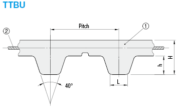
Is the tit on the pulley teeth from wear, or is it some substance that got in the belt tooth valley groove and stuck to the teeth? And that's what you're cleaning?
To clarify, here's a T5 belt profile from Misumi. I think the groove is there to help air escape at higher speeds (noise reduction).
Attachments:
Last edit: 07 May 2026 16:15 by spumco. Reason: Add pic
Please Log in or Create an account to join the conversation.
- Dudelbert
- Offline
- Senior Member
-
Less
More
- Posts: 79
- Thank you received: 20
07 May 2026 16:30 #346255
by Dudelbert
Replied by Dudelbert on topic Considering a Full Rewire on a Working Schaublin 125 CNC
The dark line in the middle of the tooth is just the last bit that still has the original surface, with a bit of dirt that makes it darker. On both sides, it is mostly obliterated. I assume that is what you mean by “tit.”
And I think the gap between the teeth is also to reduce the smallest possible bending angle, in addition to the reasons you listed.
And I think the gap between the teeth is also to reduce the smallest possible bending angle, in addition to the reasons you listed.
Please Log in or Create an account to join the conversation.
Moderators: piasdom
Time to create page: 0.332 seconds