Considering a Full Rewire on a Working Schaublin 125 CNC
- andypugh
-

- Offline
- Moderator
-

Less
More
- Posts: 19875
- Thank you received: 4642
18 Apr 2026 23:22 #345712
by andypugh
Replied by andypugh on topic Considering a Full Rewire on a Working Schaublin 125 CNC
1) To operate the contactors from a PID you could use a WCOMP HAL component. Use the "over" and "under" pins to drive the contactors and set up the max and min some small distance above and below zero to prevent hunting.
linuxcnc.org/docs/stable/html/man/man9/wcomp.9.html
2) Before looking at the G76 G-code, make sure that spindle.0.revs increases by exactly 1.0 for every rotation of the spindle.
linuxcnc.org/docs/stable/html/man/man9/wcomp.9.html
2) Before looking at the G76 G-code, make sure that spindle.0.revs increases by exactly 1.0 for every rotation of the spindle.
Please Log in or Create an account to join the conversation.
- RotarySMP
-

- Offline
- Platinum Member
-

Less
More
- Posts: 1628
- Thank you received: 595
19 Apr 2026 06:41 #345717
by RotarySMP
Replied by RotarySMP on topic Considering a Full Rewire on a Working Schaublin 125 CNC
The main errors:
K0.75 is radius mode while in diameter mode.
I1 is radius mode (X34-X32) while in diameter mode
G96 D2500 ? 2500 m/min surface speed? Cutting steel with carbide is typically only 1/10 that or less.
Maybe consider G97 S500 just to remove a variable while you are getting used it it?
Assuming a thread major diameter (stock OD) of 32, with you drive line at X34, I-2. In practice, the major diameter is probably more like P/8 smaller. Somewhere around 31.8mm. Andy has programmed all that into his lathe macros, so you just give it major diameter (32mm) and it takes a first turning path at P/8 smaller before starting threading.
Since this is G7 diameter mode, the final depth K is also in diameter, so that will be 32-30.5 K1.5. Actually it is more likely to be about 30.38, so you will tweak this number to get your thread to fit, if you don't have perfect full profile inserts. Dont be surprised that you need around K1.62 to get the nut to fit.
J0.3 is reasonable. You will need lots of passes. See if you can get the insert to survive at J0.5
The R 1.6 means your cut will get heavier at each pass. I tend to set that at R2 for constant area, of course leading o increased number of passes.
The rest looks good.
G7 G18 G21 G90 G94
G0 X34 Z10
G97 S500 M3 M8
G76 Z-15 P1.5 I-2 K1.5 J0.5 Q29 H2 E0.75 L2
Please Log in or Create an account to join the conversation.
- spumco
- Offline
- Platinum Member
-
Less
More
- Posts: 2126
- Thank you received: 882
19 Apr 2026 14:05 #345735
by spumco
"D" is max spindle speed, not desired surface speed.
Replied by spumco on topic Considering a Full Rewire on a Working Schaublin 125 CNC
G96 D2500 ? 2500 m/min surface speed? Cutting steel with carbide is typically only 1/10 that or less.
Maybe consider G97 S500 just to remove a variable while you are getting used it it?
"D" is max spindle speed, not desired surface speed.
The following user(s) said Thank You: RotarySMP
Please Log in or Create an account to join the conversation.
- Dudelbert
- Offline
- Senior Member
-

Less
More
- Posts: 79
- Thank you received: 20
19 Apr 2026 17:59 #345744
by Dudelbert
Replied by Dudelbert on topic Considering a Full Rewire on a Working Schaublin 125 CNC
Thanks for the replies. The spindle.0.revs seems to be right when turning by hand, and when driving with the VFD active it is hard to tell exactly, but it seems to be correct as well.
Trying in constant speed instead of surface speed is a good idea, I will try that next.
And regarding diameter and radius, the man page I even linked says:
Note: When G7 Lathe Diameter Mode is in force, the values for I, J, and K are diameter measurements. When G8 Lathe Radius Mode is in force, the values for I, J, and K are radius measurements.
I don’t know how I overlooked that, it is really obvious now.
Please Log in or Create an account to join the conversation.
- Dudelbert
- Offline
- Senior Member
-
Less
More
- Posts: 79
- Thank you received: 20
22 Apr 2026 09:50 - 22 Apr 2026 09:58 #345833
by Dudelbert
Replied by Dudelbert on topic Considering a Full Rewire on a Working Schaublin 125 CNC
I am still struggling with threading.I have tested it at very low speed (100 RPM) in the hope to see something that helps me find what is wrong. But I cannot really say what I am looking at. The result is repeatable, and at least to me it looks like a constant offset that makes it wrong. I have set the cross-slide angle to 0, so that is not the reason. It is supposed to be an M8.
I would have expected a more random result if the spindle index was jittery, so that is probably not it. And spindle.0.revs, I tested it by turning the spindle by hand 25 turns, and spindle.0.revs was almost exactly 25. The remaining very small error can easily be attributed to me doing it by hand.
Additionally, I set the spindle to 1200 RPM and let it run. After it settled, I made a video filming the HAL Show screen and watching spindle.0.revs so I could later check it, and I got 1206 RPM that way.
I tried to make sure that the spindle really had 1200 RPM with a laser tachometer and by watching the encoder velocity RPM. Both agree within a margin of under 10 RPM. I don’t have any RPM measurement tools that are more reliable or accurate.
All these tests point me in the direction of the spindle encoder being OK. Are these tests the wrong way of testing this? What else can it be?
Last edit: 22 Apr 2026 09:58 by Dudelbert.
Please Log in or Create an account to join the conversation.
- rodw
-

- Away
- Platinum Member
-
Less
More
- Posts: 11994
- Thank you received: 4084
22 Apr 2026 10:03 #345835
by rodw
Replied by rodw on topic Considering a Full Rewire on a Working Schaublin 125 CNC
These are cheap as (can find them for half this price) and are well worth having
www.amazon.com.au/Mengshen-Tachometer-2-...ctive/dp/B0BFHXMKR3/
www.amazon.com.au/Mengshen-Tachometer-2-...ctive/dp/B0BFHXMKR3/
The following user(s) said Thank You: Dudelbert
Please Log in or Create an account to join the conversation.
- Dudelbert
- Offline
- Senior Member
-
Less
More
- Posts: 79
- Thank you received: 20
22 Apr 2026 10:06 #345836
by Dudelbert
Replied by Dudelbert on topic Considering a Full Rewire on a Working Schaublin 125 CNC
That is the exact type of “laser tachometer” I used. I agree that they are useful.
Please Log in or Create an account to join the conversation.
- RotarySMP
-
- Offline
- Platinum Member
-
Less
More
- Posts: 1628
- Thank you received: 595
22 Apr 2026 14:56 #345841
by RotarySMP
Replied by RotarySMP on topic Considering a Full Rewire on a Working Schaublin 125 CNC
I double checked our ini's, and we both have the encoder scaling set to 8000 pulses/rev. Not sure what would cause that drift you are seeing.
The following user(s) said Thank You: Dudelbert
Please Log in or Create an account to join the conversation.
- spumco
- Offline
- Platinum Member
-
Less
More
- Posts: 2126
- Thank you received: 882
22 Apr 2026 20:31 - 22 Apr 2026 20:35 #345855
by spumco
Spindle speed: there is a bug in LCNC which causes a different start point during spindle synchronized motion if successive passes aren't at the same speed. Constant surface speed is not OK in multi-pass threading. Same reason folks have reported trying to do thread repair and lining up on a thread by hand, only to wipe out the threads when the spindle is run because the start point is different.
I don't think this was your problem, as I did a screen-cap of your video looking for the start point on each pass. Pretty constant start point near as I can tell.
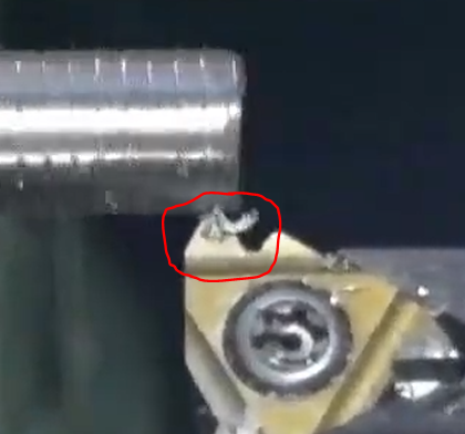
It looks like your thread is cutting mostly on theleft (leading) side, which would correlate with the Q value you have set. But it doesn't appear to be going much deeper each pass.
Like you cut one pass deep, then scrape theleft side each successive pass without really going much deeper. The chips look terrible... instead of a 'wire' each pass, you have scrapings.

Maybe run another attempt, but change the Q, E, and L values to 0 (straight in), make sure I/J/K are diameter values, an R-value of 2.0, and ensure you have the spindle in G97.
This might help troubleshooting by taking out a few variables which may be obscuring machine issues.
EDIT - I jut re-watched the video and it's cutting the RIGHT side, not the left. Like the "Q" value is backwards or something. The tool is moving at the same pitch each pass, but it's offset to the right slightly each successive pass. Weird.
Replied by spumco on topic Considering a Full Rewire on a Working Schaublin 125 CNC
Take the below with a grain of salt, of course.I am still struggling with threading.I have tested it at very low speed (100 RPM) in the hope to see something that helps me find what is wrong. But I cannot really say what I am looking at. The result is repeatable, and at least to me it looks like a constant offset that makes it wrong. I have set the cross-slide angle to 0, so that is not the reason. It is supposed to be an M8.
All these tests point me in the direction of the spindle encoder being OK. Are these tests the wrong way of testing this? What else can it be?
Spindle speed: there is a bug in LCNC which causes a different start point during spindle synchronized motion if successive passes aren't at the same speed. Constant surface speed is not OK in multi-pass threading. Same reason folks have reported trying to do thread repair and lining up on a thread by hand, only to wipe out the threads when the spindle is run because the start point is different.
I don't think this was your problem, as I did a screen-cap of your video looking for the start point on each pass. Pretty constant start point near as I can tell.
It looks like your thread is cutting mostly on the
Like you cut one pass deep, then scrape the
Maybe run another attempt, but change the Q, E, and L values to 0 (straight in), make sure I/J/K are diameter values, an R-value of 2.0, and ensure you have the spindle in G97.
This might help troubleshooting by taking out a few variables which may be obscuring machine issues.
EDIT - I jut re-watched the video and it's cutting the RIGHT side, not the left. Like the "Q" value is backwards or something. The tool is moving at the same pitch each pass, but it's offset to the right slightly each successive pass. Weird.
Attachments:
Last edit: 22 Apr 2026 20:35 by spumco. Reason: Dur-hur
The following user(s) said Thank You: tommylight, Dudelbert
Please Log in or Create an account to join the conversation.
- spumco
- Offline
- Platinum Member
-
Less
More
- Posts: 2126
- Thank you received: 882
23 Apr 2026 01:43 #345864
by spumco
Replied by spumco on topic Considering a Full Rewire on a Working Schaublin 125 CNC
Had another peek at the vid on a bigger screen, and each pass is certainly starting to the right of the previous pass.
Start of pass 2, chip is forming on the right of the insert:
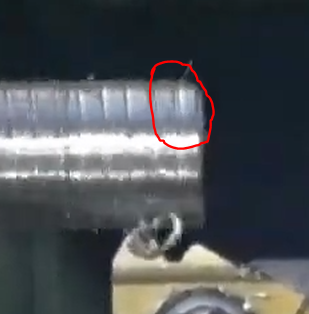
Two rotations later, and you can see a second groove forming to the right of the first pass... but it isn't much deeper.
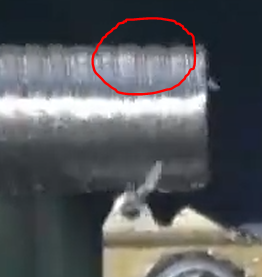
Third pass, and now there's a 3rd groove - also to the right. And also isn't much deeper. Maybe deflection, but I didn't see the stock wobbling a ton or climbing the insert. Almost like it isn't going any deeper each pass, just shifting to the right.
In addition to running a no-Q value test, it might be helpful to set up a halscope with the Z-axis position and the spindle index signal. Try to see exactly where the Z-axis is when the index signal is triggered, and does the Z-axis then start moving immediately?
My earlier suspicion about the start point being the same may not be accurate - hard to spot 0.1mm-0.2mm shift of the insert on video.
Finally, you could put an ink pen in the tool holder and run a series of 3 to 4 G33 moves, using the pen to draw a thread. Since "The G76 canned cycle is based on the G33 Spindle Synchronized Motion", multiple G33 passes should help you determine if the synchronization start point is exactly the same place without any other motion distractions.
Try it at different spindle speeds - but use the same speed for each set of repetitions. If you want to test my claims about the bug, run a 4-pass test, but increase the spindle speed by 100-200rpm each pass.
If the start point is the same every time during G33 (same spindle speed) - but not during G76 - you've got a threading-specific problem.
If it's not the same, you've got a more fundamental synchronization problem... mechanical or LCNC configuration. Or you may be encountering the bug I mentioned earlier from a different direction.
Start of pass 2, chip is forming on the right of the insert:
Two rotations later, and you can see a second groove forming to the right of the first pass... but it isn't much deeper.
Third pass, and now there's a 3rd groove - also to the right. And also isn't much deeper. Maybe deflection, but I didn't see the stock wobbling a ton or climbing the insert. Almost like it isn't going any deeper each pass, just shifting to the right.
In addition to running a no-Q value test, it might be helpful to set up a halscope with the Z-axis position and the spindle index signal. Try to see exactly where the Z-axis is when the index signal is triggered, and does the Z-axis then start moving immediately?
My earlier suspicion about the start point being the same may not be accurate - hard to spot 0.1mm-0.2mm shift of the insert on video.
Finally, you could put an ink pen in the tool holder and run a series of 3 to 4 G33 moves, using the pen to draw a thread. Since "The G76 canned cycle is based on the G33 Spindle Synchronized Motion", multiple G33 passes should help you determine if the synchronization start point is exactly the same place without any other motion distractions.
Try it at different spindle speeds - but use the same speed for each set of repetitions. If you want to test my claims about the bug, run a 4-pass test, but increase the spindle speed by 100-200rpm each pass.
If the start point is the same every time during G33 (same spindle speed) - but not during G76 - you've got a threading-specific problem.
If it's not the same, you've got a more fundamental synchronization problem... mechanical or LCNC configuration. Or you may be encountering the bug I mentioned earlier from a different direction.
Attachments:
The following user(s) said Thank You: RotarySMP, Dudelbert
Please Log in or Create an account to join the conversation.
Moderators: piasdom
Time to create page: 1.119 seconds