7i96S card arrived what setup is recomended
- PCW
-

- Offline
- Moderator
-

Less
More
- Posts: 17919
- Thank you received: 5247
28 Apr 2026 14:24 #346009
by PCW
Replied by PCW on topic 7i96S card arrived what setup is recomended
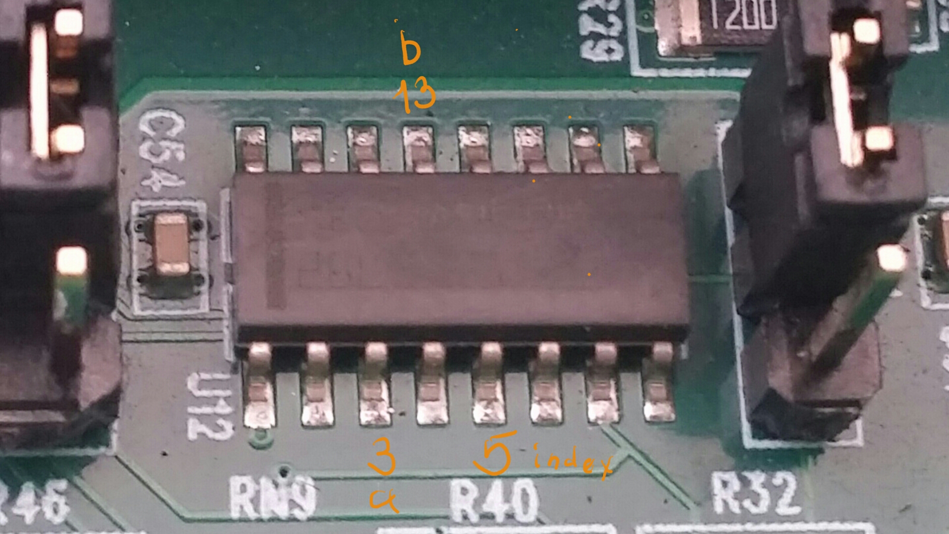
In one picture you have the encoder inputs connected, this may affect test results.
Here is the encoder input circuit, you can check if the 26LS32 is faulty by seeing of the
outputs follow the input state. (the outputs are inverted from the TTL input levels)
Here is the encoder input circuit, you can check if the 26LS32 is faulty by seeing of the
outputs follow the input state. (the outputs are inverted from the TTL input levels)
Attachments:
Please Log in or Create an account to join the conversation.
- xenon-alien
-

- Offline
- Premium Member
-

Less
More
- Posts: 157
- Thank you received: 4
28 Apr 2026 19:03 #346019
by xenon-alien
Thanks for the hint how to check the 26LS32. Tomorrow I will try.
You think, maybe it can be the inputs to the main microchip if the 26LS32 works correctly?
Replied by xenon-alien on topic 7i96S card arrived what setup is recomended
Not really understand, but the result is the same, as it was with the TTL encoder.In one picture you have the encoder inputs connected, this may affect test results.
Here is the encoder input circuit, you can check if the 26LS32 is faulty by seeing of the
outputs follow the input state. (the outputs are inverted from the TTL input levels)
Thanks for the hint how to check the 26LS32. Tomorrow I will try.
You think, maybe it can be the inputs to the main microchip if the 26LS32 works correctly?
Please Log in or Create an account to join the conversation.
- PCW
-
- Offline
- Moderator
-
Less
More
- Posts: 17919
- Thank you received: 5247
28 Apr 2026 19:18 #346020
by PCW
Replied by PCW on topic 7i96S card arrived what setup is recomended
You think, maybe it can be the inputs to the main microchip if the 26LS32 works correctly?
It's quite unlikely that the FPGA has been damaged, much more likely that the 26LS32 has been.
Also the 26LS32 does not connect to the FPGA directly but rather through U13 (74CBT16211
level shifter) If U13 was damaged (by say a mistake in P1 connections) this could cause an
encoder issue as U13 is shared by the encoder interface and the P1 parallel expansion port.
You can do a quick check of U13 with mesaflash (assuming P1 is unconnected):
mesaflash --device ethernet --address [card-address] --rpo 0x1008
This should respond with: 0001FFFF (the all high open circuit port data for the parallel
expansion port = P1). Damaged U13 I/O pins that connect to P1 will typically be stuck low.
Please Log in or Create an account to join the conversation.
- xenon-alien
-
- Offline
- Premium Member
-
Less
More
- Posts: 157
- Thank you received: 4
29 Apr 2026 05:01 #346030
by xenon-alien
On the table there wont be a phisical connection to P1, just 5v supply.
Here it is (both has the same respond):
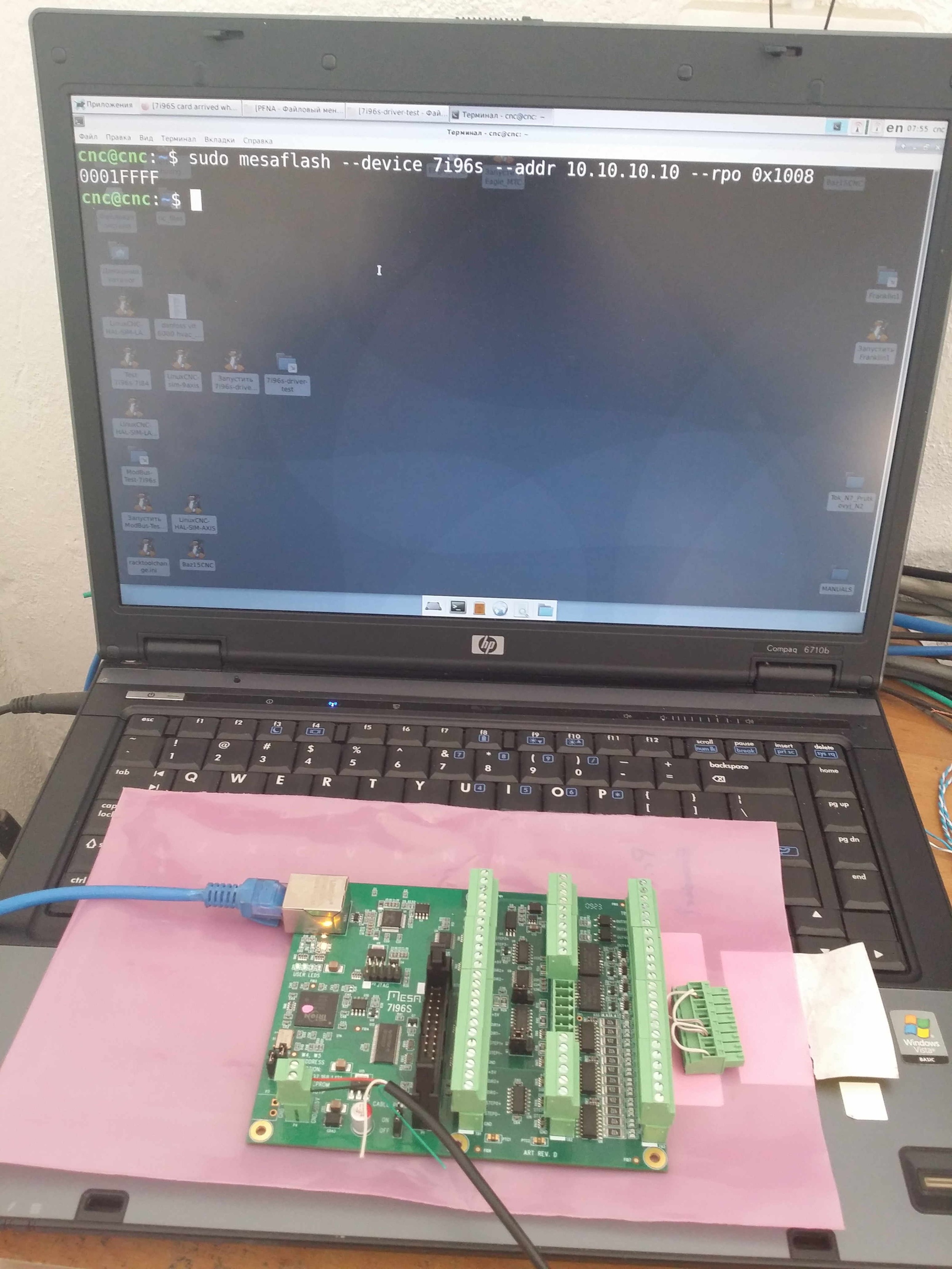
Replied by xenon-alien on topic 7i96S card arrived what setup is recomended
To the P1 just connected the axis indexes (1-5 pins - you did the firmware to me) 50-100Om through resistor as you wrote me (5v supply GND to the driver and from the driver back to the P1 through a 100Om resistor)Also the 26LS32 does not connect to the FPGA directly but rather through U13 (74CBT16211
level shifter) If U13 was damaged (by say a mistake in P1 connections) this could cause an
encoder issue as U13 is shared by the encoder interface and the P1 parallel expansion port.
You can do a quick check of U13 with mesaflash (assuming P1 is unconnected):
mesaflash --device ethernet --address [card-address] --rpo 0x1008
This should respond with: 0001FFFF (the all high open circuit port data for the parallel
expansion port = P1). Damaged U13 I/O pins that connect to P1 will typically be stuck low.
On the table there wont be a phisical connection to P1, just 5v supply.
Here it is (both has the same respond):
Attachments:
Please Log in or Create an account to join the conversation.
- tommylight
-

- Away
- Moderator
-
Less
More
- Posts: 21632
- Thank you received: 7387
29 Apr 2026 05:06 #346031
by tommylight
Replied by tommylight on topic 7i96S card arrived what setup is recomended
If that is the same result for both cards, seems both are OK>
Check wiring and voltage at the Mesa inputs, might be to low to trigger.
Check wiring and voltage at the Mesa inputs, might be to low to trigger.
Please Log in or Create an account to join the conversation.
- xenon-alien
-
- Offline
- Premium Member
-
Less
More
- Posts: 157
- Thank you received: 4
29 Apr 2026 07:33 #346032
by xenon-alien
Can I force 5v to this pins (via wire from 5v supply from the stepper pins) to see in hal show will it change or not?
Replied by xenon-alien on topic 7i96S card arrived what setup is recomended
If the pins are correct (3. 5. 13.), there are no movement on the not working channels.Here is the encoder input circuit, you can check if the 26LS32 is faulty by seeing of the
outputs follow the input state. (the outputs are inverted from the TTL input levels)
Can I force 5v to this pins (via wire from 5v supply from the stepper pins) to see in hal show will it change or not?
Attachments:
Please Log in or Create an account to join the conversation.
- PCW
-
- Offline
- Moderator
-
Less
More
- Posts: 17919
- Thank you received: 5247
30 Apr 2026 13:27 #346055
by PCW
Replied by PCW on topic 7i96S card arrived what setup is recomended
You could, but you risk more damage if you accidentally connect the 5V to a 3.3V signal.
Most likely the inputs of the 26LS32 has been damaged so the chip needs to be replaced.
This takes care and protection of the nearby plastic connectors with some kind of
insulation from the hot air gun heat (I typically use some paper sticky labels on
the green connectors)
Most likely the inputs of the 26LS32 has been damaged so the chip needs to be replaced.
This takes care and protection of the nearby plastic connectors with some kind of
insulation from the hot air gun heat (I typically use some paper sticky labels on
the green connectors)
The following user(s) said Thank You: xenon-alien
Please Log in or Create an account to join the conversation.
- xenon-alien
-
- Offline
- Premium Member
-
Less
More
- Posts: 157
- Thank you received: 4
01 May 2026 04:55 #346072
by xenon-alien
I'm watching videos with notebook repairs, so i saw there how they protect the plastic parts from melting.
I hope i wont fail.
Replied by xenon-alien on topic 7i96S card arrived what setup is recomended
OK. I won't risk.You could, but you risk more damage if you accidentally connect the 5V to a 3.3V signal.
Most likely the inputs of the 26LS32 has been damaged so the chip needs to be replaced.
This takes care and protection of the nearby plastic connectors with some kind of
insulation from the hot air gun heat (I typically use some paper sticky labels on
the green connectors)
I'm watching videos with notebook repairs, so i saw there how they protect the plastic parts from melting.
I hope i wont fail.
Please Log in or Create an account to join the conversation.
Moderators: PCW, jmelson
Time to create page: 0.208 seconds