Light Machine Corp. Benchman XTr (retrofit)
- project-pegasus
-

- Visitor
-

24 Oct 2018 04:18 #119314
by project-pegasus
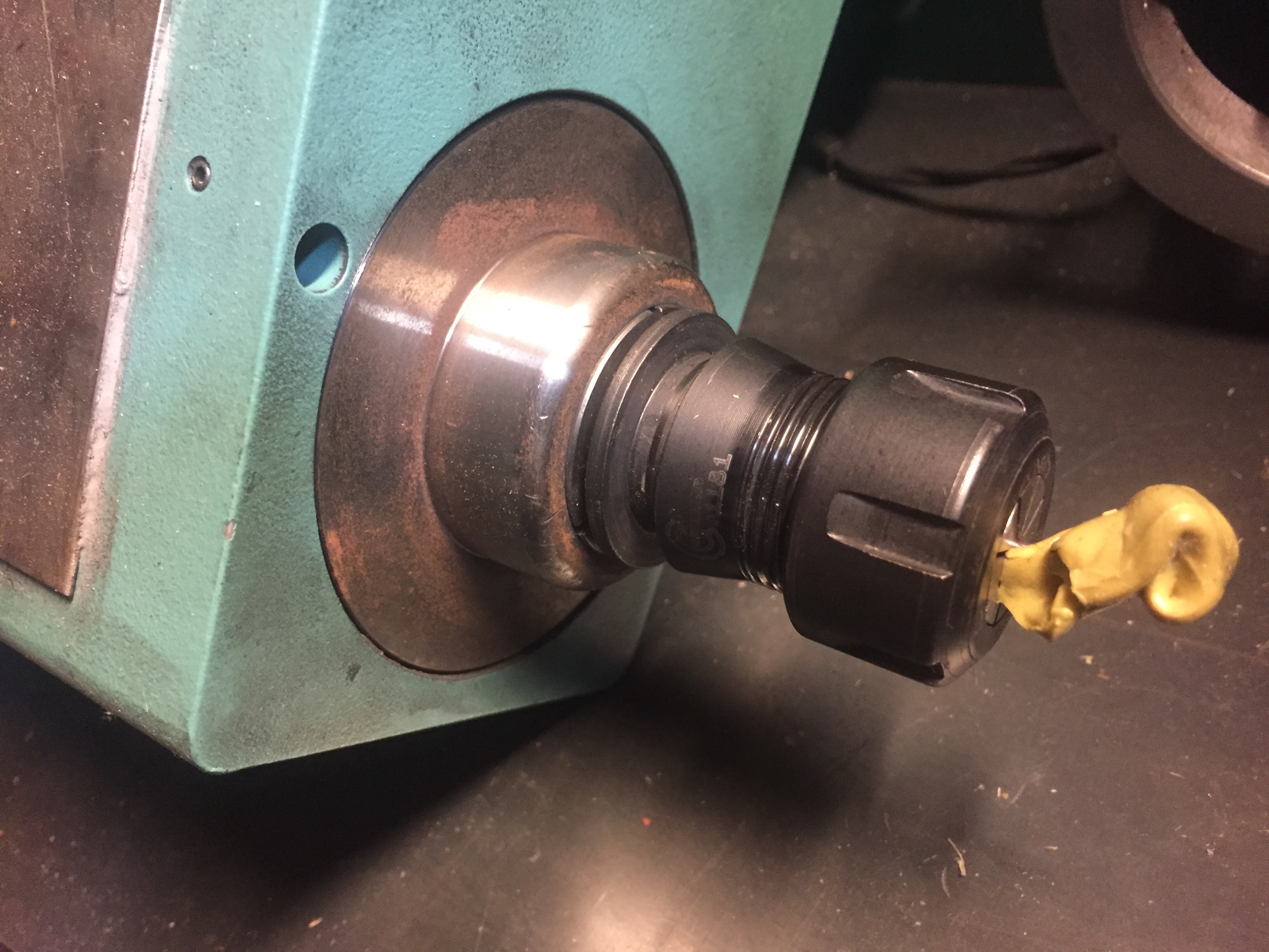
Replied by project-pegasus on topic Light Machine Corp. Benchman XTr (retrofit) Spindle Sensor Question
Here’s mine:
Please Log in or Create an account to join the conversation.
- steve_a
- Offline
- Senior Member
-

Less
More
- Posts: 75
- Thank you received: 2
24 Oct 2018 04:46 #119318
by steve_a
Replied by steve_a on topic Light Machine Corp. Benchman XTr (retrofit) Spindle Sensor Question
Wow! Thank you project_pegasus... yours are totally different than mine! I always assumed they were all the same but I'm guessing you do not have the automatic tool changer. My tool holders have some funky indexing slots and that makes some kind of difference. For me it means the tool must be in a very particular orientation to receive and deliver to the tool carousel. I really appreciate you showing me that. It answers a lot of questions!
Please Log in or Create an account to join the conversation.
- x-Intelitek Engineer
- Offline
- Premium Member
-

Less
More
- Posts: 113
- Thank you received: 22
24 Oct 2018 17:15 #119350
by x-Intelitek Engineer
Replied by x-Intelitek Engineer on topic Light Machine Corp. Benchman XTr (retrofit) Spindle Sensor Question
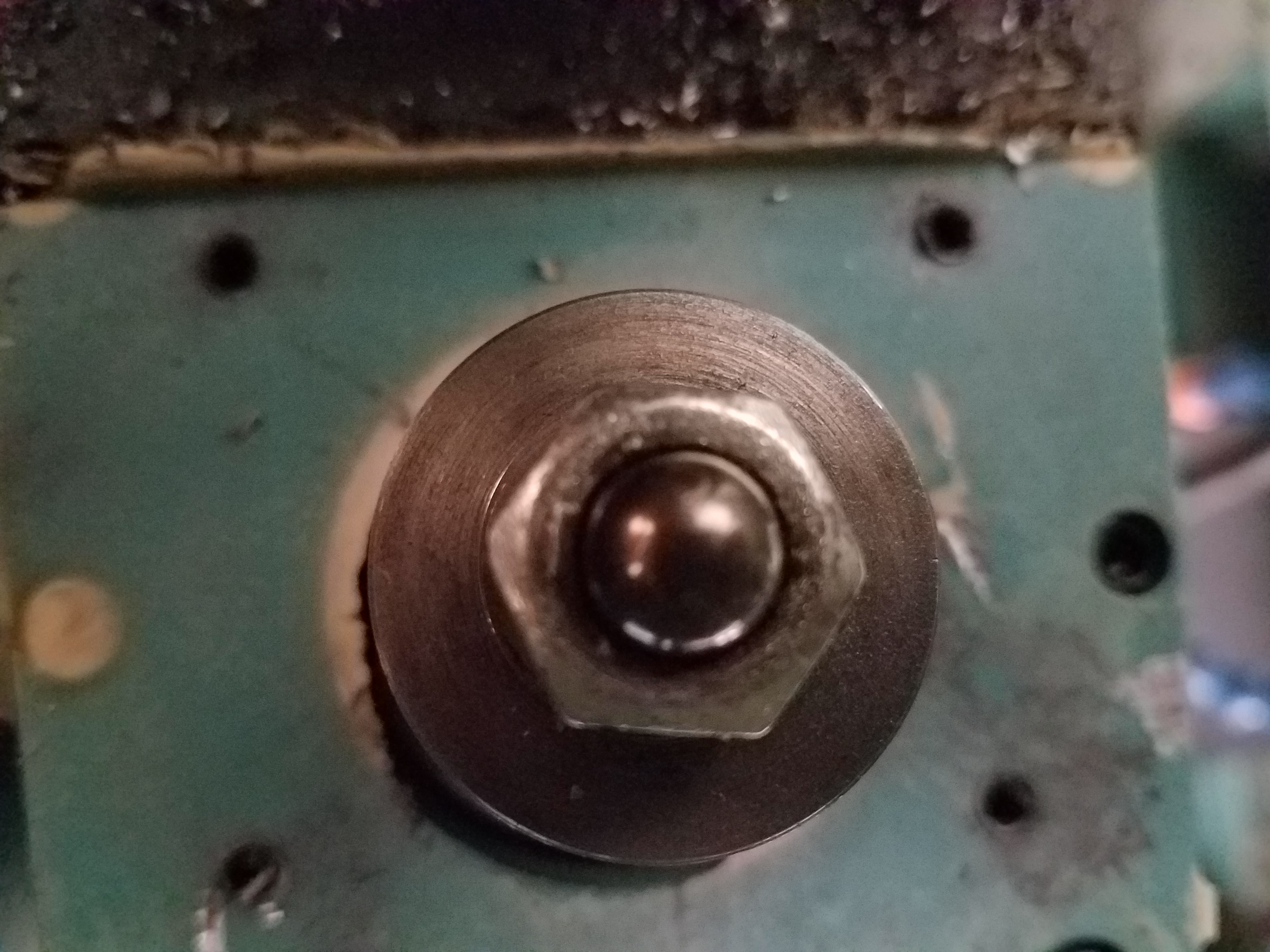
Your spindle is the version that takes a custom straight shank toolholder. The hole you see is for a screw that secures the toolholder so that it cannot spin if the workload becomes heavy. The index for the spindle is inside the head of the spindle. I believe the index is a flat on the shaft. I wish I remember more, but my discipline is electrical. Intelitek should be able to help you. Are you still running the Intelitek S/W or moving to something else.
Please Log in or Create an account to join the conversation.
- steve_a
- Offline
- Senior Member
-
Less
More
- Posts: 75
- Thank you received: 2
26 Oct 2018 06:34 #119430
by steve_a
Replied by steve_a on topic Light Machine Corp. Benchman XTr (retrofit) Spindle Sensor Question
OK, I dug into the bowels of the spindle head to try to determine why the sensor was not reading anything. I removed the sensor and examined the spindle it was closest to. I bench tested the sensor and found that it did not react to a ferric metal mass. For fun I tried a magnet and it DID react to that. However the spindle parts show no magnetism at all. Is there any possibility a magnet was at some point glued to the washer? Non of my findings make sense.
Please Log in or Create an account to join the conversation.
- andypugh
-

- Offline
- Moderator
-

Less
More
- Posts: 19861
- Thank you received: 4636
26 Oct 2018 11:58 - 26 Oct 2018 11:59 #119439
by andypugh
Replied by andypugh on topic Light Machine Corp. Benchman XTr (retrofit) Spindle Sensor Question
Possibly it is a sensor similar to this one in design:
www.allegromicro.com/~/media/Files/Datas...A9D70FB340EE44BA4F1E
And the internal magnet has been destroyed by heat.
It is probably not worth worrying about if the thread is M8 x 1 or another of the common proximity sensor sizes, just buy an inductive sensor from eBay that _will_ detect the spindle.
[edit] But make sure that you won't run up against any frequency / response-time limits.
Last edit: 26 Oct 2018 11:59 by andypugh.
The following user(s) said Thank You: steve_a
Please Log in or Create an account to join the conversation.
- x-Intelitek Engineer
- Offline
- Premium Member
-
Less
More
- Posts: 113
- Thank you received: 22
26 Oct 2018 12:25 #119442
by x-Intelitek Engineer
Replied by x-Intelitek Engineer on topic Light Machine Corp. Benchman XTr (retrofit) Spindle Sensor Question
Thinking about it some more, I believe that is the drawbar sensor and not the spindle index sensor. The drawbar sensor is to ensure that the spindle cannot turn while the drawbar is open. The spindle index sensor is part of the spindle encoder connection to the speed control.
The following user(s) said Thank You: steve_a
Please Log in or Create an account to join the conversation.
- steve_a
- Offline
- Senior Member
-
Less
More
- Posts: 75
- Thank you received: 2
26 Oct 2018 21:59 #119491
by steve_a
Replied by steve_a on topic Light Machine Corp. Benchman XTr (retrofit) Spindle Sensor Question
OK, That makes all kinds of sense now! That being said I think the encoder is attached to the back of the motor so that means the ratio must be 1:1 to be able to accurately index the spindle. I'll have to see if I can access the wires and throw a meter on them. Wow this is going to be a complicated series of moves. Well at least I have a direction to try. THANKS ALL!
Please Log in or Create an account to join the conversation.
- x-Intelitek Engineer
- Offline
- Premium Member
-
Less
More
- Posts: 113
- Thank you received: 22
29 Oct 2018 13:22 #119591
by x-Intelitek Engineer
Replied by x-Intelitek Engineer on topic Light Machine Corp. Benchman XTr (retrofit) Spindle Sensor Question
It may be 1:1, if your spindle is 5K it is 1:1, if you have a 7.5K spindle, it is belt driven and it becomes 1.5:1.
Please Log in or Create an account to join the conversation.
- steve_a
- Offline
- Senior Member
-
Less
More
- Posts: 75
- Thank you received: 2
29 Oct 2018 21:50 #119626
by steve_a
Replied by steve_a on topic Light Machine Corp. Benchman XTr (retrofit) Spindle Sensor Question
That's really interesting, but that would mean 7.5K cannot have a tool changer unless it has a different method to index the spindle. Were there toll changing models that ran at 7.5K?
Please Log in or Create an account to join the conversation.
- x-Intelitek Engineer
- Offline
- Premium Member
-
Less
More
- Posts: 113
- Thank you received: 22
30 Oct 2018 15:52 #119645
by x-Intelitek Engineer
Replied by x-Intelitek Engineer on topic Light Machine Corp. Benchman XTr (retrofit) Spindle Sensor Question
Steve, you are correct. The 7.5K spindle used an external prox sensor to create the spindle home signal. Spindle Home is not spindle in position to do a toolchange, that is an offset from spindle home. The spindle home sensor is wired to J24 in a single control board Benchman, or J528 in the original multi-board configuration. I do not recall exactly what the sensor was detecting (flat or flag) on the spindle head.
Please Log in or Create an account to join the conversation.
Time to create page: 0.438 seconds