Light Machine Corp. Benchman XTr (retrofit)
- project-pegasus
-

- Visitor
-

28 Aug 2019 22:48 #143497
by project-pegasus
Replied by project-pegasus on topic Light Machine Corp. Benchman XTr (retrofit)
X-Intelitek Engineer,
Thank you again for your help. I have been able to figure out most of the wiring based on the schematics you gave me but I still have a couple of questions. On the larger orange connector with 12 positions I've been able to figure out that position 1(Common) goes to J109-18, position 2 (Enable) goes to J109-15, position 5 (Vssc) goes to J109-2, and Hall A,B,C correspond to J109-24,25,26. But on position 3 you list as (Brake) I can't find a corresponding J109 pin in the schematics, similarly with position 4 (Fwd/Rev) and position 7 (NC). Would those terms correspond to other terminology in the wiring schematics, I noticed you listed "Sig In" for position 6 on the orange connector but I think that it is called "V_SPDL_CMD" in the schematics at J109-2? And do you have any idea what wires from J109 would go to the spindle's vref and common, pins 11 and 12 on the orange connector. Thanks again.
Thank you again for your help. I have been able to figure out most of the wiring based on the schematics you gave me but I still have a couple of questions. On the larger orange connector with 12 positions I've been able to figure out that position 1(Common) goes to J109-18, position 2 (Enable) goes to J109-15, position 5 (Vssc) goes to J109-2, and Hall A,B,C correspond to J109-24,25,26. But on position 3 you list as (Brake) I can't find a corresponding J109 pin in the schematics, similarly with position 4 (Fwd/Rev) and position 7 (NC). Would those terms correspond to other terminology in the wiring schematics, I noticed you listed "Sig In" for position 6 on the orange connector but I think that it is called "V_SPDL_CMD" in the schematics at J109-2? And do you have any idea what wires from J109 would go to the spindle's vref and common, pins 11 and 12 on the orange connector. Thanks again.
Please Log in or Create an account to join the conversation.
- x-Intelitek Engineer
- Offline
- Premium Member
-

Less
More
- Posts: 113
- Thank you received: 22
30 Aug 2019 18:44 #143682
by x-Intelitek Engineer
Replied by x-Intelitek Engineer on topic Light Machine Corp. Benchman XTr (retrofit)
Position 1 goes to J109-18 - Correct
Position 2 goes to J109-15 - Correct
Position 5 (Vssc) should go to J109-12 not J109-2
Hall A,B,C go to J109-24,25,26 - Correct
Position 3 (Brake) should go to J109-4 I believe.
J109-4 and J109-15 should be inverted from each other. In other words: Enable=no Brake, Disable=Brake.
You should to check the polarity.
Position 4 (FWD/REV) should go to J109-7.
J109-7 and J109-10 should be inverted from each other. In other words: FWD = not REV, Not FWD = REV.
You should to check polarity.
Position 7 (NC) is No Connect - Do not connect anything to this location
Position 6 is called "SIG IN" by the speed control, it is called "V_SPDL_CMD" on the PCB. It is J109-2.
J109 should not connect to the Vref and Common (pins11 & 12) those only go to the spindle to power the internal hall circuitry.
I think that is correct. 95%+ confidence level.
Please Log in or Create an account to join the conversation.
- project-pegasus
-
- Visitor
-
30 Aug 2019 19:21 #143686
by project-pegasus
Replied by project-pegasus on topic Light Machine Corp. Benchman XTr (retrofit)
Thank you, X.
We will get this figured out!
We will get this figured out!
Please Log in or Create an account to join the conversation.
- SOSMachining
- Offline
- New Member
-

Less
More
- Posts: 7
- Thank you received: 1
28 Sep 2019 14:21 #146491
by SOSMachining
Replied by SOSMachining on topic Light Machine Corp. Benchman XTr (retrofit)
Hey Guys,
Newbie here but I love this forum. A few years ago I stumbled across a craigslist auction for two of these machines and have been tinkering with them ever since. After a couple of new parts to the old PC and some practice learning g-code on Youtube, I've been able to sling pretty steady aluminum chips from one of the machines so it's been a pretty cool project. I've attached a couple pictures of the machines with some upgraded aquarium lights below.
The one issue that I have is that it seems like my tool holders are struggling to repeatably get all the way up inside the drawbar. I've tried to do some aligning and re-homing of the ATC following the instructions in the manual but I still see anywhere between 0.004" and 0.020" variation between tool changes. I'll probably need to do some heavier dis-assembly and re-assembly of the ATC one of these weeks but I haven't made it there yet. Recently I've become pretty curious about the possibility of adding a tool-length offset probe inside the machine to verify the offset after a tool change but I'm not sure if my machine has the right main board to support a probe.
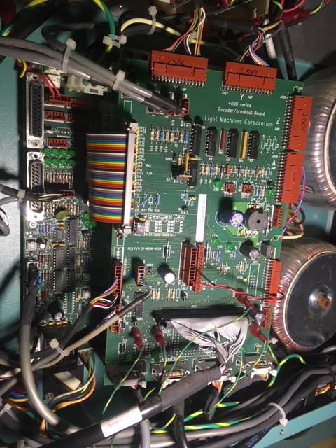
I've attached a couple picture that show the setup inside my control panel because it looks quite a bit different than the other posts in this forum. It looks like my main board on this machine is very similar to that of the ProLight machines and I have ASI motion controller card inside the PC rather than and PCI cards.
In looking I definitely don't have the wiring for the probe connector on the back of the front panel inside the machine like the probe-offset manual says I should. I can attach more pictures if necessary, but I guess my question is, does anyone know if this machine is capable of using a tool-length-offset probe, and if so, which pins input the signal from the probe?
Thanks, guys! This forum has been a huge help in getting my machines up and running!
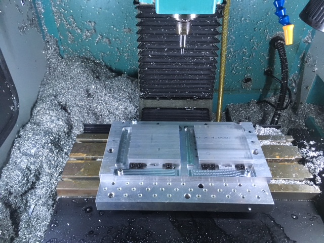
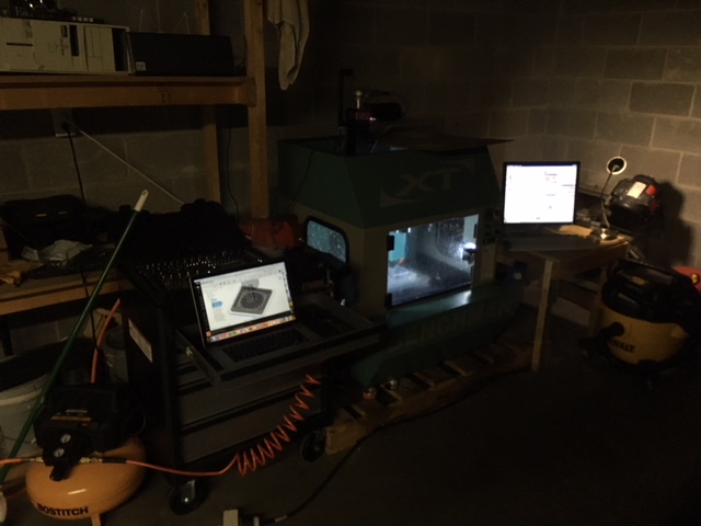

Newbie here but I love this forum. A few years ago I stumbled across a craigslist auction for two of these machines and have been tinkering with them ever since. After a couple of new parts to the old PC and some practice learning g-code on Youtube, I've been able to sling pretty steady aluminum chips from one of the machines so it's been a pretty cool project. I've attached a couple pictures of the machines with some upgraded aquarium lights below.
The one issue that I have is that it seems like my tool holders are struggling to repeatably get all the way up inside the drawbar. I've tried to do some aligning and re-homing of the ATC following the instructions in the manual but I still see anywhere between 0.004" and 0.020" variation between tool changes. I'll probably need to do some heavier dis-assembly and re-assembly of the ATC one of these weeks but I haven't made it there yet. Recently I've become pretty curious about the possibility of adding a tool-length offset probe inside the machine to verify the offset after a tool change but I'm not sure if my machine has the right main board to support a probe.
I've attached a couple picture that show the setup inside my control panel because it looks quite a bit different than the other posts in this forum. It looks like my main board on this machine is very similar to that of the ProLight machines and I have ASI motion controller card inside the PC rather than and PCI cards.
In looking I definitely don't have the wiring for the probe connector on the back of the front panel inside the machine like the probe-offset manual says I should. I can attach more pictures if necessary, but I guess my question is, does anyone know if this machine is capable of using a tool-length-offset probe, and if so, which pins input the signal from the probe?
Thanks, guys! This forum has been a huge help in getting my machines up and running!
Attachments:
Please Log in or Create an account to join the conversation.
- project-pegasus
-
- Visitor
-
28 Sep 2019 20:16 - 28 Sep 2019 20:20 #146503
by project-pegasus
Replied by project-pegasus on topic Light Machine Corp. Benchman XTr (retrofit)
I've never been able to get my ATC to work, so I can't offer any help there. I have the same boards you do, and I've never looked into setting up the probe. I like your LED lighting inside the enclosure. Did your XT come with a coolant pump? Mine didn't and I'm thinking about putting one in. Do these machines have some kind of integrated sump in the bottom? Is the pump just located in the corner of the enclosure?
Last edit: 28 Sep 2019 20:20 by project-pegasus. Reason: Info
Please Log in or Create an account to join the conversation.
- x-Intelitek Engineer
- Offline
- Premium Member
-
Less
More
- Posts: 113
- Thank you received: 22
30 Sep 2019 17:38 #146729
by x-Intelitek Engineer
Replied by x-Intelitek Engineer on topic Light Machine Corp. Benchman XTr (retrofit)
Your hardware can support the tool probe, but getting the software to use it is the issue. As I recall, it was an option that was enabled in the software if you paid for it. I have no idea on how to enable it. But the hardware is easy. A simple switch closure on J530 along with a jumper on the same connector will provide the asynchronous interrupt signal to the nextmove card to immediately capture the X, Y, & Z positions. But without the appropriate software, I'm not sure how you can use that information. It is more difficult to get the signal through the backpanel without compromising the "watertightness" of the enclosure. We had chosen a location in the lower rear that was potentially right in the path of the flood coolant spray so we had to have "watertight" connections. I can provide more electrical information if required, but you will need to deal with the software side.
Please Log in or Create an account to join the conversation.
- x-Intelitek Engineer
- Offline
- Premium Member
-
Less
More
- Posts: 113
- Thank you received: 22
30 Sep 2019 17:42 #146730
by x-Intelitek Engineer
Replied by x-Intelitek Engineer on topic Light Machine Corp. Benchman XTr (retrofit)
Pegasus,
If your machine was equipped with a coolant pump, there were some perforated panels that sat on the large rails below the polymer granite frame. The area below these panels became the sump. A Little Giant pump was located in this area and would supply the coolant to the flexible fittings for aiming. However, I also believe that the base enclosure may have been custom for the flood machines owing to the fact that watertightness was required. Look at the inside lower corners of the enclosure and see if they are welded beyond simple spot-welds.
If your machine was equipped with a coolant pump, there were some perforated panels that sat on the large rails below the polymer granite frame. The area below these panels became the sump. A Little Giant pump was located in this area and would supply the coolant to the flexible fittings for aiming. However, I also believe that the base enclosure may have been custom for the flood machines owing to the fact that watertightness was required. Look at the inside lower corners of the enclosure and see if they are welded beyond simple spot-welds.
Please Log in or Create an account to join the conversation.
- SOSMachining
- Offline
- New Member
-
Less
More
- Posts: 7
- Thank you received: 1
05 Oct 2019 02:06 - 05 Oct 2019 02:08 #147153
by SOSMachining
Replied by SOSMachining on topic Light Machine Corp. Benchman XTr (retrofit)
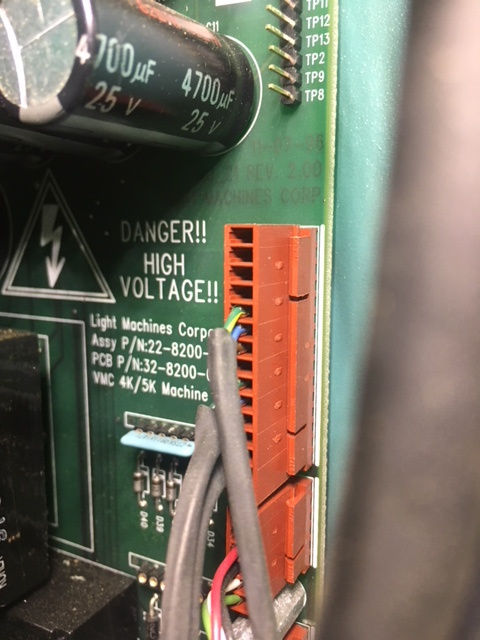
Awesome! Thank you for the response. It looks like the J530 pin is right on the front of the main board but it's got 7 pins. Do you have any pinout schematics on what each of those 7 pins does? Also do you happen to remember the style of connector used on the board? I'd like to try wiring up a test to see if the pins are functional.
In digging through the Intellitek website it looks like the Benchman software is on there and available for download but I'm unable to install it in a way that allows it to communicate through the ASI slot. I'm thinking that I may try installing Windows NT on an extra hard drive and trying to boot my computer with Windows NT to install the software. My thinking is that maybe if I'm able to use a fresh download of the NT software that I can enable the probe functionality to test the pins since my Windows 98 doesn't seem to want to let the fresh install talk through the ASI slot.
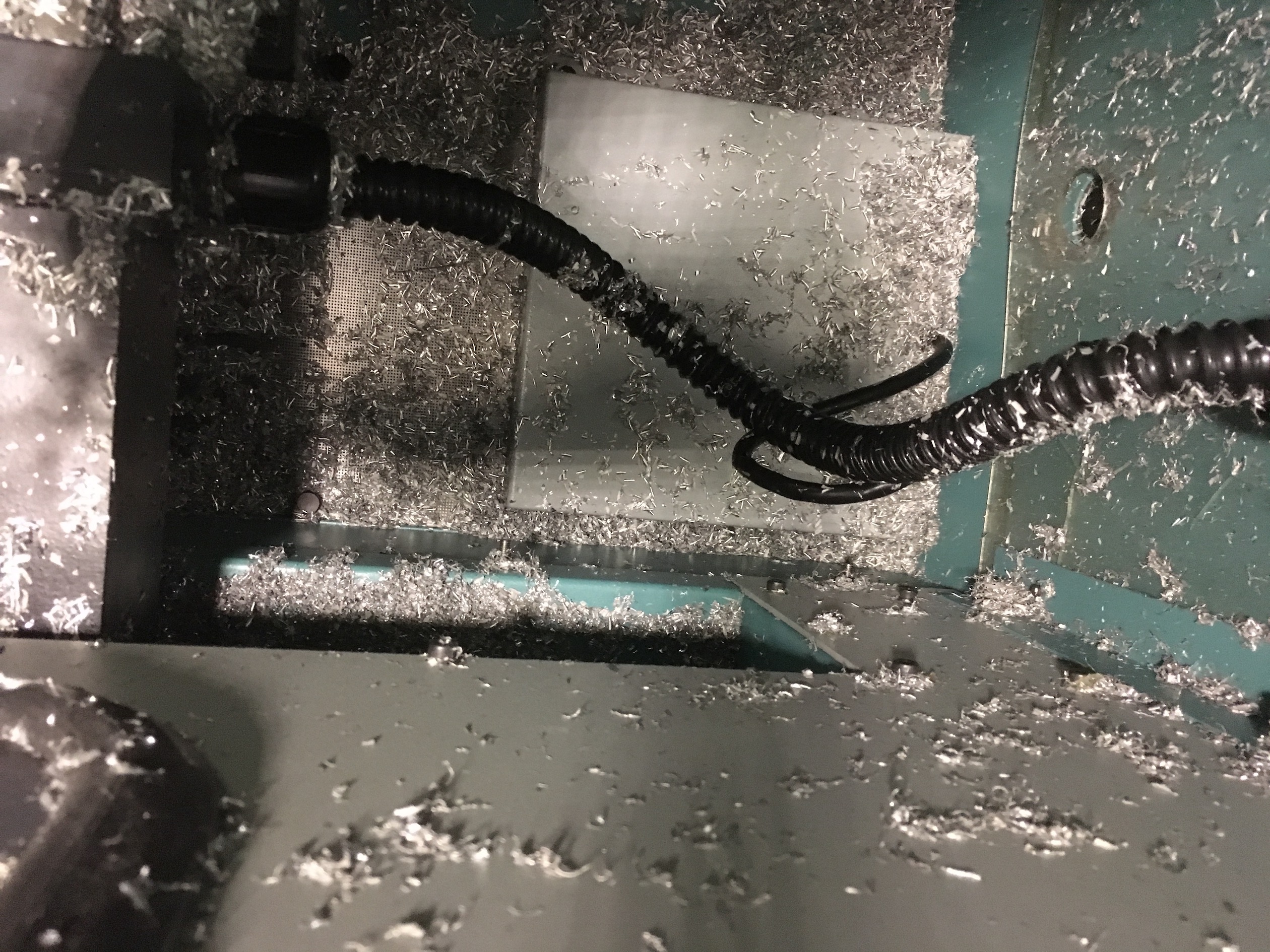
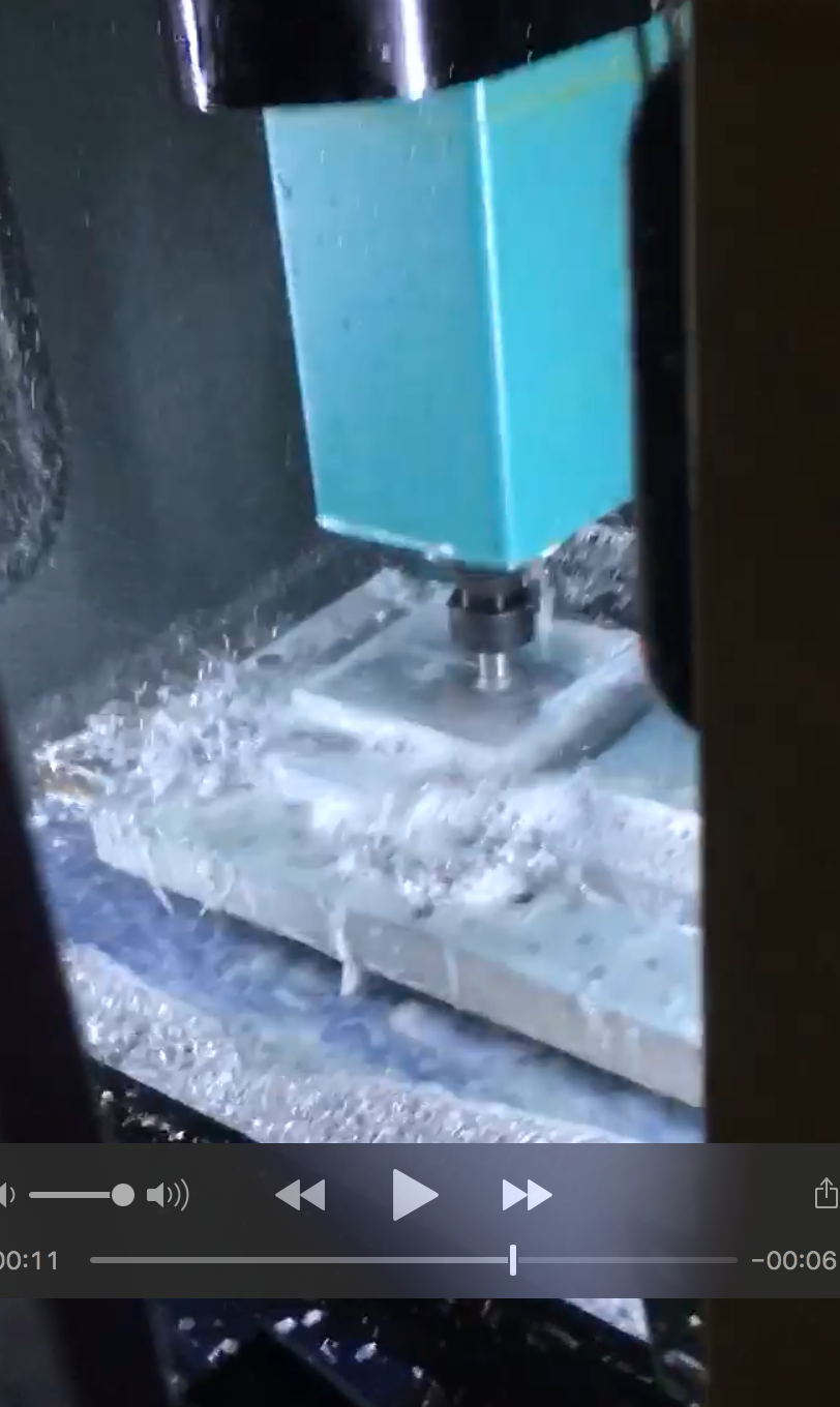
I've attached a photo of the perforated material in the bottom of my machine above where the coolant pump is. It looks like the coolant pump is wired into J107 on the main board but I think if I had the opportunity to rewire I think I'd wire it separately from the machine controls because my machine sometimes faults out mid-cycle because of coolant pump issues. I haven't been able to track down exactly whats causing the issue so it's kind of a hassle some days. I've also attached a picture of a 2" face mill doing some passes in aluminum with the coolant on. I can see why the "waterproofness" of the panel was a concern as the coolant flies everywhere when she's on!
Thanks guys!
In digging through the Intellitek website it looks like the Benchman software is on there and available for download but I'm unable to install it in a way that allows it to communicate through the ASI slot. I'm thinking that I may try installing Windows NT on an extra hard drive and trying to boot my computer with Windows NT to install the software. My thinking is that maybe if I'm able to use a fresh download of the NT software that I can enable the probe functionality to test the pins since my Windows 98 doesn't seem to want to let the fresh install talk through the ASI slot.
I've attached a photo of the perforated material in the bottom of my machine above where the coolant pump is. It looks like the coolant pump is wired into J107 on the main board but I think if I had the opportunity to rewire I think I'd wire it separately from the machine controls because my machine sometimes faults out mid-cycle because of coolant pump issues. I haven't been able to track down exactly whats causing the issue so it's kind of a hassle some days. I've also attached a picture of a 2" face mill doing some passes in aluminum with the coolant on. I can see why the "waterproofness" of the panel was a concern as the coolant flies everywhere when she's on!
Thanks guys!
Attachments:
Last edit: 05 Oct 2019 02:08 by SOSMachining.
Please Log in or Create an account to join the conversation.
- x-Intelitek Engineer
- Offline
- Premium Member
-
Less
More
- Posts: 113
- Thank you received: 22
07 Oct 2019 17:27 #147353
by x-Intelitek Engineer
Replied by x-Intelitek Engineer on topic Light Machine Corp. Benchman XTr (retrofit)
SOS:
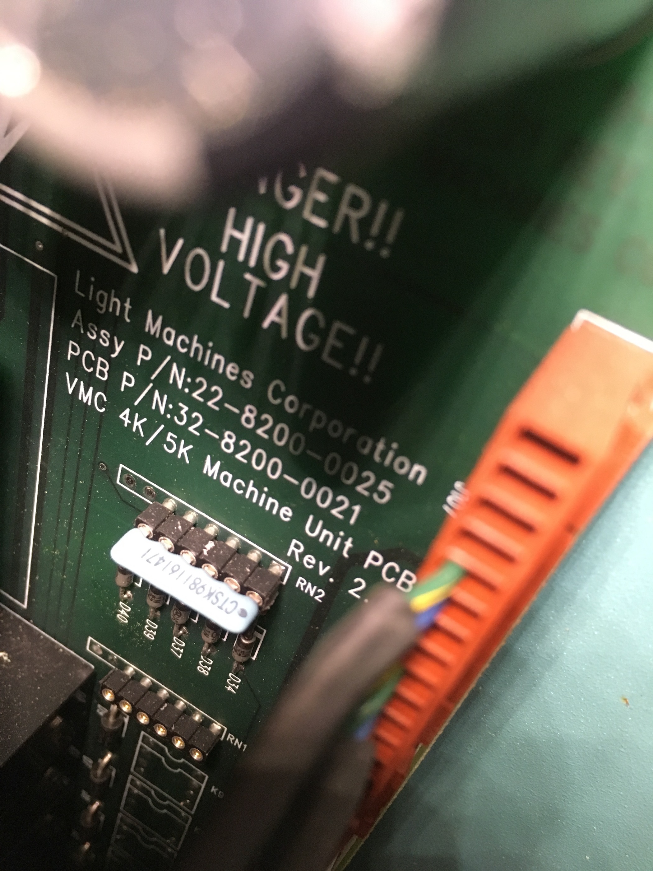
Connector is Molex: 22-01-2077
Contact is Molex: 08-55-0105
Both available thru Digikey.
The circuitry for the probe on your machine is attached.
Try running the pump direct to the wall instead of through the machine.and see if the machine faults go away.
Let me know if you need further documentation or information.
Please Log in or Create an account to join the conversation.
- project-pegasus
-
- Visitor
-
23 Oct 2019 22:01 #148635
by project-pegasus
Replied by project-pegasus on topic Light Machine Corp. Benchman XTr (retrofit)
I pulled up the panels on my XT and it looks like the sump beneath the table is water tight (there's a drain plug at the back of the machine). I guess the machines with the coolant pump option got screen floors and those like mine got sheet metal floors. Unfortunately, the previous owners of this machine used it to mill carbon electrodes and it was full of carbon dust when I got it. I had a spindle coolant leak a few months ago and a large quantity of coolant ended up in the sump. So when I pulled those panels up the other day I discovered a whole lot of black sludge down there.
Does anybody know what model of Little Giant pump was used on the XT. The sump is only about 4 inches deep.
Does anybody know what model of Little Giant pump was used on the XT. The sump is only about 4 inches deep.
Please Log in or Create an account to join the conversation.
Time to create page: 4.774 seconds