Crusader II retrofit
- jamby
- Offline
- Elite Member
-

Less
More
- Posts: 235
- Thank you received: 6
19 Mar 2016 14:43 #71896
by jamby
Replied by jamby on topic Crusader II retrofit
Could this ebay dc-dc boost converter be used to provide 24v power for the E-stop / limit circuit?
www.ebay.com/itm/DC-DC-boost-converter-1...6:g:U2QAAOSwLVZV1RLY
Power to this would come from a ATA power supply that is now being used to power the 7i77 card.
Thanks
Jamby
www.ebay.com/itm/DC-DC-boost-converter-1...6:g:U2QAAOSwLVZV1RLY
Power to this would come from a ATA power supply that is now being used to power the 7i77 card.
Thanks
Jamby
Please Log in or Create an account to join the conversation.
- FloppyDisk
-

- Offline
- New Member
-

Less
More
- Posts: 18
- Thank you received: 3
19 Mar 2016 17:16 #71904
by FloppyDisk
You could use that, this is also an option: www.jameco.com/webapp/wcs/stores/servlet...001_10001_1943465_-1
Meanwell makes lower-end cost effective power supplies and I would rate them a tad higher than ebay items. The one I linked to above is 120Vac input and 24Vdc output, but that would work for you fine, I think.
One question I don't know the answer to is how much isolation is there for the meanwell or the ebay item. I would guess they're both not great...
Replied by FloppyDisk on topic Crusader II retrofit
Could this ebay dc-dc boost converter be used to provide 24v power for the E-stop / limit circuit?
www.ebay.com/itm/DC-DC-boost-converter-1...6:g:U2QAAOSwLVZV1RLY
You could use that, this is also an option: www.jameco.com/webapp/wcs/stores/servlet...001_10001_1943465_-1
Meanwell makes lower-end cost effective power supplies and I would rate them a tad higher than ebay items. The one I linked to above is 120Vac input and 24Vdc output, but that would work for you fine, I think.
One question I don't know the answer to is how much isolation is there for the meanwell or the ebay item. I would guess they're both not great...
Please Log in or Create an account to join the conversation.
- FloppyDisk
-
- Offline
- New Member
-
Less
More
- Posts: 18
- Thank you received: 3
19 Mar 2016 19:26 #71907
by FloppyDisk
FROM THE MESA 7I77 MANUAL: Inputs are sinking type. That is they sense positive input voltages relative to field ground. Output are sourcing type, that is they supply field power to field ground referred loads.
See the attached schematic that I hand drew. On the top, I show you a latching E-stop circuit that you might consider to use. The reason is that estops controlled by a computer is not an ideal way to do it. W/ the latching circuit, the Estop, reset, and contactor work to turn on/off the power to your servos. Also, I pulled off 24VDC and wired that to the 7i77 to show you how to hook that up so that linuxcnc could then 'shut down' on an estop condition. I don't
FROM my HAL file as an example...
# ---estop signals---
net estop-out <= iocontrol.0.user-enable-out
net estop-out => iocontrol.0.emc-enable-in
# --- MACHINE-IS-ENABLED ---
net machine-is-enabled hm2_5i25.0.7i77.0.0.output-00
net machine-is-enabled <= motion.motion-enabled
You would have some HAL connections something like this and would have to try it...
net estop_connection hm2_5i25.0.7i77.0.0.output-00 => iocontrol.0.emc-enable-in
36Vdc is odd to me. I would guess 24vdc would work, but depends on the rating/type of switch. If they're 'contacts' that open/close upon actuation of the switch, then 24vdc will work fine. See attached file.
On the bottom half of the attachment I show how you connect in Inputs to the 7i77 and one output from the 7i77. The output 'sources' 24vdc which means you need to take it to GND or your 0VDC on the 24Vdc power supply. For the inputs, you source 24 vdc through you device and the 7i77 takes it to 0vdc.
Hope that helps,
Mark
Replied by FloppyDisk on topic Crusader II retrofit
I assume thats what would be required to power the E-stop and limits but I am real fuzzy on where the power would be connected to the 7i77 board. Also developing a hal file to operate the E-stop, limit switches, and reset button are all new to me. I did some reading and there was an example of a hal set up for a test E-stop / reset that look like it could be adapted.
FROM THE MESA 7I77 MANUAL: Inputs are sinking type. That is they sense positive input voltages relative to field ground. Output are sourcing type, that is they supply field power to field ground referred loads.
See the attached schematic that I hand drew. On the top, I show you a latching E-stop circuit that you might consider to use. The reason is that estops controlled by a computer is not an ideal way to do it. W/ the latching circuit, the Estop, reset, and contactor work to turn on/off the power to your servos. Also, I pulled off 24VDC and wired that to the 7i77 to show you how to hook that up so that linuxcnc could then 'shut down' on an estop condition. I don't
FROM my HAL file as an example...
# ---estop signals---
net estop-out <= iocontrol.0.user-enable-out
net estop-out => iocontrol.0.emc-enable-in
# --- MACHINE-IS-ENABLED ---
net machine-is-enabled hm2_5i25.0.7i77.0.0.output-00
net machine-is-enabled <= motion.motion-enabled
You would have some HAL connections something like this and would have to try it...
net estop_connection hm2_5i25.0.7i77.0.0.output-00 => iocontrol.0.emc-enable-in
Another knot in my head is caused by readings of 36 volts at the limit switches. With matching 36 volt called out in the schematic. Would 24 volts operate the system with no problems?
36Vdc is odd to me. I would guess 24vdc would work, but depends on the rating/type of switch. If they're 'contacts' that open/close upon actuation of the switch, then 24vdc will work fine. See attached file.
On the bottom half of the attachment I show how you connect in Inputs to the 7i77 and one output from the 7i77. The output 'sources' 24vdc which means you need to take it to GND or your 0VDC on the 24Vdc power supply. For the inputs, you source 24 vdc through you device and the 7i77 takes it to 0vdc.
Hope that helps,
Mark
Please Log in or Create an account to join the conversation.
- jamby
- Offline
- Elite Member
-
Less
More
- Posts: 235
- Thank you received: 6
19 Mar 2016 19:54 #71908
by jamby
Replied by jamby on topic Crusader II retrofit
Mark
Sorry but I don't have a good understanding of the idea of "isolation". I had thought it had to do with a common ground, as in all circuits having the same ground?
Jim
Sorry but I don't have a good understanding of the idea of "isolation". I had thought it had to do with a common ground, as in all circuits having the same ground?
Jim
Please Log in or Create an account to join the conversation.
- FloppyDisk
-
- Offline
- New Member
-
Less
More
- Posts: 18
- Thank you received: 3
19 Mar 2016 20:43 #71910
by FloppyDisk
Replied by FloppyDisk on topic Crusader II retrofit
Sorry - by isolation I mean noise suppression and also a general level of product quality. I really am not an expert in this area. The ebay item would probably work fine, just don't have any experience w/ it.
Please Log in or Create an account to join the conversation.
- jamby
- Offline
- Elite Member
-
Less
More
- Posts: 235
- Thank you received: 6
19 Mar 2016 21:31 #71911
by jamby
Replied by jamby on topic Crusader II retrofit
Mark
Yes after looking at the ebay item closer it appears to be for a automotive application and trying to power it with the output from the ATA power supply it may not get whatever is required for this circuit.
As far as the limit switches voltage requirements they should do fine 24 volts as the Z axis uses ones like THIS and the X & Y use plunger types like THESE .
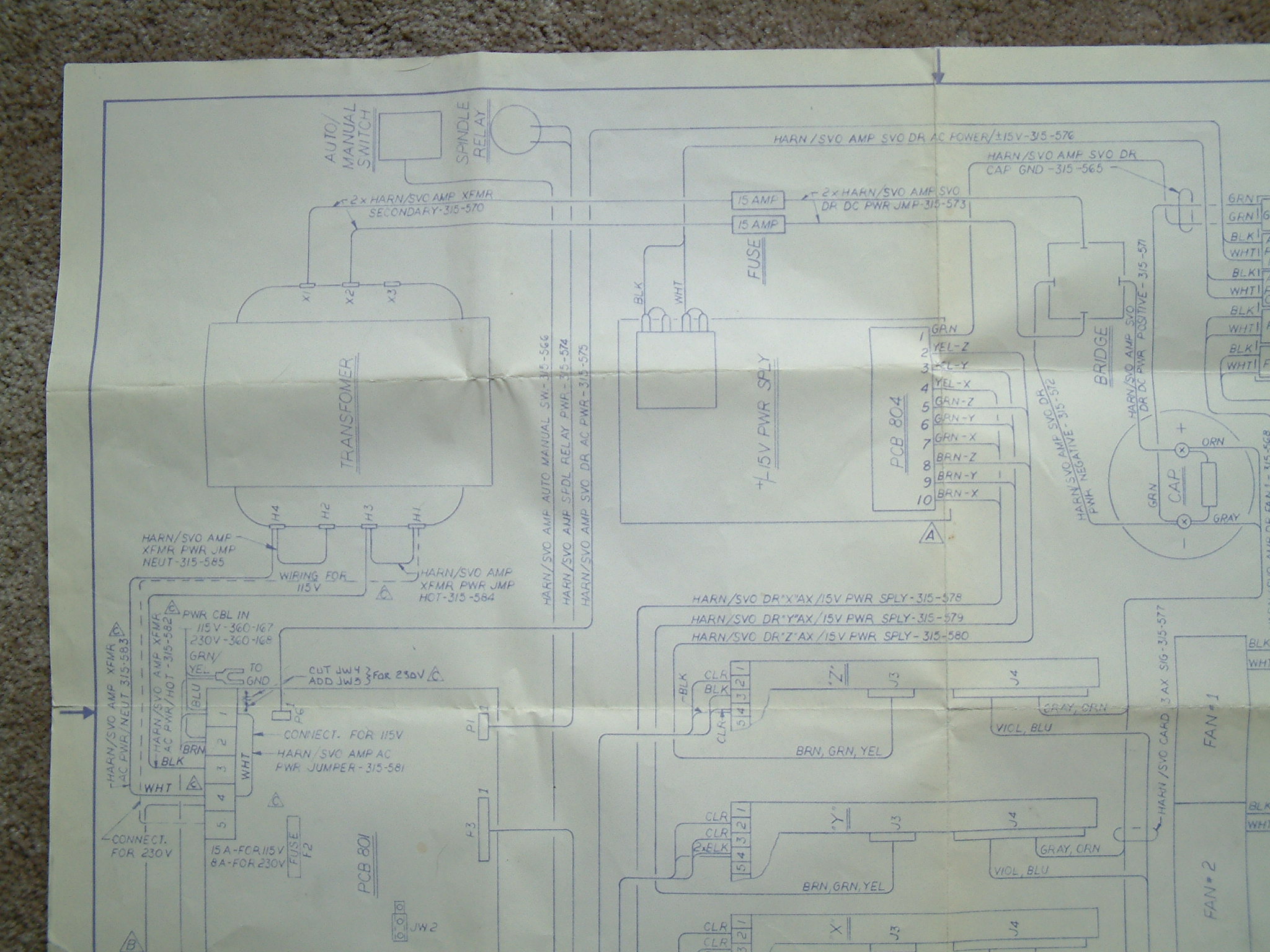
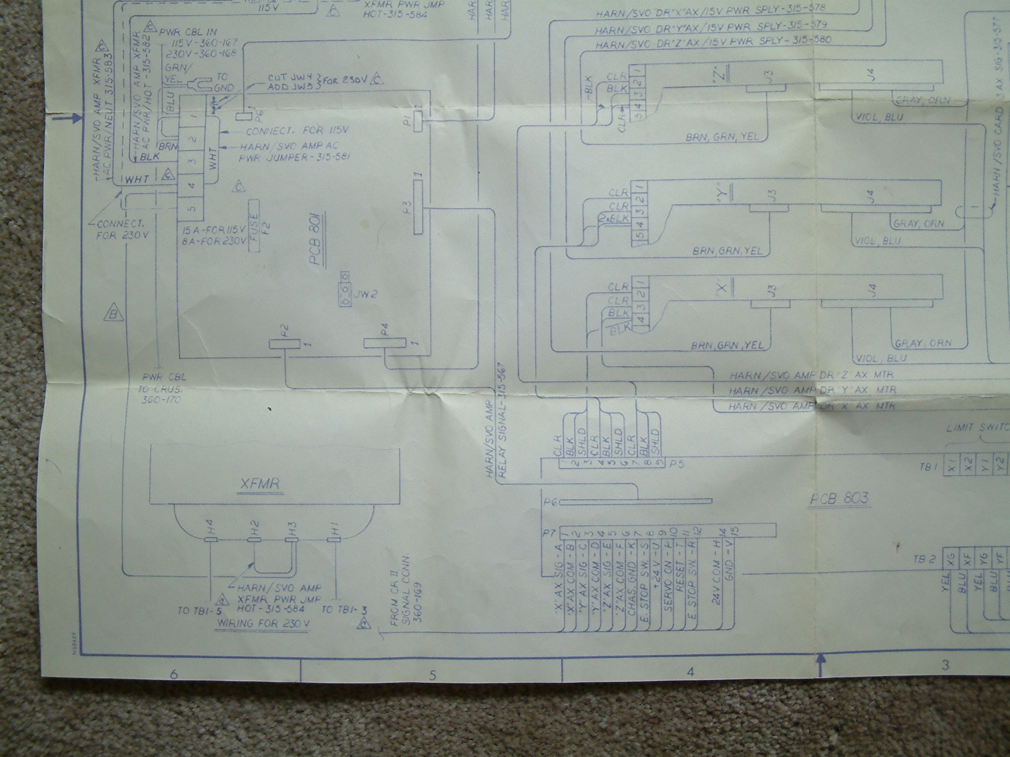
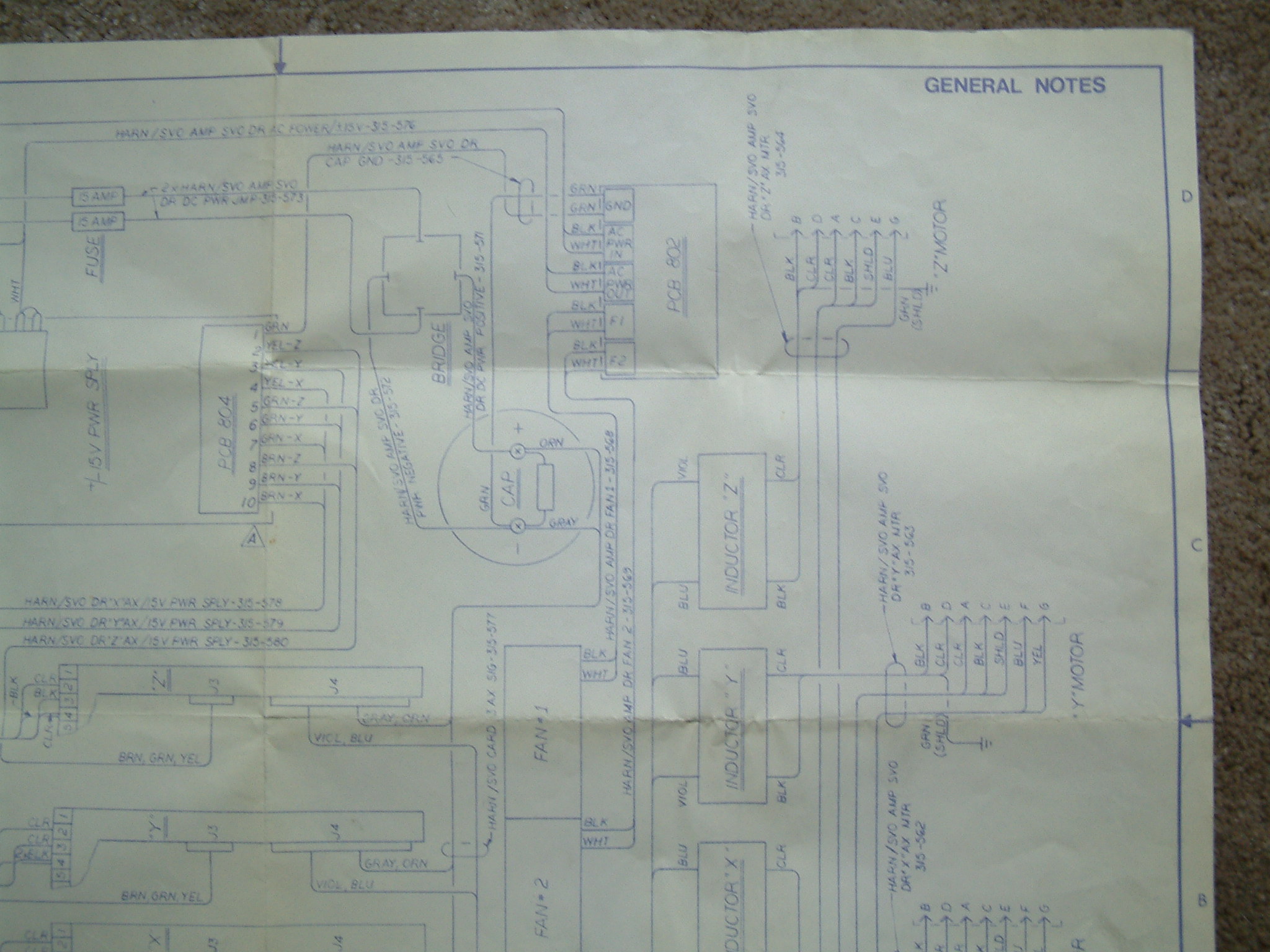
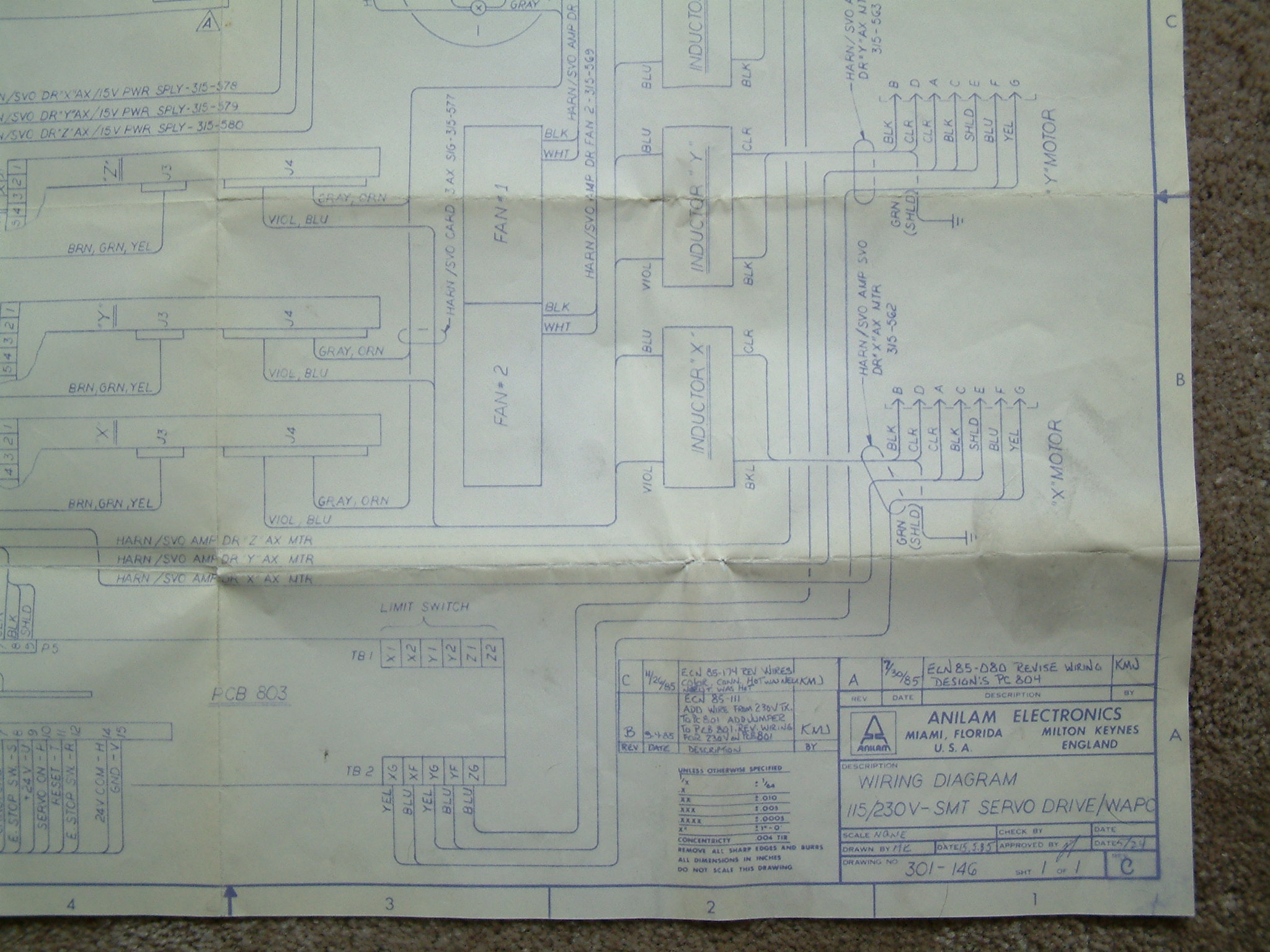
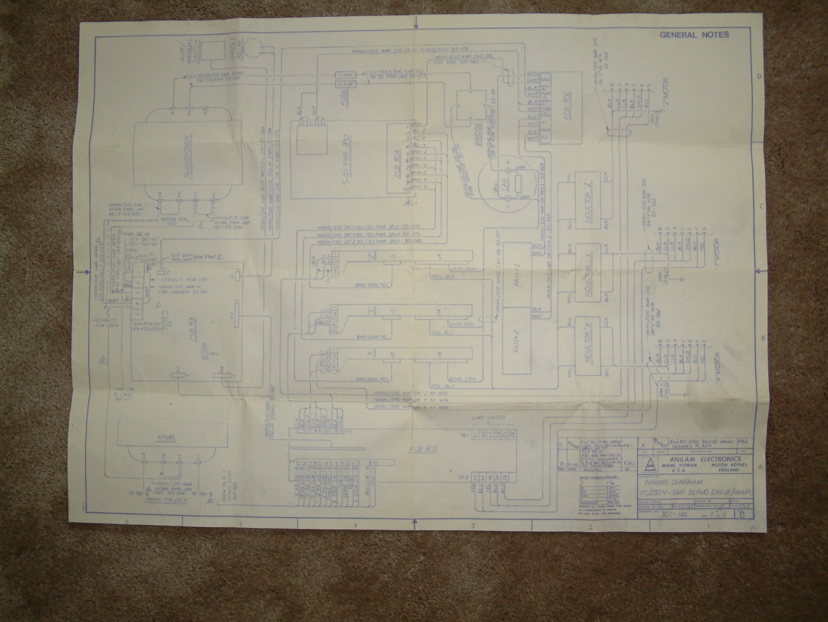
On your sketch, upper circuit, I believe that the contactor may already exist on the on the PCB 801. You can see it below in the attached photo #0002.jpg. photo 5 is the whole schematic and the others are closer shots of each corner.
Jim
Yes after looking at the ebay item closer it appears to be for a automotive application and trying to power it with the output from the ATA power supply it may not get whatever is required for this circuit.
As far as the limit switches voltage requirements they should do fine 24 volts as the Z axis uses ones like THIS and the X & Y use plunger types like THESE .
On your sketch, upper circuit, I believe that the contactor may already exist on the on the PCB 801. You can see it below in the attached photo #0002.jpg. photo 5 is the whole schematic and the others are closer shots of each corner.
Jim
Please Log in or Create an account to join the conversation.
- FloppyDisk
-
- Offline
- New Member
-
Less
More
- Posts: 18
- Thank you received: 3
19 Mar 2016 21:53 #71912
by FloppyDisk
Replied by FloppyDisk on topic Crusader II retrofit
Hi Jamby,
Those TEMCo Cross Roller Plunger Limit Switches should work fine at 24vdc.
As far as the contactor on your board, you're now at a point where you need to make a decision on what you want to do. Your schematics look similar to my Anilam Crusader M and I had a board w/ 3 relays on it, but the problem was that the Anilam circuit board was powered 'backwards' for the outputs from the 7i77, ie the 7i77 output sources 24vdc and the Anilam circuit board was setup to sink 24vdc. For me, I simply didn't use two of the relays and wired one 'backwards' so that I could use the sourcing 24vdc output from the 7i77. If that makes sense... I wired in the relay to turn-on the servo amplifiers and left the others disconnected. For my estop, I wired in a safety relay and contactor, but the latching circuit I drew would work fine as well.
Mark
Please Log in or Create an account to join the conversation.
- jamby
- Offline
- Elite Member
-
Less
More
- Posts: 235
- Thank you received: 6
19 Mar 2016 22:11 #71913
by jamby
Replied by jamby on topic Crusader II retrofit
Mark
I believe the 801 board has (2) relays on it.
Your M controller was the next version after my crusader II controller.
Looks like I need to learn how to chase down how my circuit works.
Thanks for you help
Jim
I believe the 801 board has (2) relays on it.
Your M controller was the next version after my crusader II controller.
Looks like I need to learn how to chase down how my circuit works.
Thanks for you help
Jim
Please Log in or Create an account to join the conversation.
- FloppyDisk
-
- Offline
- New Member
-
Less
More
- Posts: 18
- Thank you received: 3
19 Mar 2016 22:18 #71914
by FloppyDisk
Replied by FloppyDisk on topic Crusader II retrofit
Somehow, I had a schematic for my board w/ 3 relays on it. If I were to do it again, I might consider ripping out the anilam circuit board and use stand-alone ice cube relays something like this: www.ebay.com/itm/381573347562. On the Crusader M, they used those type of relays on the circuit board and then went to a larger SSR to turn on/off the servo amplifiers.
Please Log in or Create an account to join the conversation.
- jamby
- Offline
- Elite Member
-
Less
More
- Posts: 235
- Thank you received: 6
01 Apr 2016 21:13 #72531
by jamby
Replied by jamby on topic Crusader II retrofit
Well I have been making parts with my current setup, that is using the Anilam "Red" card to handle E-stop and Limits and having Linuxcnc control the drives. But the one problem that concerns me is Linuxcnc doesn't know when the E-stop or Limit is tripped and with the Limits when power is restored the axis will jump, unless I hit e-stop or power off on Linuxcnc.
There is a 15v power connection on the amplifier boards that I could connect to the Mesa 7i77 and then write a hal handler to power off Linuxcnc when that voltage drops to "0".
Does this sound like it would work?
with +15v coming from the 15volt 1.5 amp power-one card.
Thanks
Jim
There is a 15v power connection on the amplifier boards that I could connect to the Mesa 7i77 and then write a hal handler to power off Linuxcnc when that voltage drops to "0".
Does this sound like it would work?
with +15v coming from the 15volt 1.5 amp power-one card.
Thanks
Jim
Please Log in or Create an account to join the conversation.
Time to create page: 0.767 seconds