1 or 2 dedicated 120VAC circuits for my CNC?
- Sray69
- Offline
- Elite Member
-

- Posts: 255
- Thank you received: 13
If so, I could really use a little detail on how to install it. You mentioned
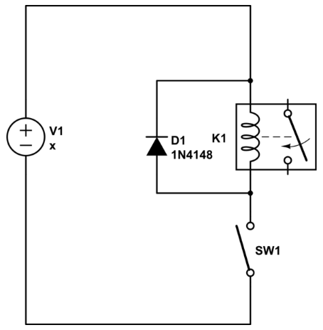
Based on the diagrams I found of flyback diodes the they are soldered in between the positive/negative side of the relay winding like this image.wired in parallel to relay winding, just mind the polarity in regard to Mesa output.
I would use another smaller relay in between, or a transistor.
So I would install the diode between the DC pos/neg input on the contactor? Which side would the stripe face? I have read it both ways (toward the neg/toward the pos).
Attachments:
Please Log in or Create an account to join the conversation.
- spumco
- Offline
- Platinum Member
-

- Posts: 2126
- Thank you received: 882
I don't remember if you're triggering the contactor coil directly from your Mesa board or if you've got an intermediate device (relay). Whichever it is, compare the contactor coil (or intermediate relay coil) amp draw against the Mesa output specs to make sure you aren't drawing too much.
I should have mentioned this way back in our discussions of your wiring, but I didn't realize how much of a problem this is until I got caught out myself a couple months ago. In my case, I had flyback diodes on relays controlling some air solenoid valves. Turns out the coils on the solenoid valves ALSO needed diodes as they were powered by the same circuit as the relay coils. Tearing my hair out until PCW cam along and pointed out the error of my ways.
forum.linuxcnc.org/27-driver-boards/4803...rrent-overtemp-error
Please Log in or Create an account to join the conversation.
- Sray69
- Offline
- Elite Member
-
- Posts: 255
- Thank you received: 13
The image is just an example. Instead of a solenoid valve I have a contactor. Am I correct in thinking that I can install my diode in the same orientation (stripe towards the + side)?
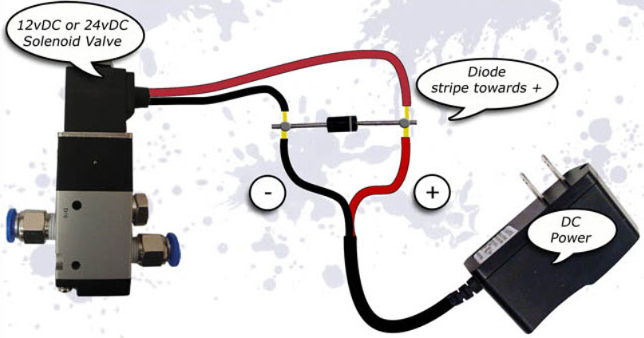
Here is a somewhat helpful explanation I found of what the stripe means and how to orient it. Provided this is correct information.
Can someone let me know if my thinking is correct?Think of the stripe as an arrow showing you which way current is allowed to flow through it, and imagine you just unplugged the power supply. Understanding that current will no longer go through the power supply, you should be able to see that it will now flow out of the coil and through the diode.If that diode were not installed, the coil can produce something called inductive kick, which can and will destroy the power supply by pushing voltage higher until it gets current flow - possibly through something that shouldn't be passing current.
Attachments:
Please Log in or Create an account to join the conversation.
- Sray69
- Offline
- Elite Member
-
- Posts: 255
- Thank you received: 13
Here are the DC specs of the contactor. I assume that the AC specs don't apply since the Mesa only provides the DC signal?
Rated Control Circuit Voltage (Uc):
- Operation 24 V
- Average Holding Value, from Warm State 2 W
- Average Pull-in Value, from Cold State 90 W
- Pull-in at Max. Rated Control Circuit Voltage DC 90 W
Not sure if this is what is needed. Or if it is too high.
Here is the Specification page: new.abb.com/products/1SBL189001R8100/ae16-30-00-24v-dc
Thanks for jumping in.
Please Log in or Create an account to join the conversation.
- Sray69
- Offline
- Elite Member
-
- Posts: 255
- Thank you received: 13
DC rated voltage (VDC): 600
DC thermal rated current (A): 5
DC Maximum make-break (A): 0.2
Are any of these helpful in determining the amp draw?
Here is the Output info for the Mesa. Having a hard time determining what exactly I am comparing.
FIELD I/O
The 7I76E has a 32 input, 16 output isolated field I/O system to support a wide range of input and output devices. The isolated I/O is intended for low voltage DC control systems (commonly 24VDC). Inputs are sinking type. That is they sense positive input voltages relative to field ground. Outputs are sourcing (7I76E) or sinking (7I76ED) type. Sourcing outputs supply field power to field ground referred loads. Sinking outputs ground field voltage referred loads when on.
VIN AND FIELD POWER SUPPLY
The 7I76E field I/O runs from field power supplies of 5 to 32 VDC. Field power supplies the power to the 7I76E outputs and determines the 7I76E input thresholds. VIN power runs the field I/O processor and normally is connected to field power. VIN must be greater than 8V for proper operation. This means VIN must come from a separate source if 5V field voltage is used. Power consumption is approximately 600 mW or 25 mA at 24V. VIN power must be present for the 7I76E field I/O to be detected and operate. Field voltages that are too high or too low will cause faults. Field power must have a ramp up rate of less than 10V/Millisecond. This means that you cannot switch the field power connection with a switch or relay.
FIELD OUTPUT CHARACTERISTICS
The 7I76E (no D) field outputs are high side or sourcing type drivers, that is they source positive voltage to a ground referred load. For example with a standard 24V field power, +24V connects to the 7I76Es field power input (on TB1) and the outputs on TB5 and TB6 now source +24V power to loads. All 7I76 loads will have one side returned to ground or the negative lead of the 24V supply. The 7I76s outputs can drive loads of up to 350 mA. The 7I76ED field outputs are low side or sinking type drivers, that is they ground the load side of a field voltage referred load.
SOURCING VS SINKING OUTPUTS
The advantage of sourcing type field wiring is that it is less likely to cause inadvertent device actuation from the most likely type of field wiring problem which is a short to ground. The advantage of sinking drivers is compatibility with existing hardware on retrofits and the capability of using mixed output voltages.
SHORT CIRCUIT PROTECTION
The 7I76Es outputs have short circuit protection and will turn off if short circuit current exceeds approximately 800 mA. The 7I76E firmware will detect this condition, disable the affected output and indicate a fault.
OVERTEMPERATURE PROTECTION
The output driver chips detect over temperature conditions. If the 7I76E detects a driver chip with a over temperature warning flag asserted, it will disable the affected chip and indicate a fault.
MAXIMUM PER CHIP CURRENT
Because of thermal limitations there is a maximum per driver chip total current of 1.4 amps continuous. Each driver chip connects to 8 sequential outputs. If this limit is exceeded, the driver chip may go into thermal shutdown.
VOLTAGE CLAMPS
The output driver chips used on the 7I76E have built in Zener diode clamps to clamp inductive turn-off (fly-back) spikes. This means that flyback diodes are not normally required on small (less than 60 mA) inductive loads. If high current inductive loads are switched or inductive loads are switched at high frequencies, they must have flyback diodes to limit power dissipation in the 7I76E's driver chips.
Please Log in or Create an account to join the conversation.
- tommylight
-

- Offline
- Moderator
-

- Posts: 21700
- Thank you received: 7417
If the info is correct, the relay pulls nearly 4A @24V when powered on and needs only under 0.1A to hold.
Add another small relay with 5A contacts.
Please Log in or Create an account to join the conversation.
- spumco
- Offline
- Platinum Member
-
- Posts: 2126
- Thank you received: 882
Having a hard time determining what exactly I am comparing.
MAXIMUM PER CHIP CURRENT
Because of thermal limitations there is a maximum per driver chip total current of 1.4 amps continuous. Each driver chip connects to 8 sequential outputs. If this limit is exceeded, the driver chip may go into thermal shutdown.
Each output is shared with 7 others on a single driver chip. Each driver chip can handle 1.4a total. So you can have one output sinking 1.39A, but if another output turns on the chip will go in to thermal shutown. If you're using all 8 at the same time you get 1.4/8a (0.175a).
Tommy's right (as usual) - you need another relay between the contactor and the Mesa output. The additional relay should have a built-in flyback diode just to be safe.
When I had to re-do some of my stuff - mentioned earlier - I switched from the mechanical relays I'd been using to solid-state transitor relays. Not the big boxy SSR's for high-amp use, but small DIN-rail optocouplers used for low-amp switching.
Here's a Murr Elektronic optocoupler rated for 10A and operates at 24vdc:
www.ebay.com/itm/321398959389
But if you've already got a small 5A relay that'll fit in the cabinet you can add a diode to the coil and switch the contactor with that.
Please Log in or Create an account to join the conversation.
- Sray69
- Offline
- Elite Member
-
- Posts: 255
- Thank you received: 13
I may have an extra Omron 10amp relay left over. Will have to look through my stuff. If not I will try a SSR.
Please Log in or Create an account to join the conversation.
- Sray69
- Offline
- Elite Member
-
- Posts: 255
- Thank you received: 13
Unfortunately I cannot get it to work. Maybe I am hooking it up incorrectly. I am not sure. The way I had the circuit setup originally was that I had the 24V signal coming from the output pin 01 (Mesa) to the A1 terminal and the A2 terminal (on the contactor) going to DC ground in the cabinet.
All I did was install the SSR inline with neg-neg and pos-pos with a diode on the input side (with stripe toward the positive side). See image.
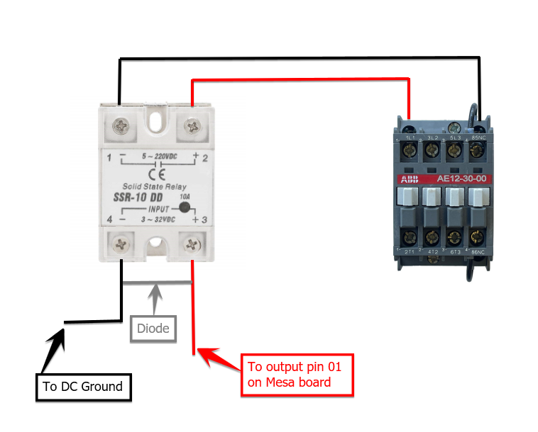
Is this the correct way to connect it?
NOTE: I do not show the high voltage connections on the contactor.
When I enable the circuit I get a red light on the SSR. When I test the voltage I am getting 24V on the input side and zero volts on the output side.
Attachments:
Please Log in or Create an account to join the conversation.
- spumco
- Offline
- Platinum Member
-
- Posts: 2126
- Thank you received: 882
2. What is powering the load side of the SSR? remember - it's a switch. It does't pass voltage through from the control side to the load side.
The load side (contactor side) needs a power supply. Assuming your contactor coil is 24vdc, your circuit should be:
+24vdc -> SSR+(2) (power supply V+ to SSR+)
SSR-(1) -> contactor A1 (SSR- to contactor coil V+)
contactor A2 -> 0VDC (contactor coil to power supply V-)
3. Assuming you're powering the contactor coil from the same PSU as that which is powering the Mesa... put the diode across the contactor coil and not the SSR. The SSR turning off doesn't create a reverse voltage spike, but the contactor coil will - and that may work it's way back to the Mesa without a flyback diode. Connect the diode acrosss contactor A1 & A2, with the stripe to the A1 side.
Please Log in or Create an account to join the conversation.