1 or 2 dedicated 120VAC circuits for my CNC?
- Sray69
- Offline
- Elite Member
-

Less
More
- Posts: 255
- Thank you received: 13
19 Nov 2022 04:39 #257092
by Sray69
Replied by Sray69 on topic 1 or 2 dedicated 120VAC circuits for my CNC?
Question about the IoT Power Relay. Since the IoT Relay has a relay built in (2xNO, 1xNC), would I still need another relay in my cabinet in order to trigger the IoT relay? It is my understanding that the IoT relay can take an input voltage of 3.3V-48V. Couldn't I just run a Digital Out (24V) to the + side of the IoT relay and then pull from the negative of the PSU for the - side of the IoT relay? Then in LCNC assign the Digital Out to trigger when the E-stop circuit (Digital In) is activated?
Please Log in or Create an account to join the conversation.
- spumco
- Offline
- Platinum Member
-

Less
More
- Posts: 2107
- Thank you received: 874
19 Nov 2022 14:24 - 19 Nov 2022 14:26 #257108
by spumco
Replied by spumco on topic 1 or 2 dedicated 120VAC circuits for my CNC?
You can still pull this off with 120vac.
There are 30A "RV" receptacles available for 120vac circuits. They're used to connect RV's to shore power at campsites.
If you add a 30A breaker and a dedicated 30A receptacle to your box you should be able to power everything (including the router) from a single cord.
Most hardware stores and Scamazon have these 30A receptacles & matching plugs available. According to the NEC ampacity chart, you'll need 10AWG conductors if you use portable power cord rated for 90c.
Easiest thing to do would be buy the 30A breaker, receptacle, an "RV" plug that matches the receptacle, and 10' or so of 2-conductor (plus ground) SJOOW cord.
EDIT - remember you'll need 10AWG from the breaker to the receptacle, too. This stuff gets expensive when you need big amps.
Last edit: 19 Nov 2022 14:26 by spumco.
Please Log in or Create an account to join the conversation.
- Sray69
- Offline
- Elite Member
-
Less
More
- Posts: 255
- Thank you received: 13
19 Nov 2022 16:06 #257114
by Sray69
Replied by Sray69 on topic 1 or 2 dedicated 120VAC circuits for my CNC?
I like that idea but unfortunately I already ordered my 20A breakers for my panel. I will have to see how much of a hassle it would be to return.
I added the IoT Power Relay (to shut off router when E-stop is pressed) to my E-stop circuit drawing. Because it has a built in relay, I am wondering if this is how I would add it to my system? My thought is I could trigger terminal "do 01" ON when the E-stop button is pressed just like terminal "do 00". Would this work?
drive.google.com/file/d/1MT1tXdgEZn4DbXC...Dn3/view?usp=sharing
Thanks
Please Log in or Create an account to join the conversation.
- spumco
- Offline
- Platinum Member
-
Less
More
- Posts: 2107
- Thank you received: 874
19 Nov 2022 16:20 - 19 Nov 2022 18:24 #257115
by spumco
Replied by spumco on topic 1 or 2 dedicated 120VAC circuits for my CNC?
Give me a minute, I'm cooking up a diagram for you that has everything you need...
EDIT...
Diagram attached. Has a two button on/off function to energize the system and keep it from turning back on in the event of a power loss.
Also allows LCNC to control the spindle on/off, but both the drive power supply and spindle will be de-energized if you press the estop.
None of the user buttons have more than 24VDC going through them.
Let me know if you need further explanation. Breakers/fuse ratings are up to you.
BTW, I'm not a fan of SSR's for safety or critical stuff as they tend to fail closed (i.e. energized) and don't break the circuit.
Last edit: 19 Nov 2022 18:24 by spumco.
The following user(s) said Thank You: Sray69
Please Log in or Create an account to join the conversation.
- Sray69
- Offline
- Elite Member
-
Less
More
- Posts: 255
- Thank you received: 13
19 Nov 2022 20:10 #257120
by Sray69
Replied by Sray69 on topic 1 or 2 dedicated 120VAC circuits for my CNC?
I have a question about the E-stop. It says it has 2 NC contacts. It is my understanding that both contacts would be closed/energized when the button is up.
First NC:
By looking the diagram it looks like one NC is supplying the ground to the 24VDC Coil SSR. Meaning that when the button is up the negative is provided to the Coil SSR (closing the 120VAC relay) which in turn keeps the 120V receptacle powered. When the button is pushed, the negative is then disconnected, opening the relay which shuts the power off to the receptacle.
Second NC:
With this circuit energized when the button is up, does this mean that in HAL I would need to invert the state to "NOT" in order to make this setup work?
Am I understanding this correctly?
Please Log in or Create an account to join the conversation.
- spumco
- Offline
- Platinum Member
-
Less
More
- Posts: 2107
- Thank you received: 874
19 Nov 2022 20:47 #257122
by spumco
Correct on both questions.
If you want a 'belt and suspenders' arrangement, then supply the 120VAC SSR 120V-in to the contactor's 120VAC output instead of directly from the 120VAC terminal blocks. In this arrangement even if the SSR fails closed (passing current) the estop button will open the contactor's coil and all 120VAC to the drive PSU and reouter SSR will be stopped.
I've attached a REV1 version if my explanation wasn't clear.
Basically, the contactor can kill power to all motion components but does not kill power to Mesa, LCNC, or sensors/instruments/etc. The contactor will need to be rated appropriately, of course.
Further options are possible... such as indicator lights showing status (on, off, estop active, etc.) but I simplified a bit. You can add fuses to the 24vdc circuit(s) if you'd like. Just don't put a switch or relay between the 24VSC PSU and the Mesa V+ terminals.
If you have a 7i76ED (sinking outputs) version, the diagram will need some modification.
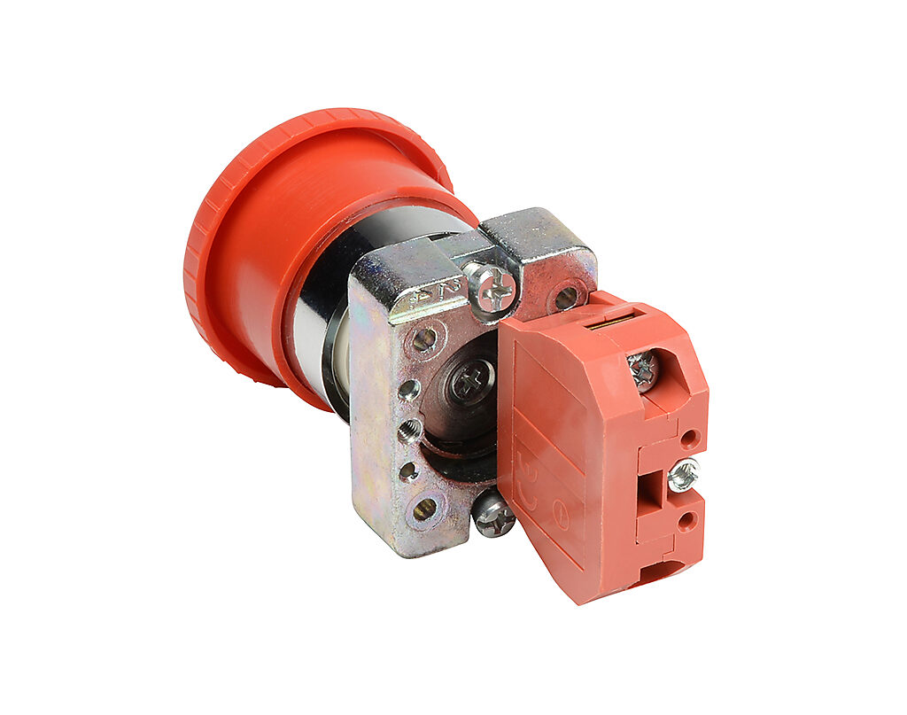
The estop switch should be one of the 'industrial' types where you can either stack separate contacts, or use two NC contact blocks for a single button.
Like this:
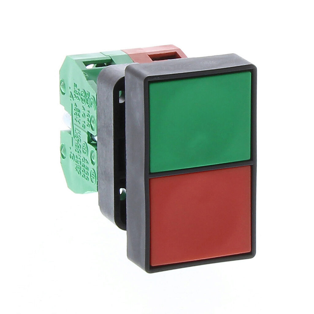
And the ON/OFF buttons can be a single switch as well. Here's an example:
Replied by spumco on topic 1 or 2 dedicated 120VAC circuits for my CNC?
I have a question about the E-stop. It says it has 2 NC contacts. It is my understanding that both contacts would be closed/energized when the button is up.
First NC:
By looking the diagram it looks like one NC is supplying the ground to the 24VDC Coil SSR. Meaning that when the button is up the negative is provided to the Coil SSR (closing the 120VAC relay) which in turn keeps the 120V receptacle powered. When the button is pushed, the negative is then disconnected, opening the relay which shuts the power off to the receptacle.
Second NC:
With this circuit energized when the button is up, does this mean that in HAL I would need to invert the state to "NOT" in order to make this setup work?
Am I understanding this correctly?
Correct on both questions.
- LCNC supplies 24vdc to router SSR via Mesa 7i76e when 'spindle on' is commanded.
- If the estop button is out (contacts closed), spindle can turn on.
- If the estop button is asserted, the SSR stays open even if LCNC is commanding "spindle on" for some odd reason.
- The second set of contacts is used to signal 'external estop' to LCNC through the Mesa input.
- You will need to use the inverted input (7i76e.something.input-NN-not) for the external estop signal. Using an NC circuit like this means LCNC will receive the estop-is-asserted signal if the button is pushed AND if there is a broken wire or loose conection. i.e. a fail-safe arrangement.
If you want a 'belt and suspenders' arrangement, then supply the 120VAC SSR 120V-in to the contactor's 120VAC output instead of directly from the 120VAC terminal blocks. In this arrangement even if the SSR fails closed (passing current) the estop button will open the contactor's coil and all 120VAC to the drive PSU and reouter SSR will be stopped.
I've attached a REV1 version if my explanation wasn't clear.
Basically, the contactor can kill power to all motion components but does not kill power to Mesa, LCNC, or sensors/instruments/etc. The contactor will need to be rated appropriately, of course.
Further options are possible... such as indicator lights showing status (on, off, estop active, etc.) but I simplified a bit. You can add fuses to the 24vdc circuit(s) if you'd like. Just don't put a switch or relay between the 24VSC PSU and the Mesa V+ terminals.
If you have a 7i76ED (sinking outputs) version, the diagram will need some modification.
The estop switch should be one of the 'industrial' types where you can either stack separate contacts, or use two NC contact blocks for a single button.
Like this:
And the ON/OFF buttons can be a single switch as well. Here's an example:
The following user(s) said Thank You: arvidb
Please Log in or Create an account to join the conversation.
- Sray69
- Offline
- Elite Member
-
Less
More
- Posts: 255
- Thank you received: 13
19 Nov 2022 21:54 #257125
by Sray69
Replied by Sray69 on topic 1 or 2 dedicated 120VAC circuits for my CNC?
Well this is giving me a lot to think about. I really like the diagrams you provided. VERY helpful!
I do like the idea of not having to run 120VAC power to my E-stops. I also like the idea of running one cord to the cabinet and having a switched 120VAC receptacle to power the router from the cabinet.
But as I mentioned I already purchased my 20A breakers online and I have already sourced all the hardware, wire and components (except for the IoT Power Relay (still unsure on how this is connected)) for my system based on this diagram. My diagram is very basic compared to yours. More of a visual aid so it is easy for me to understand as I assemble the cabinet. The light gray square represents the cabinet. It is not to scale by any means but it is a rough representation of the layout I plan to use.
drive.google.com/file/d/1XuMKF-9na09gS-y...5pM/view?usp=sharing
I will have to spend some time going over the diagrams and determine if I can apply some parts of your diagrams to mine.
Thanks so much for the help.
Please Log in or Create an account to join the conversation.
- spumco
- Offline
- Platinum Member
-
Less
More
- Posts: 2107
- Thank you received: 874
20 Nov 2022 02:06 #257139
by spumco
Replied by spumco on topic 1 or 2 dedicated 120VAC circuits for my CNC?
The "IOT" relay you pictured - assuming the dingus I found on Amazon that looks identical is the same thing - is a 30A relay connected to 4x receptacles. It has an on-board 5vdc PSU and an optocoupler so an arduino or other 3.3v microcontroller can trigger it. Or it can be triggered by a 120VAC input.
It's about as "Internet of Things" as my chainsaw.
You can accomplish the same thing with just a relay and a second power cord from the wall. The IOT thing is $30, and a plain old 30A relay with an opto built-in is $8. Or you could get a good quality DIN-rail ice cube relay & holder from Automation Direct for about $15.
The main disconnect switch you have pictured is one of those cheapo computer C13 things with a built-in switch. I've gone through 2 or 3 of them - the switch dies. I suggest you get a real disconnect switch rated for your max current. Should look like this:
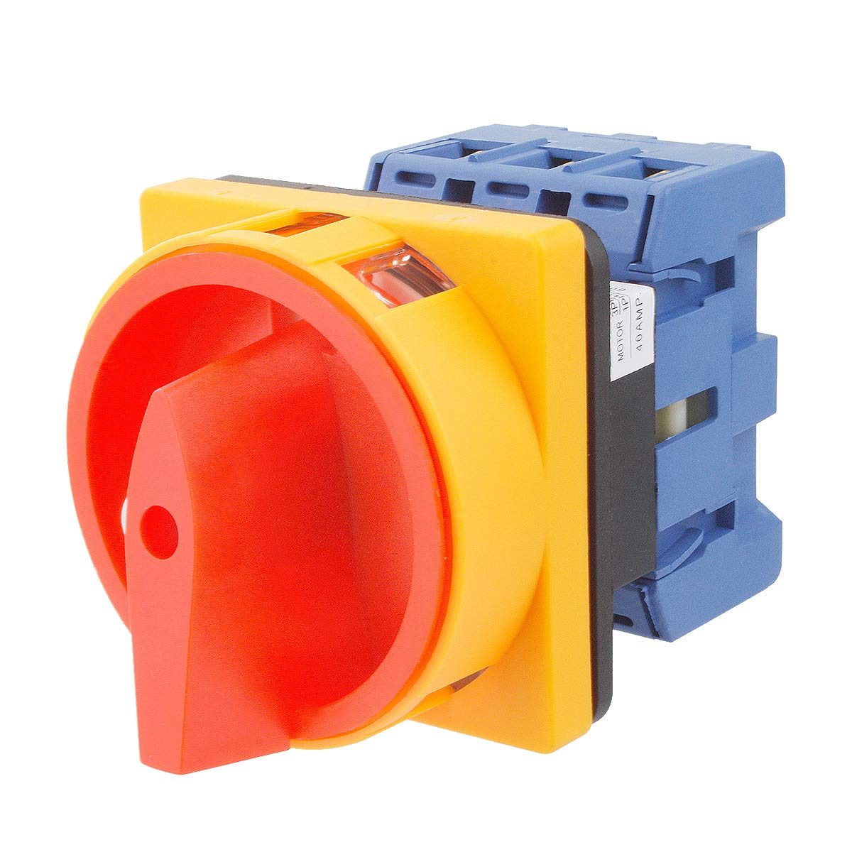
Tha't a 40A 3-pole disconnect for $18.
Regarding the breakers... they aren't wasted money. If you buy a 30A breaker you now have spare breakers for your box - always a good move for any homeowner.
The thing is, we're getting in to 'philosophy' and opinions now about how to design & wire up a CNC machine. As you've probably discovered already, everyone has their own opinions about what to do. You can do it cheap, you can do it sort-of cheap and pretty safe, and you can spend $$$ and make it really robust & super-safe. My personal philosophy on control systems:
It's about as "Internet of Things" as my chainsaw.
You can accomplish the same thing with just a relay and a second power cord from the wall. The IOT thing is $30, and a plain old 30A relay with an opto built-in is $8. Or you could get a good quality DIN-rail ice cube relay & holder from Automation Direct for about $15.
The main disconnect switch you have pictured is one of those cheapo computer C13 things with a built-in switch. I've gone through 2 or 3 of them - the switch dies. I suggest you get a real disconnect switch rated for your max current. Should look like this:
Tha't a 40A 3-pole disconnect for $18.
Regarding the breakers... they aren't wasted money. If you buy a 30A breaker you now have spare breakers for your box - always a good move for any homeowner.
The thing is, we're getting in to 'philosophy' and opinions now about how to design & wire up a CNC machine. As you've probably discovered already, everyone has their own opinions about what to do. You can do it cheap, you can do it sort-of cheap and pretty safe, and you can spend $$$ and make it really robust & super-safe. My personal philosophy on control systems:
- Use decent quality components, no garbage, no-name junk unless the only alternative is hyper-expensive and there's no safety consequence. For personal equipment, no need for Allen-Bradley, AB, or Siemens priced stuff... but not AliExpress stuff if a failure means a safety issue or fire.
- The human should always be able to stop motion and meat-carving components without relying on software and (software-controlled hardware).
- A hard estop (not software "estop") should be able to be asserted by both human and software, but only human can recover from the estop.
- Everything fails, eventually. If it takes more than 10 minutes on the internet to find a datasheet and identical replacement of what you're thinking of buying, buy something else.
- Buy high-quality wire, rated for 105c minimum. The insulation is usually thinner - makes it easier to wire up a panel.
- Splurge on decent wiring tools, including wire labeling equipment. Heat-shirink tube printers are magical.
- Whatever your budget, double it.
Attachments:
The following user(s) said Thank You: Sray69
Please Log in or Create an account to join the conversation.
- Sray69
- Offline
- Elite Member
-
Less
More
- Posts: 255
- Thank you received: 13
20 Nov 2022 04:59 #257141
by Sray69
I guess I have some things to figure out. I will have to determine what components I can keep and what I can return. Amazon is going to cut me off here pretty soon. LOL. I have been returning a ton of shit lately. I am hoping that since I end up spending more than I return to replace items they shouldn't have much to complain about.
Your diagram reminds me of this guys post/video of his safety circuit setup. I was planning to go this route but was told by others that I don't need to use a contactor with a 120VAC setup and that I just need to use a SSR. Since I reached out to the guy for some details on his setup and never heard back I decided I would move on and take advice from those that were helping me since I am not well versed in electronics. I like the guys setup with the illuminated E-stop and the momentary buttons and how he did a video showing how they all work together. He also lists the components he used. They are similar to the E-stop you posted in the fact can purchase separate NC/NO contact blocks that can be used with many of their stops/switches/buttons.
www.peterverdone.com/cnc-control-box-power-safety-circuit/
Here are all the Alpinetech stops/switches/buttons on Amazon
smile.amazon.com/s?k=Alpinetech&qid=1668919326&ref=sr_pg_1
Would these be worth purchasing?
Also if I go with a 30A breaker would this disconnect (32A version) suffice?
smile.amazon.com/Rotary-Changeover-2-Pos...8917297&sr=8-39&th=1
I will work more on this in the morning and let you know what I come with as well as any further questions I may have.
Thanks
Replied by Sray69 on topic 1 or 2 dedicated 120VAC circuits for my CNC?
As far as my budget, I am long past doubling it. I want to do it right but I also don't feel I need to pay through the nose for everything as you stated.The "IOT" relay you pictured - assuming the dingus I found on Amazon that looks identical is the same thing - is a 30A relay connected to 4x receptacles. It has an on-board 5vdc PSU and an optocoupler so an arduino or other 3.3v microcontroller can trigger it. Or it can be triggered by a 120VAC input.
It's about as "Internet of Things" as my chainsaw.
You can accomplish the same thing with just a relay and a second power cord from the wall. The IOT thing is $30, and a plain old 30A relay with an opto built-in is $8. Or you could get a good quality DIN-rail ice cube relay & holder from Automation Direct for about $15.
The main disconnect switch you have pictured is one of those cheapo computer C13 things with a built-in switch. I've gone through 2 or 3 of them - the switch dies. I suggest you get a real disconnect switch rated for your max current. Should look like this:
Tha't a 40A 3-pole disconnect for $18.
Regarding the breakers... they aren't wasted money. If you buy a 30A breaker you now have spare breakers for your box - always a good move for any homeowner.
The thing is, we're getting in to 'philosophy' and opinions now about how to design & wire up a CNC machine. As you've probably discovered already, everyone has their own opinions about what to do. You can do it cheap, you can do it sort-of cheap and pretty safe, and you can spend $$$ and make it really robust & super-safe. My personal philosophy on control systems:
- Use decent quality components, no garbage, no-name junk unless the only alternative is hyper-expensive and there's no safety consequence. For personal equipment, no need for Allen-Bradley, AB, or Siemens priced stuff... but not AliExpress stuff if a failure means a safety issue or fire.
- The human should always be able to stop motion and meat-carving components without relying on software and (software-controlled hardware).
- A hard estop (not software "estop") should be able to be asserted by both human and software, but only human can recover from the estop.
- Everything fails, eventually. If it takes more than 10 minutes on the internet to find a datasheet and identical replacement of what you're thinking of buying, buy something else.
- Buy high-quality wire, rated for 105c minimum. The insulation is usually thinner - makes it easier to wire up a panel.
- Splurge on decent wiring tools, including wire labeling equipment. Heat-shirink tube printers are magical.
- Whatever your budget, double it.
I guess I have some things to figure out. I will have to determine what components I can keep and what I can return. Amazon is going to cut me off here pretty soon. LOL. I have been returning a ton of shit lately. I am hoping that since I end up spending more than I return to replace items they shouldn't have much to complain about.
Your diagram reminds me of this guys post/video of his safety circuit setup. I was planning to go this route but was told by others that I don't need to use a contactor with a 120VAC setup and that I just need to use a SSR. Since I reached out to the guy for some details on his setup and never heard back I decided I would move on and take advice from those that were helping me since I am not well versed in electronics. I like the guys setup with the illuminated E-stop and the momentary buttons and how he did a video showing how they all work together. He also lists the components he used. They are similar to the E-stop you posted in the fact can purchase separate NC/NO contact blocks that can be used with many of their stops/switches/buttons.
www.peterverdone.com/cnc-control-box-power-safety-circuit/
Here are all the Alpinetech stops/switches/buttons on Amazon
smile.amazon.com/s?k=Alpinetech&qid=1668919326&ref=sr_pg_1
Would these be worth purchasing?
Also if I go with a 30A breaker would this disconnect (32A version) suffice?
smile.amazon.com/Rotary-Changeover-2-Pos...8917297&sr=8-39&th=1
I will work more on this in the morning and let you know what I come with as well as any further questions I may have.
Thanks
Please Log in or Create an account to join the conversation.
- spumco
- Offline
- Platinum Member
-
Less
More
- Posts: 2107
- Thank you received: 874
20 Nov 2022 06:00 #257143
by spumco
Replied by spumco on topic 1 or 2 dedicated 120VAC circuits for my CNC?
Trust me, I get it... this whole hobby is a series of tech rabbit holes. And you will wind up with a pile of parts you don't know what to do with.
Disconnect switch - yes, that'd be far superior to the little rocker switch you originally had.
Alpintech switches are OK, but they're pricey on Amazon and they use contacts & operators (the actual button part of the assembly) that don't interchange with other brands. For the same or lower cost I'd recommend Automation Direct - and you can usually find AD switches and contacts on ebay for less than retail.
Regarding the SSR... yes, you can use an SSR for 120VAC because you technically only need to break the hot line and not neutral to de-energize a circuit.
But... here I go again with opinions...
As I said, SSR's tend to fail closed; that's bad.
In addition, I don't trust SSR's sourced from China as they're notoriously over-rated (i.e. fake. A "30A" SSR has 10A rated internal parts). Rule of thumb (mine) is to mentally de-rate Chinese SSRs by at least half. By the time you buy a known-brand SSR from a reputable dealer (Automation Direct, Mouser, Digi-key, ect.) they're the about the same (or higher) cost than a reliable magnetic contactor.
A 32A, 3-pole, 24VDC coil Fuji contaactor from AD is $50.
A 30A, 1-pole, 4-32VDC DIN-rail SSR from AD is.... $50.
The only time I use SSR's for projects is when I'm going to be energizing something on/off rapidly - like a PID-controlled heater or similar item. Contactors don't like that sort of duty cycle, and SSR's are just the ticket in those applications. Suitably de-rated, of course.

If you want to save some money you can use a cheap SSR to turn the spindle on/off, but I'd suggest the extra safety of a magnetic contactor upstream of that like I drew in the REV1 diagram.
And yes, you can add illumination to the estop, as well as a big green ON light - both of which can be controlled by LCNC or directly by the relays. AD has estops and the combo ON/OFF buttons with built-in LED's.
And you can go hog-wild and buy a bucket of additional pushbuttons and connect them to the Mesa inputs for dedicated homing, parking, tool-change position, cycle-start/stop... the list is endless. Make it look like a 1970's industrial monstrosity.
BTW, while you're surfing Amazon buy a 24vdc computer case fan to get some of the heat out of your control enclosure. Just hook it up to the 24vdc terminal blocks so it comes on when you turn the main switch on. Mount it near the bottom, and cut a vent hole on the side near the top. That 60VDC PSU is going to generate some heat.
Disconnect switch - yes, that'd be far superior to the little rocker switch you originally had.
Alpintech switches are OK, but they're pricey on Amazon and they use contacts & operators (the actual button part of the assembly) that don't interchange with other brands. For the same or lower cost I'd recommend Automation Direct - and you can usually find AD switches and contacts on ebay for less than retail.
Regarding the SSR... yes, you can use an SSR for 120VAC because you technically only need to break the hot line and not neutral to de-energize a circuit.
But... here I go again with opinions...
As I said, SSR's tend to fail closed; that's bad.
In addition, I don't trust SSR's sourced from China as they're notoriously over-rated (i.e. fake. A "30A" SSR has 10A rated internal parts). Rule of thumb (mine) is to mentally de-rate Chinese SSRs by at least half. By the time you buy a known-brand SSR from a reputable dealer (Automation Direct, Mouser, Digi-key, ect.) they're the about the same (or higher) cost than a reliable magnetic contactor.
A 32A, 3-pole, 24VDC coil Fuji contaactor from AD is $50.
A 30A, 1-pole, 4-32VDC DIN-rail SSR from AD is.... $50.
The only time I use SSR's for projects is when I'm going to be energizing something on/off rapidly - like a PID-controlled heater or similar item. Contactors don't like that sort of duty cycle, and SSR's are just the ticket in those applications. Suitably de-rated, of course.
If you want to save some money you can use a cheap SSR to turn the spindle on/off, but I'd suggest the extra safety of a magnetic contactor upstream of that like I drew in the REV1 diagram.
And yes, you can add illumination to the estop, as well as a big green ON light - both of which can be controlled by LCNC or directly by the relays. AD has estops and the combo ON/OFF buttons with built-in LED's.
And you can go hog-wild and buy a bucket of additional pushbuttons and connect them to the Mesa inputs for dedicated homing, parking, tool-change position, cycle-start/stop... the list is endless. Make it look like a 1970's industrial monstrosity.
BTW, while you're surfing Amazon buy a 24vdc computer case fan to get some of the heat out of your control enclosure. Just hook it up to the 24vdc terminal blocks so it comes on when you turn the main switch on. Mount it near the bottom, and cut a vent hole on the side near the top. That 60VDC PSU is going to generate some heat.
The following user(s) said Thank You: tommylight, Sray69
Please Log in or Create an account to join the conversation.
Time to create page: 0.401 seconds