Un-lobotomizing a Maho MH600T
- Finngineering
- Offline
- Premium Member
-

- Posts: 110
- Thank you received: 49
This a project thread that I intend to update every once in a while.
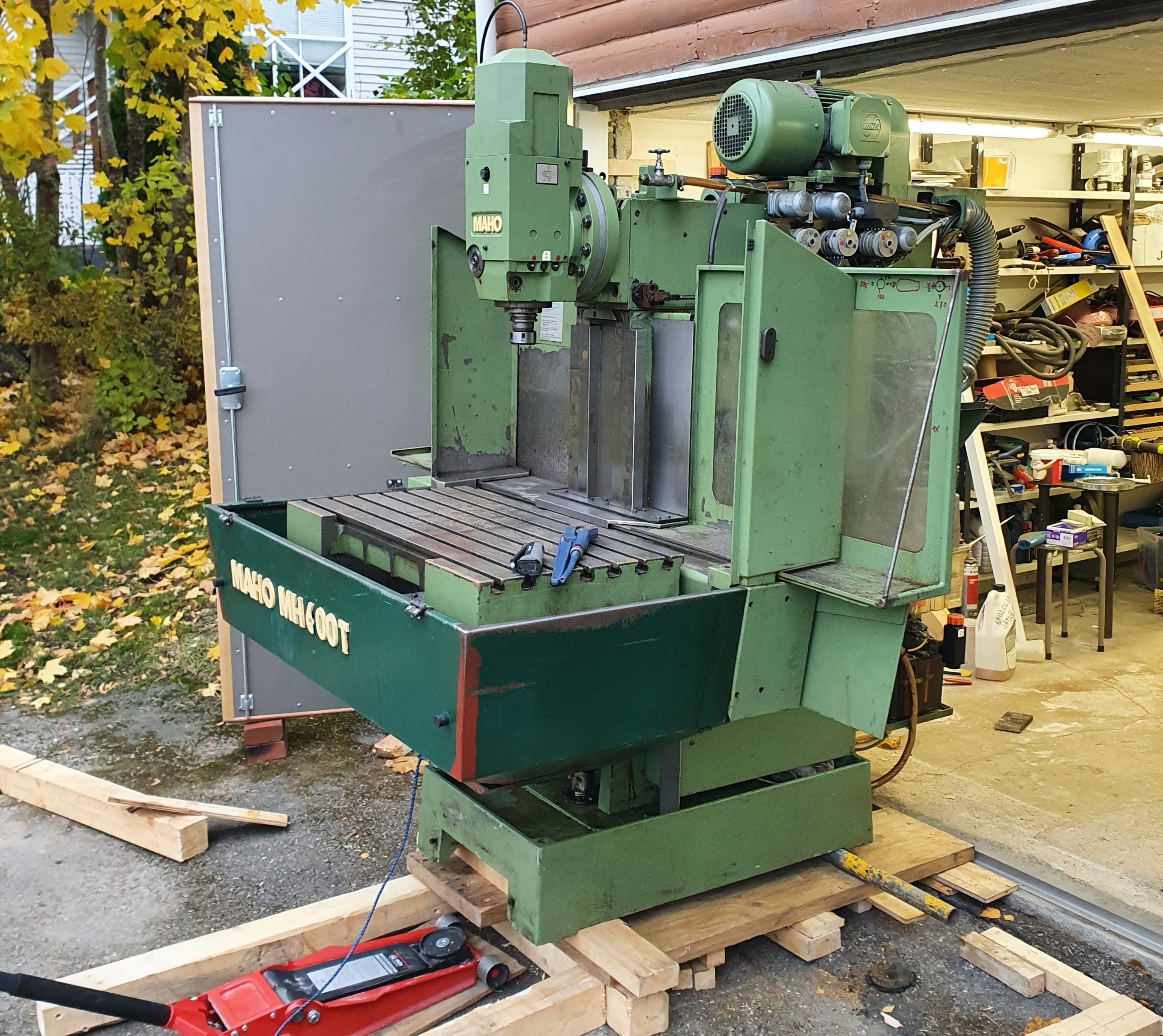
Some time ago, I bought a Maho MH600T milling machine that had been stripped of almost all the electronics. The previous owner had planned to retrofit it with UCCNC, because at least the machine parameters had been lost from the original control system. Unfortunately, all the servos and drives had already been scrapped along with everything in the control cabinet. The previous owner had bought new 1 kW Leadshine servos and drives for the X and Z axis, and 2 kW for the Y axis (which on this machines is the vertical movement).
This is pretty much where I pick up. I briefly looked up UCCNC, but quickly realized that it would not be able to use the feedback from the Heidenhain linear scales (which fortunately hadn't been scrapped). And because I already was familiar with LinuxCNC from a previous conversion of a Optimum BF20 machine, that was the logical choice here as well. I made a thread on Practical Machinist also, but that will focus more on the mechanical aspects.
For the controls, I will use a Mesa 7I95T and a 7I84 daughter board. I started working on the control system design/drawings, and have attached a first rough and unfinished draft of those. While I didn't get a circuit diagram for the machine, I found something for a similar machine online. I tried to retain at least a bit of the component labels.
At the moment, it's fairly clear how to proceed with the control system design. However, I might insert a question already at this point. My idea is to have one emergency stop circuit and one machine power (latching) circuit. Because the emergency stop will simply cut the power, I thought it might be nice to have a possibility to do a more controlled/soft stop as well. Maybe somebody can comment if this is the right way:
Emergency-stop:
iocontrol.0.user-enable-out: I put this as a condition in the hardware emergency stop circuit
iocontrol.0.emc-enable-in: This will be written based on a digital input "monitoring" the emergency stop circuit
Machine power:
I had planned to use the halui.machine.on and halui.machine.off pins as one way to enable/disable the machine (in addition to physical buttons). But now when I look at it again, that does not seem to be the correct way to do it at all (mainly because I don't think it will work like that). What I want is that when the power toggle button in axis UI is pressed, it controls a digital output which turns on the machine enabled holding circuit. That state of that holding circuit is read with a digital input which would give also give the depressed state of the button in axis. And if enabled, the pressing the axis power toggle button would trip the machine enabled circuit through a digital output. I actually don't plan on using the axis UI, but perhaps this is standardized across the UI:s? Otherwise, I guess a can make my own button for the behavior I want.
It would be easier to start building the circuit bit by bit. But I don't feel like doing that. I would prefer to make the initial design good enough that I can build the control cabinet and make only smaller modifications as needed along the way.
And still another question: What physical indications / push buttons would you recommend for the control panel? I know this is almost like asking how long a rope is, but nevertheless. I plan to get a decent pendant to use for "manual operations" and overrides, and didn't plan to add too much to the main control panel.
Attachments:
Please Log in or Create an account to join the conversation.
- tommylight
-

- Away
- Moderator
-

- Posts: 21764
- Thank you received: 7438
")
The Y moving up/down is not how it should be, Z is for that and probably the 2KW motor will be for that.
Answering your question with a question, did you check the build logs for Maho's on this forum, RotarySMP has a very detailed log here with videos:
forum.linuxcnc.org/12-milling/33035-retr...g-a-1986-maho-mh400e
Please Log in or Create an account to join the conversation.
- pippin88
- Offline
- Elite Member
-

- Posts: 263
- Thank you received: 51
Unless I am missing something, it is a 3 axis vertical mill? Life will be easier if you follow the standard naming convention. The naming is based on the tool movement.
Z is tool movement inline with the spindle (i.e. up and down on a vertical). X is tool side to side / left - right, with the operator standing facing the machine in the usual position for use. Y is tool moving away from or towards the operator, standing facing the machine in the usual position for use.
In your case, Z involves the table moving up and down on the column.
Y involves the ram moving in and out at the top of column.
I presume the table moves side to side on the column (hidden by machine guards / drip tray) - X axis.
On a horizontal, the spindle is horizontal and Z again is the tool moving inline with the spindle.
A rotary is rotation around the X axis
B rotary is rotation around the Y axis
C rotary is rotation around the Z axis
Please Log in or Create an account to join the conversation.
- Finngineering
- Offline
- Premium Member
-
- Posts: 110
- Thank you received: 49
The Maho MH600T has a horizontal spindle as well as a vertical. The vertical head visible on the photo swings to the side and exposes the horizontal spindle. I guess Maho considered the horizontal spindle as the main one and based the coordinate system off of that (I would image it's slightly more rigid). I will retain this axis convention at least for the mechanical and control cabinet. It's easy enough to switch it around in software (LinuxCNC) in case I prefer the more common coordinate system with the Z axis being vertical. For CAM programs, it would be all the same for me, but maybe for jogging/manual work it will be easier with the Z being vertical. I recall one physics teacher saying that "you can choose any coordinate system you want, as long as it's right handed".
Yes, the table moves side to side together with the drip tray.
I have been working quite much on the control panel design since the first post. One issue has been to figure out the physical layout of the components. I want to fit everything in the original cabinet on one back-plate, and there are enough components that this is not straightforward. But I think I start to have it figured out now. I still need to order some parts before I can make it somewhat complete, though.
For the Heidenhain linear scales, I plan to use my own "EXE" converters, and have been working a bit on that today. I think I could make a separate thread about that in the future, when I have verified that all works as expected. Hopefully others could benefit from this as well. But I did put what I have on Github already:
github.com/finngineering/sincos_interpolator
I had some boards made previously with revision 1.0 boards (now 1.1) and they appeared to work as expected. But I need to have the machine move under power before I can fully test them.
Please Log in or Create an account to join the conversation.
- Finngineering
- Offline
- Premium Member
-
- Posts: 110
- Thank you received: 49
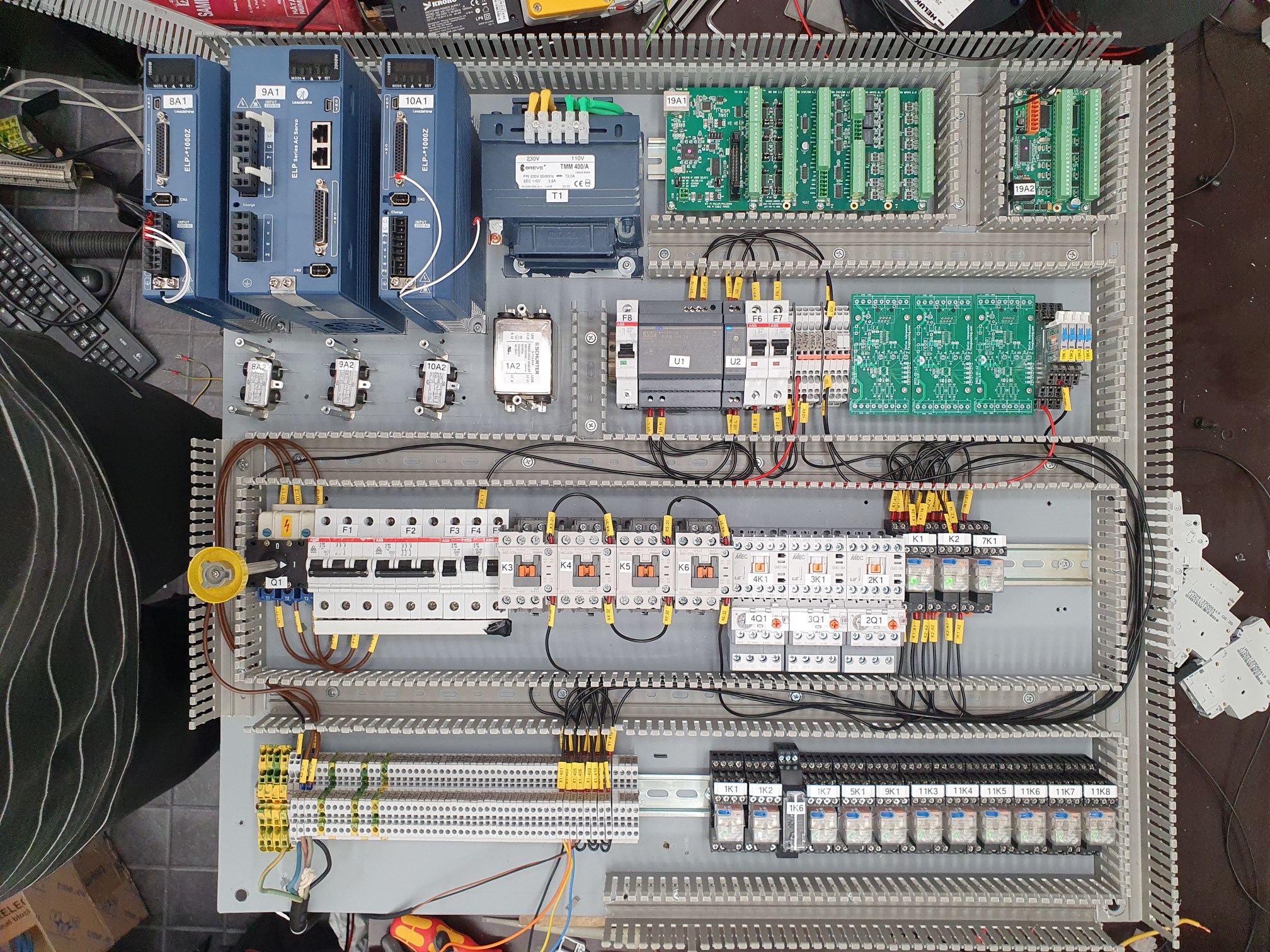
I have continued working on the control cabinet schematics and layouts, and now start to be suffiently satisfied that I will actually start wiring it up. This is how the layout looks like right now:
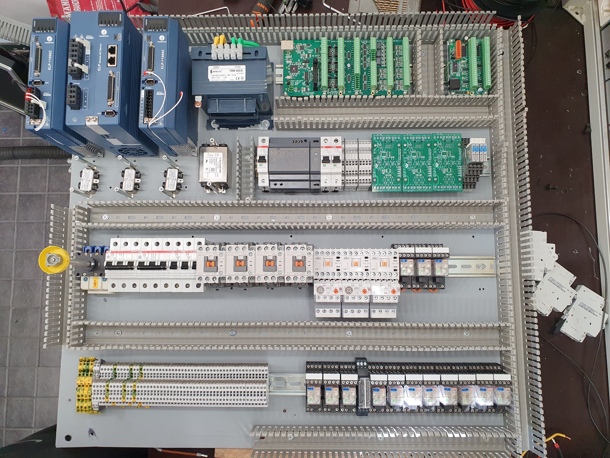
There are still missing a few terminal blocks, but other than that I hope it's fairly complete. A new draft of the circuit diagram is attached as well.
The servo drivers have sinking outputs, and becuase of that I was not really planning to use much of that information. But more or less by accident, I realized that the 7I95T inputs can "read" sinking outputs. And I have way more inputs available than I need, so now I can connect that to LinuxCNC as well at almost no cost. The Mesa cards provies such a nice solution.
I noticed that my own "EXE" interpolator had an issue with the power supply polarity to the differential line driver IC. In my opinion the MC3487DX symbols is strangely drawn in Kicad. I have now updated the design to version 1.3 and ordered new PCB:s.
Please Log in or Create an account to join the conversation.
- Finngineering
- Offline
- Premium Member
-
- Posts: 110
- Thank you received: 49
For some initial testing, I moved the electrical back-plate closer to the machine and hooked it up to the x-axis.
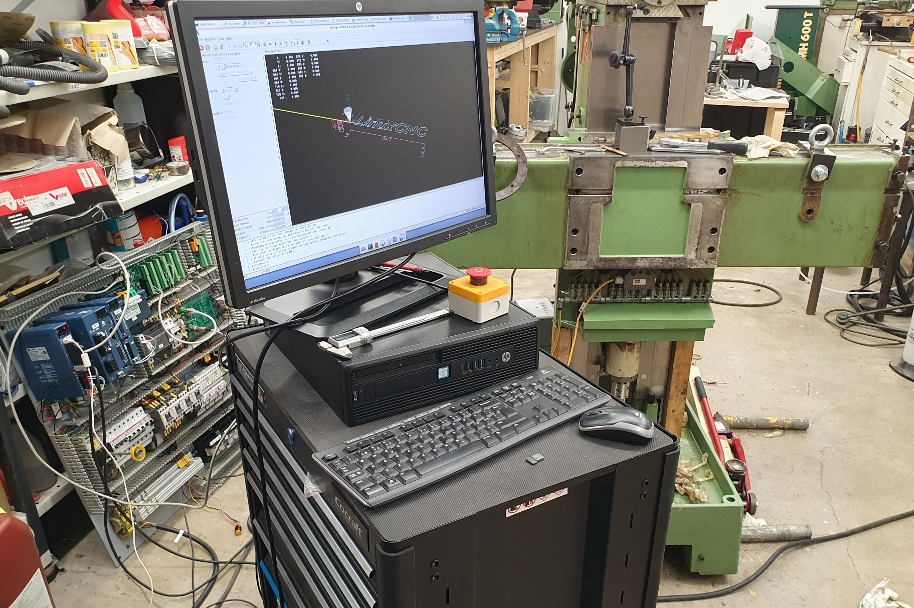
With some initial tuning, I got down to a maximum following error of around 15 µm on a linear move with 1000 mm/min feed and 500 mm/s² acceleration. To me, this feels like a decent results. But maybe some of the more experienced people here could give their opinions?
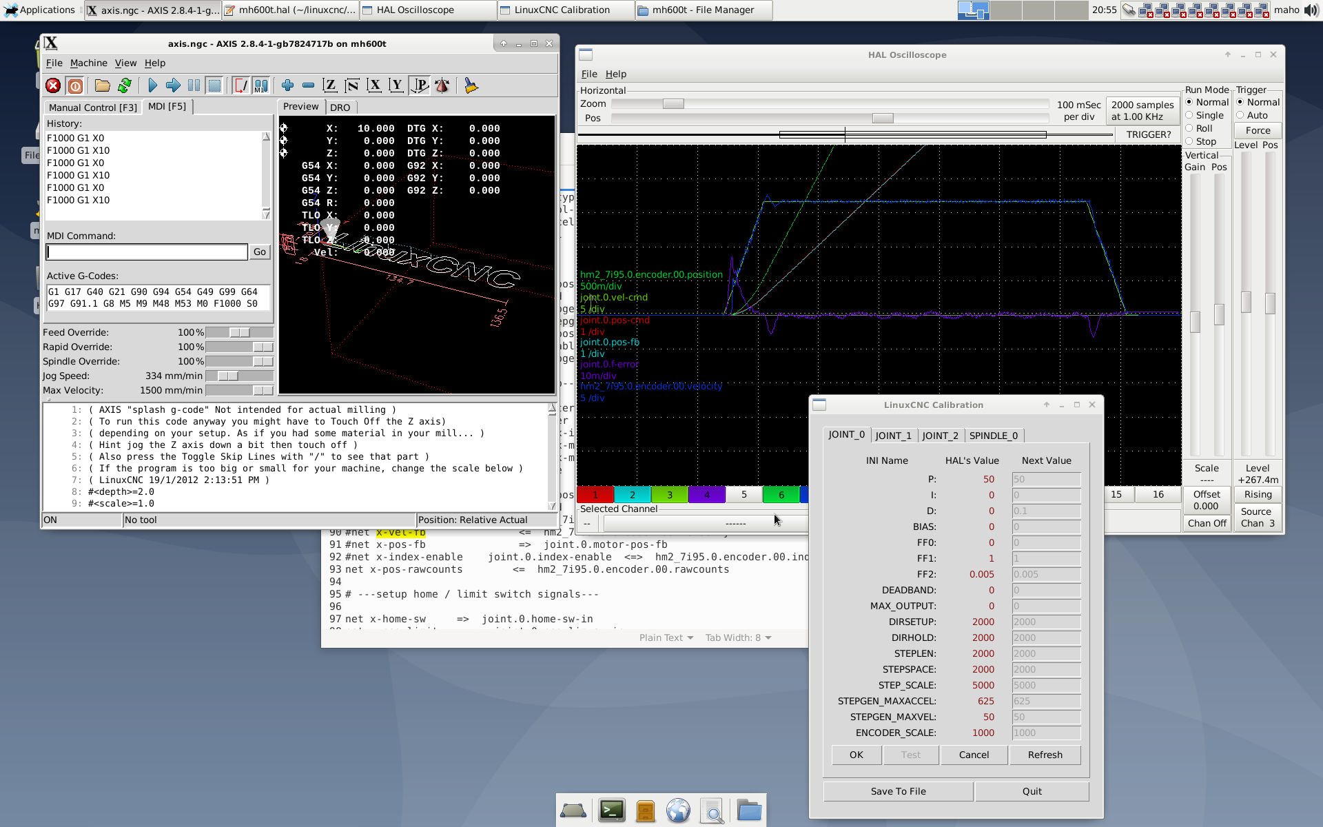
For the electrical end stops, I had the idea that the servos will likely stop faster under power than if removing power. I had even planned to have a short delay for cutting their power after the emergency stop circuit tips. And now when I have one axis moving under power, I could test that. So I set up one electrical end stop closer to the middle of travel. Moving at 3000 mm/min into this stop gave the following results:
Hardware stop only: 16 mm overtravel
Hardware stop + triggered software stop: 4 mm overtravel
The machine should have ~7 mm between the electrical and physical end stops. In conclusion, there is no need or benefit to delaying the power off of the servo drives. On the other hand, the software e-stop needs to be triggered to have the servo stop fast enough.
I got the new PCB:s for my SinCos interpolator, and so far, these have been working as intended. But I have not really put them under any real test to see if the miss any steps under high speeds.
Attachments:
Please Log in or Create an account to join the conversation.
- ihavenofish
- Offline
- Platinum Member
-

- Posts: 1028
- Thank you received: 286
tommylight post=278432 userid=17274Those are nice machines!
The Y moving up/down is not how it should be, Z is for that and probably the 2KW motor will be for that.
Answering your question with a question, did you check the build logs for Maho's on this forum, RotarySMP has a very detailed log here with videos:
forum.linuxcnc.org/12-milling/33035-retr...g-a-1986-maho-mh400e
Maho (and deckel) always have the ram as Z. These are technically horizontal machines, traditionally operated from the right rear side of the table. If you imagine taking a regular mill and flipping it on it back, this is what a maho is.
Please Log in or Create an account to join the conversation.
- besriworld
- Offline
- Elite Member
-
- Posts: 317
- Thank you received: 85
I have a question . Where can I buy this integrated circuit " iC-NV chip" .
Looks like furnell doesn't know about this chip
What is the price ?
I have schneeberger linear guides with a built-in linear scale sin/cos 1vpp
Please Log in or Create an account to join the conversation.
- Finngineering
- Offline
- Premium Member
-
- Posts: 110
- Thank you received: 49
www.distrelec.biz/en/sine-converter-ic-b...v-tssop20/p/17350855
They are not particularly cheap. I probably ended up spending slightly less than sourcing three EXE:s from ebay. But cost was not really a deciding factor for me.
Please Log in or Create an account to join the conversation.
- vre
- Offline
- Platinum Member
-
- Posts: 610
- Thank you received: 17
Are these converting uApp sin/cos signals to quadrature? What interpolation they have?
Please Log in or Create an account to join the conversation.